


Pulse-Width Modulation
Pulse-Width Modulation (PWM) is a common technique for controlling the speed of a DC motor with a digital controller. It is so common that PWM controllers are built into some microprocessor chips used as integrated controllers. A Digital Command Control (DCC) decoder uses PWM to control the speed of the motor in a model railroad locomotive or other motorized vehicle. PWM is just one aspect of controlling a motor, and others are discussed on the parent DCC Motor Control page. This page gets into the details of just how PWM is used, and what options you might have for adjusting it (and why you’d want to).
Reminder: in a DC motor, the basic principle of operation is that applied voltage creates an electric current through the motor’s windings, these are wrapped around a ferrous core called the armature that connects to the shaft of the motor so the current creates a magnetic field in the core, and the armature is mounted in a frame containing a fixed permanent magnet, so the interaction of the two magnetic fields creates a torque (force) on the armature, causing it to turn. The torque is proportional to the current, and the current is limited by the voltage (and a bunch of other factors we’ll get into below). Thus voltage essentially determines the unloaded speed of a motor, and how much torque is available from the shaft of the motor. Turn up the voltage, and the motor spins faster if the load is constant. Add more load, and the motor slows down if voltage remains constant.
Decoder Design
In a modern decoder, most of the functions are handled in a microprocessor. Because microprocessors continue to get smaller and faster, newer designs can do more processing in the same space, leading to features like Back Electro-Motive Force feedback control (commonly called BEMF) and high-frequency PWM (marketed as “supersonic” output, although it really isn’t). This also results in more miniaturized decoders with the same capability as larger ones of the previous generation. The microprocessor will set the motor controller to output a specific average voltage (called a “duty cycle”) when it receives a throttle change from the user, and then go off and do other things. The motor controller is a tiny bit of hardware that will output PWM with the requested duty cycle until told to change it.
The motor controller itself is typically a very simple device, often part of the microprocessor “chip” on the decoder, that has a couple of “registers” allowing its operation to be controlled by the software running on the decoder’s microprocessor. The user doesn’t program the speed in the controller directly, but rather can set variables (CV’s) that the software uses to decide how to program the controller. And the software may alter the controller’s settings hundreds or even thousands of times a second. But if not, the controller will keep on doing the last thing it was told to do: run the motor at voltage “X” in one direction or the other.
Why PWM Is Used
PWM is desirable as a method to control a DC motor digitally because it is efficient (no power is wasted as heat as in a resistive control) and simple to implement in a digital circuit, requiring only fast-switching power transistors and a counter to time their operation. These translate directly to lower costs and smaller and cooler-running, and thus more reliable, circuits. They also use less power, which is beneficial with running a lot of trains off one supply.
What PWM Means
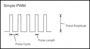
In PWM, a “pulse” of power is provided where the voltage is changed from zero volts to the maximum available (the Pulse Amplitude). The pulse lasts for a time (Pulse Length) and then is off. The controller repeats this cycle on a regular interval (the Pulse Cycle). The reciprocal of the length of this cycle is the frequency of the pulses, which can range anywhere from a few tens of pulses per second to more than 20,000. The amplitude of the pulse will always be the same, and in a DCC decoder’s output it is the rectified track voltage, so it will typically be about 1 volt less than the peak voltage on the track (around 11 - 15 volts for a typical N or HO decoder pulse).
WIth simple PWM, the pulse cycle remains constant, as does the amplitude, and only the pulse length is varied to control the average power in the motor. However, because the PWM controller can be reprogrammed on the fly by the microprocessor, it is possible that the pulse cycle length could also change dynamically (this would no longer be PWM but rather a mix of PWM and PPM, or Pulse-Period Modulation). I haven’t (yet) seen a decoder do that.
Decoders will, however, turn PWM off entirely for a time so that they can measure the voltage generated as Back-EMF by the spinning armature, which is how they estimate the speed of the motor and adjust it (the whole process is typically called “Back-EMF” or “BEMF”). The exact length of the gap required depends on electrical characteristics of the motor, and thus will vary a bit between individual models with different motors.
Controlling Speed With PWM
As mentioned above, in a PWM motor controller, power to the motor is regulated by varying the duration of PWM pulses. These can be as simple as turning the power on for X% of some period and then off, and simply repeating the cycle to create a chain of identical “pulses” of power, or can be much more complex and arrange these pulses into groups of varying duration. But in the end they’re all doing the same thing: turning full power on for some fraction of the time, and off for the rest. By doing this, the controller is varying the average voltage supplied to the motor. And in a DC motor, speed is proportional to voltage. Thus it is varying the speed.
But a DCC decoder has no way to know what the track voltage is, or how fast (in RPM) its motor is turning. All it knows is that at throttle speed step N it should provide X% of power to the motor. What “X” is, can be defined in a number of ways (such as a speed table) and modified in others (such as applying BEMF-based adjustments) before the value is given to the motor control circuit itself. What the PWM controller then does is issue pulses of the necessary length at the requested frequency.
And the requested length of the pulses will be based on some integer subdivision of the interval that corresponds to the requested frequency. A common subdivision (for reasons we’ll get to later) is 256. So if the interval were 1 millisecond, then each pulse would be an integer multiple of 1/256 milliseconds, or roughly 3.9 microseconds. A throttle setting of 10 (out of 256) would equate to 39 microseconds per pulse, and full throttle would equate to 3.9x256 microseconds, or 1 millisecond (at full throttle each pulse runs into the next one and power is on continuously, at least until we complicate things with BEMF). These integer multiples of some base pulse length are called “speed levels” and are an attribute of the hardware of the decoder (e.g., in this example “level 1” is a pulse of 3.9 microseconds, “level 2” is 7.8 microseconds, and so on up to “level 255” which is essentially continuous power).
Although the motor controller deals with the motor in terms of pulse duration and the delay until it repeats the cycle, the decoder deals entirely with a percentage of track voltage, typically expressed as a number from 0 to 255 (where 255 = 100%). This exactly fits in an 8-bit Configuration Variable (CV). So the end-user programming the CVs in a decoder to run a train is really working in percentages of track voltage expressed as a 0-255 number.
For example, in the photo below, a TCS M1 decoder’s motor output (orange and gray wires) is measured with the throttle set at step 64 (out of 126), or roughly half power. Each pulse lasts about 25 microseconds (the Pulse Length) at maximum amplitude (15.03V DC). The power is being pulsed roughly every 62.5 microseconds (the Pulse Cycle time), or at a frequency of around 16,000 Hz. Looked at another way, with a frequency of 16 kHz, the the Pulse Interval is 62.5 microseconds, and if this is subdivided into 256 speed levels, then each pulse is an integer multiple of 62.5 / 256 = 0.244 microseconds, so half power is about 128 x 0.244 = 31.2 microseconds (while I said 25 microseconds above, the oscilloscope I used here isn’t accurate enough to tell 25 from 31).
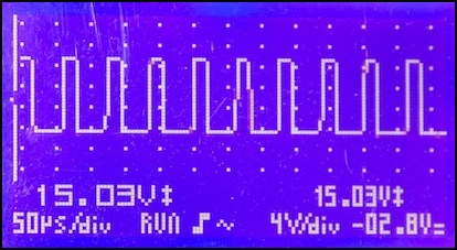
M1 Step 64: 16 kHz PWM (at 50 µseconds/division), 15.03 volts peak-to-peak
The person who set up (“programmed”) the decoder can define the voltage percentages set by the decoder at various speed steps, using either a simple min/max basic speed table for a more detailed 28-step speed table. And in doing that, they can make assumptions about the track voltage, and work with knowledge of the train’s motor and geartrain design. Thus the decoder programmer could know that the train will, for example, go 183 scale kph at full speed on a 14V DCC layout, and scale the maximum speed step to be 2/3 of track power to provide for 120 scale kph (meaning set the top speed CV to 2/3 of 255, or 170. Unfortunately if someone then takes the train to a 12V DCC layout, it’s going to run about 14% slower (and things get more complex with BEMF).
We’ll get into programming and the choices that can be made later on. But the decoder isn’t aware of any of that, it’s just doing what it was told to do, and providing 170/255 of whatever voltage it’s supplied with when it receives a “go speed step 126” command.
PWM Frequency and Torque
As the voltage varies from zero to peak and back in a square wave, the current passing through the armature windings actually increases and decreases in a sawtooth pattern. This is because the armature and windings form an inductor, and in an inductor current doesn’t immediately rise to the level allowed by the resistance. Instead it climbs asymptotically towards it. For a typical small DC motor, it will rise to 99% of the maximum in as little as half a millisecond, and at most tens of milliseconds, although just how rapidly depends on the specific motor design.
Note: for the mathematically-inclined, current rise occurs based on the time constant, τ, which is computed from the inductance (L, in Henrys) and resistance (R, in Ohms) as τ = L/R. At half throttle when the PWM looks like a square wave, after time τ from the start of voltage, current will be at 63% (1/e) of the nominal value, meaning 63% of 50% or 31.5%. At time 3τ it will be at 95% (of half-throttle) and at 4.6τ at 99% (see motor tutorial in references). For a typical N-scale motor, τ is measured in hundreds of microseconds or more, so near-full current will be reached in no more than tens of milliseconds if power is applied continuously for that long.
And current is important, because torque, the force used by the motor to overcome friction and other sources of drag, is based on the current, not the voltage. Voltage makes the motor spin, but current makes it propel the train.
What this means is that for a PWM controller with a frequency of even 1 kHz and a 256-level motor controller, the current may not ever reach 99% of that possible, because the longest pulse (other than 100%) lasts barely a millisecond. And the higher the frequency gets, the further from optimal the current will be. This is the fundamental reason “supersonic” PWM has less torque than even normal (kHz) PWM, and normal PWM has less torque than real DC (which will reach 100% of current, or fairly close to it, after even a fraction of a second).
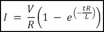
There’s a formula for the current in an inductor as a function of elapsed time:
where:
I = current (Amps)
V = voltage (volts)
R = resistance (of motor windings) (ohms)
L = Inductance (Henrys)
t = time (seconds) since application or removal of voltage
The inductance of a motor is the hardest part to know. Multimeters that measure inductance are uncommon, and typically only measure it at one frequency (unless they’re very expensive meters), and motors are “non-linear” inductors because of their use of a soft-iron core, meaning that their inductance changes with frequency. Note that the stall current is the maximum current, so you can calculate the resistance if you know the voltage and stall current (from R=V/I) or the stall current if you know the resistance (I=V/R). But at best you can only approximately know the inductance unless you have much better equipment than I can afford.
Note: I had problems measuring resistance of the motors, and ended up calculating it from the observed stall current (R=V/I is valid if you let the current run long enough to stabilize). I did measure inductance (L) with a meter that’s probably using a 1kHz frequency, so extrapolating that to 16 kHz is likely to introduce some error, but that’s the best I can get with the instruments I have.
The following diagram illustrates the behavior of current in a typical N-scale motor. This was one of my Kato E231 motors, a 3-pole skewed-winding motors, but I actually saw nearly identical numbers from a five-pole motor (see my Typical Motors page for specific numbers for each). The current shown here is, of course, theoretical, derived from motor R/L constants rather than measured. It’s also not showing BEMF, so this is the maximum current that can be produced to pull a load; actual current in normal operation would be lower.
The graph shows current with the motor driven at 16 kHz. Current (blue line) rises exponentially once voltage (green line) is applied, and declines exponentially when it is removed.
Note that the current isn’t climbing anywhere near peak current, despite the voltage during the pulse being at peak. That’s because the peak is too short even starting from 250 mA for it to climb very far in the time the pulse is on. What really matters though is average current, not the peak.
Here the current is oscillating around 300 mA (about 60% of the 500 mA stall current). The oscillations amount to 20% of the range, so this is relatively inefficient, but not terribly so. This is a consequence of this particular motor having a time constant equating to a 12 kHz frequency, so we’re just a little above that, allowing for a significant drop.
Note: I’m still not sure these diagrams are right, although they’re closer to correct than the old ones. More work is needed on this.
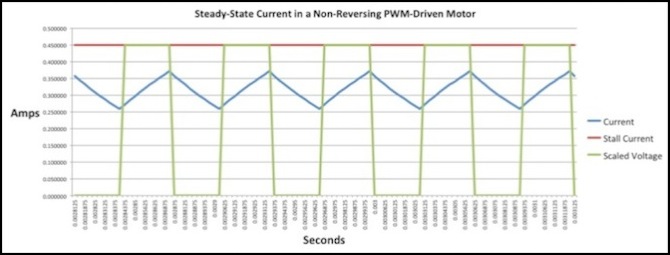
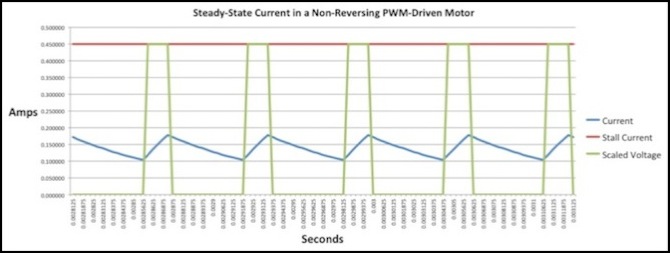
PWM Current (blue curves) and driving voltage (green square waves, scaled to show 100% at 0.060) for 50% throttle, 16 kHz PWM
At 25% throttle, the current is much lower, averaging around 150 mA. The amount of oscillation, at about 75 mA, is lower than at 50% in absolute terms although larger relative to the actual current. This is about as expected: the exponential decay keeps the motor from loosing too much field strength, even over a relatively large gap.
PWM Current for 25% throttle, 16 kHz PWM
In contrast, here is the same motor at 25% throttle with 1 kHz PWM. Now the pulse is long enough that the current can climb nearly to 100% strength, but then the gap is correspondingly longer, so it can fall all the way to zero and remain there. The average probably works out the same, but the large swings correspond to more energy lost as heat in the armature.
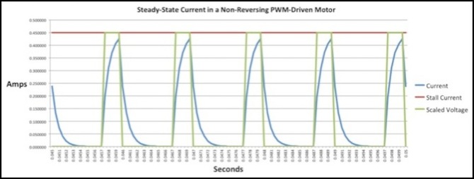
PWM Current for 25% throttle, 1 kHz PWM
Let’s look at one more example, how the motor would react at 32 kHz. The oscillations are much smaller than at 16 kHz, although average current is roughly the same.
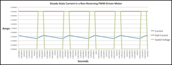
PWM Current for 25% throttle, 32 kHz PWM
PWM Frequency and Noise
When the pulse goes through the windings, the magnetic field increases, causing an increase in speed. It also causes an increase in the tugging force between the armature and the frame of the motor due to the increased magnetic field. When the pulse ends, the tug relaxes. The effect is to cause the motor to vibrate slightly, at the same frequency as the pulses. That means that the vibrations created in the motor by turning the power on and off with a 16kHz PWM signal will have a sound frequency of 16 kHz also. That’s not quite “supersonic”, but it’s going to be hard to hear for the average older modeler.
There’s another kind of noise to be concerned with, Electromagnetic Interference, or EMI. As the decoder’s PWM frequency becomes higher there is an increased quantity of EMI produced by the switching transistors in the motor controller, as well as by the brushes in the motor. This can be filtered in a variety of ways by the designer of the decoder, but doing that adds to the complexity (and cost). And failing to do it could run afoul of regulations on acceptable radio interference.
So while higher frequencies are good for acoustic noise, they have a cost for the decoder manufacturer (and thus for the person paying for the decoder).
Most modern DCC decoders use high-frequency PWM to control the motor, as will be described in the technical section below there are limits to how high this can be, and some advantages to lower frequencies, but most decoders will use a frequency around 16 kHz by default.
PWM and the Motor Time Constant
A motor is an inductor, and thus is can be characterized by a “time constant”, which is simply the inductance divided by the resistance (L/R) and gives a number in seconds. Taking my typical N-scale motor, this gives me 2.3 mH / 26.7 ohms, or a time constant of 86 microseconds, which equates to a frequency of 11.6 kHz. The other N-scale motors I measured had frequencies between 8 kHz and 12 kHz (HO motors were slightly lower, but I didn’t measure many of those). A good rule of thumb is that to avoid excessive heating in a motor from PWM, the frequency must be “significantly above” the time constant, as illustrated in the graphs of motor current above. This is another argument in favor of using supersonic PWM.
The issue here is that it takes a time related to the time constant for current in the motor to rise (and decay). That time is based on the creation (and relaxation) of the magnetic field in the motor, and uses up energy. When the field decays, the energy spent creating it goes somewhere, and that’s into the motor’s armature as heat. In technical terms, this is called “hysteresis loss” by motor designers. A short pulse with a long gap implies the maximum loss as heat, where a long pulse with a short gap or a very short pulse repeated before the field can decay will minimize such loss.
There’s a second issues as well: whenever a magnetic field is changed, electrical currents are induced in conductors. Because the armature is a conductor currents, called “eddy currents” are induced within it, wasting some energy as heat each time. More pulses per rotation means more changes, and more lost energy, as well as more heat, which could damage the windings at higher loads on the motor, since current through the windings would also be producing heat. The only way to avoid that is to limit the current, so at higher PWM frequencies the motor must not be run at full voltage with a full load. Exactly what amount is safe is not well defined, but the basic point is that the higher the PWM frequency, the more heat is produced from eddy currents and the less margin there is for heat produced by current in the windings, and hence a lower limit on motor pulling power.
Motors are designed to somewhat limit eddy current loss though the use of layers of stamped metal for the armature, rather than a solid casting. While use of layered armatures reduces manufacturing costs, the smaller portions of metal also reduce the amount of energy lost in eddy currents by keeping the individual looped paths of that current small.
Thus the ideal frequency depends on the duty cycle of the PWM, and specifically on the length of the interval between pulses for the lowest speed (shortest pulse) we want to use, in order to reduce hysteresis loss. And this places a minimum bound on the frequency. But the maximum frequency is effectively limited by the loss in allowable current (i.e., the loss in effective torque) as more heat is produced by eddy currents.
So the ideal is to be enough above the minimum frequency set by the time constant to avoid hysteresis loss at low speeds, while not being so high as to create undue loss due to eddy currents. While we can calculate the former fairly easily, it is harder to determine the latter. But this is probably why “supersonic” decoders are just barely above the limits set by the time constants of typical motors.
Let’s Get Technical
So that’s the high-level view (really, it was). Let’s lift the curtain and see what goes on behind the scenes.
Motor Speed Levels
Because the interface from the microprocessor to the motor controller is digital, a speed is expressed as a level from zero to some hardware-based limit. And that means that the motor controller’s output isn’t a continuous range of speed, but a number of discrete speeds, often called “levels”. A typical motor controller may use up to 10 bits (1024 levels), but many use as few as 8 bits (256 levels). Since DCC only has 126 steps, that’s twice as many as necessary. A decoder could just choose to use only half of them (128 levels), but when adjustments to the selected voltage are made (such as with BEMF) it can be useful to have finer-grained control on the voltage being supplied to the motor.
And that’s the reason 256 is typically used as the number of steps (as noted further up the page). It’s enough to add one extra level in between the required ones, without requiring more complex (and thus more expensive) motor controllers. Exactly why more steps are more costly is an interesting topic in its own right, and I’ll come to that later, but first let’s take a look at how the PWM frequency relates to the motor speed.
PWM Frequency and Motor Speed
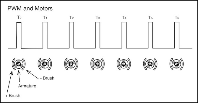
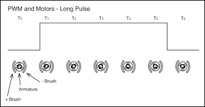
We’ll start with an example of how PWM pulses feed power into the windings of a motor. This example uses a three-pole motor, but the behavior of a five-pole motor is essentially the same. In the diagrams below, the output of the motor controller (PWM pulses) is shown at the top of each diagram, with an arbitrary time scale, and below this is a diagram showing the armature of the motor with the commutators (gray patches) as they move past one of the brushes (semicircle to the left). For simplicity the other half of the circuit and the other brush are not shown.
The following discussion is not entirely correct - rewrite needed.
At time T0, the positive brush is contacting one winding (lower left), the negative brush is contacting another (lower right), and the third winding (top) is not being energized (the gap is exaggerated here). At time T1, the “top” winding has moved to the left to contact the brush and is now energized, but the original “lower left” winding is still energized as well. At time T2 the first winding has rotated to the bottom and is no longer energized, but the former “top” winding (now “upper left”) remains energized. In fact, the winding that was at the top at T0 will be making contact with the brush from T1 to T5, but will no longer be touching it at time T6. A complete rotation of the motor here would require twelve time intervals, during two of which the winding’s commutator is not contacting the brushes (from time T7 to T11 the winding that started out at the top at T0 is now energized with the opposite polarity).
An important thing to observe here is that with three brushes, during a given motor cycle each will encounter the positive brush once (three “contact events”) and at the same time as each “event” one or more windings will be in contact with the negative brush. If power is fed in pulses as in PWM rather than continuously (as in DC) then there needs to be a minimum of three pulses per motor shaft rotation to energize each winding. Why not six? Because the windings are arranged back-to-back, energizing one “positive” is also energizing one or more “negative” on the other side of the motor. Note that with five windings (a “5 pole” motor) you need five pulses per cycle, not three, to ensure every winding is energized to each polarity in each cycle.
And if the “dead zone” between commutator sections (designed to keep windings from energizing at the wrong part of the cycle) is long enough, more than three evenly-spaced pulses could be required to bridge the gap and still energize all three windings at least once.
In this example there are more than three pulses per cycle. But note that this doesn’t mean that the windings are continuously energized. Between the pulses at time T0 and T1 there is no power to the brushes, and thus during this period while the winding could be energized, it is not. This is because the pulses are relatively short (shown here at about a 17% duty cycle), reflecting a low throttle. To an extent that’s desired, as we don’t want full speed in the motor at low throttle. There are problems however. We’ll come back to this in other sections below.
But the important part here is that there’s a fundamental minimum PWM frequency based on the rotational speed of the motor. And if the PWM “Pulse Cycle” is a fixed length (and it is), then this frequency has to be based on the top speed the motor will go in practice. That’s not the manufacturer’s rated speed with no load, but it is the speed the motor will be turning at for an unloaded train on level track. I measured one of my Kato motors, and at a rough approximation top speed is 16,000 RPM under those circumstances. That’s 267 revolutions per second (or 3.75 milliseconds per revolution). To get three pulses in that time, the interval must be less than 1.25 milliseconds (meaning a PWM frequency of more than 800 Hz), and to get 5 (for a five-pole motor) it much be less than 0.75 milliseconds (meaning more than 1,333 Hz). Thus, efficient use of a motor argues for a minimum PWM frequency greater than one kHz for a typical N-scale Kato motor (and for other similar motors).
Now if you know you’ll never run your motors at full speed, you can adjust that. A freight engine is going to have a much lower top speed than a passenger train, and they typically use exactly the same motor (although they could use different gear ratios). So a motor that needs 1,333 Hz in a passenger train, but is run at no more than half that speed in a freight engine could get away with a decoder PWM frequency of 667 Hz.
Rather than lots of short pulses, what if you used a pulse longer than the time the winding remained in contact with the brush? That would seem to be more efficient, and in some ways it is.
Let’s look at a pulse for 17% throttle where the winding remains energized from when it first touches the brush at time T1 until it breaks contact at time T5, as shown below. You would then need a gap five times as long as the pulse, meaning about 2.5 rotations of the armature, for the same average current (not counting inductance effects). The benefit of this long pulse is that the magnetic field strength in the winding would be maximized during that one cycle, providing the most amount of torque possible for a given amount of voltage and duration (i.e., for a given duty cycle at a set track voltage).
The problem is that 2.5 rotations with no power is a long time; at 17% of top speed a typical train will probably have moved close to 40mm (1.5”). That’s long enough for friction to slow it significantly. If the motor is turning fast enough, the fact that it’s only being given a “kick” of power once every ~3 rotations doesn’t really matter. And this is at 17% throttle where there’s only a 1/6 ratio of on to off. What about speed step1, where there’s a 1/255 ratio? To keep the pulse on for a full rotation, it much be off for 255 of them. That’s obviously not going to work, so at best you won’t really get a full-duration pulse at all speeds, you’d have to pick a speed above which you wanted full-duration pulses, and still live with shorter pulses at low speeds.
There’s also an inefficiency here. If the pulse is just long enough for one winding, even assuming you could somehow synchronize it, this means that the other two windings would be energized for only part of two cycles (one positive, one negative). A longer pulse to ensure all three are energized (one full rotation) would then require a longer gap (several rotations at this power level, hundreds if you tried to do it at speed step 1). The takeaway is that this “long pulse” approach isn’t very good at providing continuous power, and while it might be a bit more efficient at providing average power without a significant amount of friction, it’s probably not going to work well in a real-world environment.
Switching and Clocking Limitations of “Supersonic” PWM
High-frequency PWM has limits. Because this is creating a high-frequency wave by turning the power on and off, the transistors that do that must operate at a fairly high speed. To create a 16 kHz wave, they must turn from off to on, and then back to off within that 62.5 microseconds, meaning that they’re switching once every 31.25 microseconds. That’s fast. Not incredibly fast by modern chip standards, but still fast. And to do that, a bit of hardware is counting clock pulses to time the length of the PWM pulse. That means the clock needs to be running fairly quickly. In fact, it takes a clock measured in megahertz to produce a kilohertz-level PWM signal with the 256 levels typical of BEMF-equipped decoders. Doubling the frequency requires doubling the clock speed, and that has a cost (more expensive components, more careful design, etc) that will be reflected in the cost of the decoder.
That “twice every 62.5 microseconds” is just for an output that is on exactly half the time (the “base frequency”). If you want it to be on shorter or longer, one part of the wave will have its “on” and “off” decisions made more closely together, requiring a higher switching speed (more expensive power transistors) and thus a faster clock speed (more expensive chip and circuit design). Ultimately there’s a cost to faster PWM.
There’s a formula for this (see below for more detail). What it works out to is that for a PWM signal to have 128 steps (the minimum in modern DCC) in a 16 kHz signal it needs a clock running at about 2.05 MHz. Many BEMF control designs create additional “virtual” speed steps in between the real ones, to allow finer control. This has a direct effect on the clock speed required. To create one virtual step between each real one (meaning to use 256 motor-speed steps and to make the on/off decisions twice as fast), raises the requirement to 4.1 MHz. Changing the base motor frequency also affects the needed clock speed: going to 32 kHz with 256 steps doubles the needed clock to 8.2 MHz. There’s a very real cost to this, although it comes down every couple of years as chips get faster and cheaper. And with BEMF in the picture, it may be preferable to spend that extra capability on more speed steps for it, rather than on reducing the noise further with a higher PWM base frequency. The decisions involved in design of a motor decoder are not necessarily straightforward.
There’s also an inefficiency in turning those power transistors on and off too rapidly. Power is lost each time a transistor switches, and the faster they switch the more power is lost. Pushing PWM too high can have a significant performance impact due to switching loss, although I don’t have specific numbers for how high “too high” would be. I expect this is negligible in comparison with the general inefficiency of the motor itself.
Motor Controller Clock Speed
As noted above, the clock used to drive the motor controller must be much faster than the frequency of the PWM, and this increases as the number of levels of control of the motor speed (steps) increases. A PWM motor controller doesn’t set a motor to any possible speed, but to one of a number of levels from 0% to 100% of the speed possible with the available power.
For example, the PIC16F88 chip used on Kato’s EM13 motor decoder can produce up to ten bits (1024 steps) of PWM. If the chip is driven by a 3.6 MHz oscillator (and I think it is in the EM13), to get 8 bits (256 steps) of resolution the PWM frequency must be limited to about 14 kHz (per a formula in the datasheet for the PIC, which may be generally applicable to other controllers), and to get 7 bits (which is really the lowest you’d want) it must be limited to just under 29kHz. With an 8 MHz clock, 32kHz PWM is still slightly below 8 bits of resolution. Thus “ultrasonic” decoders with higher frequencies either have fewer bits of resolution, or require higher clock rates (which make the circuit design and testing a bit more complex and likely add to the cost). Digitrax notes that their FX3 decoders use 255 motor speeds in normal use, although the BEMF function claims to use all 1024 on the DZ125 at least.
I suspect the reality is that all current DCC motor control systems are at frequencies that yield around 8 bits of effective resolution, and that’s “good enough” to support 128 speed steps plus one interpolated BEMF setting in between each step with current clock speeds. Initial work with a scope suggests that these decoders are using a frequency of around 16 kHz for the PWM, but in some cases the signal is more complex than a simple string of pulses, and other frequencies (both audible and supersonic) may be included in the mix.
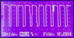
PWM Output from a decoder to a motor (Digitrax DZ125)
Motor Controller Steps and Clock Speed
I’m going to get a bit technical here about why PWM has “steps” and how those relate to decoder cost and PWM frequency. If you don’t care about knowing the “why”, simply understand that PWM needs at least 128 steps for DCC, and 256 is fairly common when BEMF is used, and there’s a cost reason why this tends to imply that “supersonic” decoders aren’t quite supersonic. And if that’s all you need, skip down to the next section heading.
In theory, PWM pulses could be sent with any duration, and continuously vary motor speed from zero to whatever maximum the available voltage made possible. In practice, PWM is produced by a digital motor controller chip that works by counting pulses from an oscillator and using an integer number of oscillator pulses to determine the length of each PWM pulse. A decoder doesn’t “known” what the available voltage is, it merely works with percentages of whatever is available. This means that there are discrete speeds the motor can turn at that are evenly “stepped” from 0 to “full” speed (whatever full means for that motor with a given supply voltage). For a typical model train motor and DCC controller, these are likely to be 256 steps, each about 40 RPM faster than the previous one (10,000 RPM motor divided by 256 steps). Since a typical train with typical voltage can run around 250 scale kph (I’m rounding a lot here), that means that each step represents about a scale 1 kph increase in the speed of the train. And since there’s no way to a human to tell 32 scale kph from 33 or even 34 scale kph, the result looks like a smooth and continuous increase in speed as the throttle is turned up.
This counter will have a size in bits, and 8 is common. If the oscillator is running at 1 MHz, and the counter has 8 bits, then the PWM pulse it generates can be anywhere from 1 microsecond to 256 microseconds long, but it can only be an integer multiple of 1 microsecond, it can’t be 1.5 microseconds long. The clock can also be scaled. If you wanted times up to 512 microseconds, every other clock pulse could be counted, and then the PWM pulses could be 2, 4, 6, etc. microseconds in duration, but never 1 or 3.
What this means is that the PWM pulse pattern has to repeat. Let’s assume that the clock is ticking once every 250 nanoseconds, meaning at 4 MHz. This means the shortest pulse is 250 nanoseconds long, and the longest is 250 x 256 = 64,000 nanoseconds, or 64 microseconds long. Assuming we want that longest pulse to mean 100% power, that means that the pattern repeats every 64 microseconds (making that the wavelength) since at full power the end of one pulse has to bump into the start of the next. And thus the frequency (1/wavelength) is 15,625 Hz. Which is very close to what DCC decoders called “supersonic” often use.
But that’s for 256 steps. If we used the same clock with 7 bits (128 steps), then the wavelength would be half as long (250 x 128) and the frequency twice as high (31,250 Hz, or really supersonic). If instead we wanted 1024 steps, the wavelength would be four times longer (250 x 1024) and the frequency a very audible 3,906 Hz.
And the clock is the same, make it run at half speed (500 nanosecond ticks) and the wavelength is doubled and the frequency halved for the same number of steps.
Put mathematically, the formula is: Base Frequency = Clock Frequency x 2^(Counter Bits).
I ran across a variation of this formula in a microchip datasheet that computed the usable bits of the counter (the steps) from the PWM frequency (the length of the cycle) and the speed of the oscillator (the ticking clock). If you have more bits in your counter, you won’t be able to use them, because you’ll get to the point where to stay at the desired frequency you have to repeat the pattern (so you might have 10 bits, but have to repeat after counting to 256, or 8 bits worth). That formula is:
Resolution = Log ( Fosc / Fpwm ) / Log(2)
where Resolution is the number of usable bits, Fosc is the frequency of the oscillator, and Fpwm is the frequency of the PWM.
When computing resolution from the PWM frequency and the clock frequency, you can end up with fractional bits. That’s okay, as it simply means that the ability to create the necessary number of steps is not quite exact. If you have 7.9 bits, you’ll miss an occasional step if you try to create 256 steps (8 bits), but you’ll mostly get it right, and that’s good enough for a motor controller. On the other hand, if you have 7.1 bits, trying to create 256 steps isn’t going to work very well, and you’ll end up doing about the same as if you’d tried for 128 steps (7 bits) in the first place.
These formulas are a useful guide to understanding approximately what is required to make a DCC motor controller work. DCC uses 127 steps (126 speed steps plus zero), meaning 7 bits of “levels” are required. Based on this relationship, for a PWM signal to have 128 steps in a 16 kHz signal it needs a clock running at about 2.05 MHz.
Many BEMF control designs create additional “virtual” steps in between the real ones, to allow finer control, so you’ll see decoders that talk about having “256 level resolution” . This has a direct effect on the required oscillator (which in turn affects the cost of the decoder in several ways: faster clocks cost more). To create one virtual step between each real one (meaning to use 256 motor-speed steps), raises the requirement to 4.1 MHz at 16kHz. Changing the base motor frequency also affects the needed CPU speed: going to 32 kHz with 256 steps doubles the needed processor to 8.2 MHz. There’s a very real cost to this, although it comes down every couple of years as chips get faster.
Magnetic Field Strength and Current
The torque of a motor comes from the strength of the magnetic field in that motor’s armature tugging and pushing against the permanent magnet of the frame. The strength of the magnetic field in an electromagnet depends on a number of things, but fundamentally it is proportional to the strength of the current flowing through the magnet’s windings. Thus, the motor’s torque is proportional to the current flowing.
The current in turn depends on the voltage and the resistance of the windings. But because an electromagnet is an inductor, the current does not go from zero to full instantaneously as the voltage is applied. Rather there is an exponential rise from zero to an asymptotic approach to the maximum (meaning that it gets most of the way there fairly quickly, but never quite gets all of the way there) as shown in the diagram in the PWM Frequency section above.
Electromagnets (and DC motors using an electromagnetic effect) are “non-linear” inductors. What this means is that there’s a relationship between the time it takes to raise the current up and the strength of the magnetic field in the armature that’s related to the frequency at which you’re trying to do it. I believe the next effect is to make it even less effective as the frequency is raised (above and beyond the basic problems this causes), but I haven’t found numbers to quantify this aspect yet.
The longer the motor voltage is on, the more the magnetic field can build up in the armature, and the more efficient the motor will be at converting electrical power to torque. But there is actually a limit to this in a typical brushed DC model train motor, since the armature winding is not energized throughout the full cycle of the shaft’s rotation.
Because the field in the winding (and the flow of current) reverses every half-cycle, this process has to start over twice per cycle in any case. With PWM, it has to start over with each pulse. So to maximize the current, it would be desirable to have all of the power being supplied in a half-cycle provided as one pulse.
If there’s only one pulse per cycle, or if the pulses are so far apart the field has collapsed, it will be harder to increase the current (take more time, or provide a lower strength for a given time of applied voltage). As it turns out, for typical motors the field will collapse far faster than the next pulse can arrive, until the duty cycle is well above 50%.
With short pulses, it’s better to put them close enough together to get multiple in one half-cycle of the motor rotation, so all of the windings are energized at least once. For a 12,000 RPM motor (200 Hz), a PWM frequency greater than 400 Hz is beneficial. On the other hand, this doesn’t rule out the advantage of a pulse that exceeds the half-cycle time when the winding is making contact, as shown in the PWM Example section up above. For the same motor, and assuming 256 speed steps, this means that the pulse must last longer than 1/256 of 1/6,000th of a second. Since that’s less than a microsecond, it’s not a hard requirement to meet at top speed, but at low speed it’s essentially impossible to have a pulse long enough, so you will always get multiple per half-cycle.
Optimizing PWM Frequency
You can’t really optimize the frequency, although there are some choices that can be made. Fundamentally the decoder has no way to know when the commutator is in the dead portion of its cycle and when it isn’t (I suppose current draw could be measured and a model built from that that was used to arrange PWM pulses). Assuming the dead zone is relatively short, and the pulse frequency high relative to the rotational frequency, this can probably be ignored anyway.
The other problem is that motor rotation speed is variable, and thus the frequency of the commutator reversals is variable. PWM by definition has a fixed frequency.
One thing you could potentially do is have the microprocessor reprogram the motor controller at each speed step, to “tune” the frequency to the speed of the motor. This would allow pulses to be longer at low speed steps and shorter at higher speeds. At least on paper, this should allow the “pulse” to be kept at a similar length (by shortening the cycle length in tune with the motor speed). When the motor is rotating a few turns per second at most, pulses would last 8-16 milliseconds at speed step 1, while at half throttle the motor is rotating about 100 times a second, and a half-period pulse would last around 5 milliseconds. Pulses in the millisecond range are guaranteed to always have full current for most of their duration (it probably takes about 0.4 milliseconds to get close to full current), and thus be very efficient.
I’m not aware of anyone who’s actually done that though.
References
DC Motors (PDF), Javier R. Movellan, MIT Tutorial
