


Elevated Station Structure
The Urban Station scene poses a special problem: it needs to be higher than the usual clearance provided by Kato’s viaduct piers in order to clear the “subway” tracks on the ground level. This meant I needed to come up with my own structure to support it. And one that would be on display since the area under the viaduct is meant to be a scene in its own right. That meant it needed to be fairly strong (six tracks worth of trains, platforms and track, plus the station building itself aren’t light) and yet look “prototypical”. I spent March and early April of 2010 creating the support structure.
The Prototype
Japanese elevated structures usually use concrete in square pillars as a support structure. But that’s not universal, and cylindrical columns are also used (and sometimes both). As the open part of the underside of the station was to eventually house a bus/taxi terminal in addition to the subway tracks, and thus be part of the “public” aspect of the station, I wanted the appearance to look as if an architect had tried for open space and clean lines.
Support Columns
At the same time, I wanted something structurally strong, which would support the viaduct platform elements. These are rectangular plates, connected to each other via Kato’s “S-joiner” links, which allow a fair amount of flex. I didn’t want to have to glue these segments together, so my support needed to somehow support all three plates (front to back) along their length (left to right). I ended up with three rows of support columns on 8-inch centers (about 100 scale feet or 30 meters, which looks about right for the size of the columns).
I’d been thinking about using 1/4” threaded rod and washers in some fashion, as these are easy to adjust for height and relatively simple to install. But giant screws wouldn’t look too realistic, so I needed to hide them somehow. And, while washers are good supports for a small area (and I used them at one point where clearances are a problem), they didn’t provide the broad area support I wanted, at least not without using far too many of them.
A trip to the local home supply store, and wandering around looking for inspiration, yielded the solutions to both problems. For hiding the threaded rod, 1/4” inside diameter PEX water tubing, and for support, a 12’ length of thin aluminum used to hold down carpet.
First, at the end where the subway tracks enter the station, there wasn’t sufficient clearance over the tracks to use the aluminum, so I used nuts and washers instead:
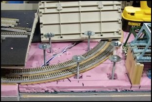
Subway entering the station, with threaded rod supports
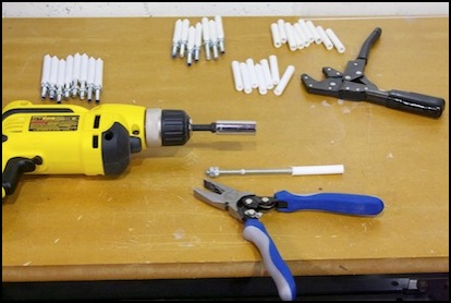
The threaded rod was fairly easy to work with. I bought it in 12” and 36” lengths, and cut it into 4” sections with a big set of bolt-cutters. Then I used a tap-and-die set to re-thread the end of the rod where the cutter had crushed the threads. To hold the rod while I re-threaded it I used a pair of locking pliers. Once one end was good, two nuts threaded on and locked against each other provided a place to clamp so I could fix the other end (and the damage done by the locking pliers).
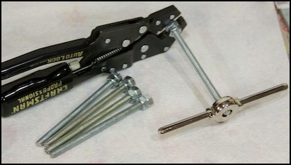
Re-threading a length of rod
Construction tip: two nuts tightened against each other won’t readily turn, so you can clamp to one of them to hold the rod still while working on the other end.
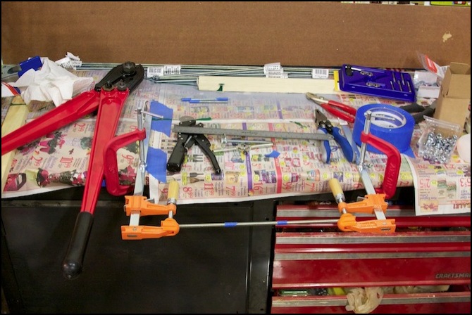
Threaded rod held between orange clamps, about to be cut, with other tools laid ready for use
I’d wanted to use PVC tubing around the rod, but they don’t make it small enough (or my local stores don’t carry it if they do). So instead I used PEX tubing, which is a flexible plastic tube used for water lines. The 1/4” tube has an inside diameter just a bit small, so the rod has to be screwed into it (an electric screwdriver with a socket wrench attachment is a lifesaver here). But once in place, it stays put, which makes it useful as part of the structure, not just as window-dressing.
Production line for support assembly
The PEX tubing comes with technical information stamped on the side in bold, dark, lettering. Following some tips for PVC tubing I found online, I sanded the PEX before cutting it, using 100-grit sandpaper to remove most of the lettering (some faint, red, letters remained, deeply embedded in the plastic). Then I used 150-grit sandpaper to smooth it off. This looked good before painting, but I ran into a problem with that later.
The tubing was cut into appropriate lengths with a saw, and assembled onto the rod segments. Everything was pre-fit to the table, then taken outside and painted with Krylon spray-paint for plastic (with quite a few coats needed for good coverage, perhaps a dozen at 30-second intervals; I used up a whole can).
After the paint dried, I realized something: PEX is a fibrous material, and there were little hairs sticking out, making my “concrete” columns look furry. Sanding this down with 220-grit fine sandpaper removed the hairs without removing the paint, although there’s still a bit more texture than I’d like. Although the color looks good for painted concrete, I may someday add some thicker paint (latex, perhaps) to eliminate the texture.
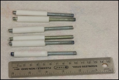
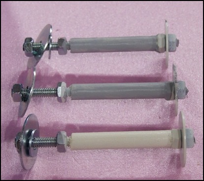
The picture below shows (L to R): an unpainted column, with red lettering faintly visible, a painted but unsanded column, and the sanded version.
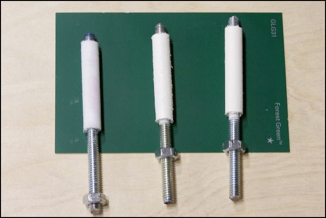
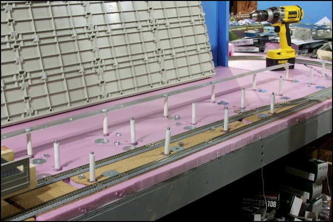
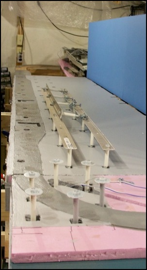
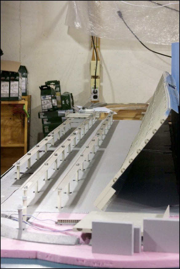
This was a lot of work: I used up a full weekend just making supports for one of the two tables. The photo below shows the first set of columns with the metal strip (in the rear), and the unpainted columns for the middle and front strips placed in their holes for alignment so I can drill the holes in their strips. When the platform (leaning up against the backdrop) is set in place, the nuts atop the aluminum strip with fit into the gaps between the ribs in the platform, and the ribs will rest directly on the aluminum. I did make one mistake: one rib rests directly atop a column, so I had to omit the nut and shorten the rod there.
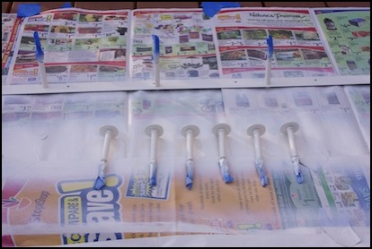
I’m thinking about perhaps doing something different with the posts. The white spray paint I used reveals the fibrous texture of the PEX tubing a bit too much, and is easily damaged by handling. I’m wondering if latex would bind better, and mask the texture. I tried painting a couple of the posts (see below) to see what it looked like. The color is too dark to my eye, although it may be a good color for unpainted concrete.
The aluminum is actually held up by the PEX tubing itself; there’s no nut between the two, which makes it much cleaner to look at. The rod is clamped in place by a nut/washer above and below the table.
One thing you might notice: the PEX doesn’t go all the way down to the pink foam. This was an oversight due to a design change. Originally there was a nut between the PEX and the aluminum strip, so a 50mm segment of PEX was all I needed. I eliminated the nut when I realized how snugly the PEX fit on the threaded rod, to make the columns look better. But that left the PEX too short. When I did the second half of the station I made them 60 mm, and then I re-did these but didn’t take another photo.
Material for one of the two tables: one 12’ length of carpet edging, one 5-foot length of PEX, one can of Krylon Dove White spray paint for plastic. Eight feet of threaded rod. Nearly a full 100-count box of 1/4” nuts, and about 50 washers. And at least ten hours of work, although some of that was learning what I wanted to do, so the second table went a bit faster (it was still four of five hours to get all the bits the way I wanted them).
After that, I turned my attention to painting the pink foam and the subway roadbed, using the usual gray latex primer for the foam, and gray artist’s acrylic paint for the roadbed. But before I applied the paint, I cut and test-fit the fascia panels, and some sheet acrylic (plexiglass) for the front. I also had to re-paint the original two fascia panels, as the clamps I’d used to attach them badly smudged the paint finish (latex may be dry to the touch in an hour or less, but it takes days or weeks to fully cure, and can be easily damaged until then).
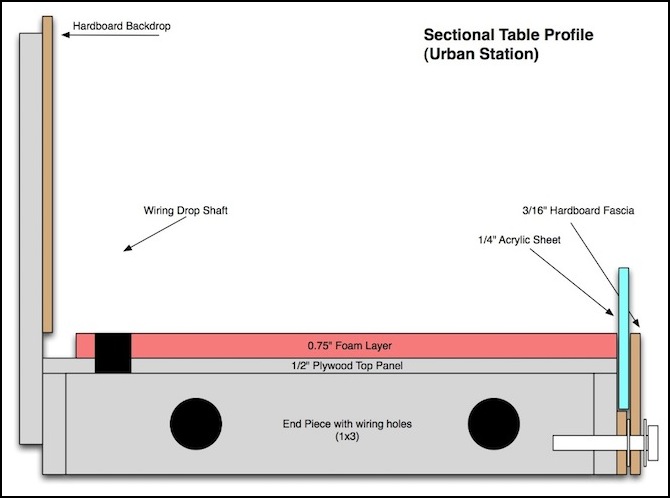
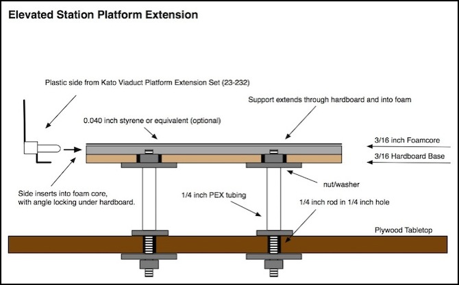
The reason for the acrylic is that I’m not putting the usual lip on the fascia, as I want to have the maximum possible visibility under the elevated station, so I need something to keep a derailed train from heading for the floor. The diagram below shows how spacers are used to mount the acrylic and fascia. The top of the acrylic comes up to about the bottom of the elevated section, and can be lifted out of the slot it’s in if I need to reach inside.
Below are a few more photos.
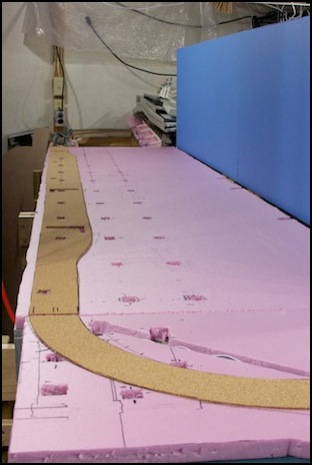
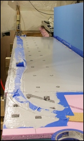
Before paint (L) and after initial coat of latex primer on the foam (R)
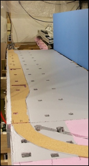
After drying (L) and after cork painted and with supports (R)
After more time to think, I decided that I really didn’t like the fact that the PEX didn’t go all the way down to the foam, even though it’s likely to be covered by pavement or other scenic elements, there may be places where the gap is visible. PEX is cheap, so I removed and discarded the set from the first half of the elevated station while making the second set, then I painted and sanded all of them at the same time. Much better.
And here are the assembled supports, with the viaduct (leaning on the backdrop to the right) waiting to be lowered into position. This isn’t the final form, but it’s getting close.
Platform Extensions
The elevated station was originally intended to be made entirely using Kato’s Viaduct Station (23-230) and Viaduct Platform Extension Set (23-232). The problem was that at the ends, the flat supports I was using to hold it up would come down into the space needed by the subway train, and raising it up another quarter inch wasn’t very desirable. Without those, the plastic tended to sag where it was unsupported.
The solution was to use a method described by cteno4 (Jeff) on the JNS Forum, a sandwich of hardboard for strength, foamcore to allow the plastic sides to snap in (and to make it the same thickness as Kato’s platform) and a topping of styrene (or linoleum) to waterproof and strengthen the surface. I’m using this, although at least for now I’m leaving off the top layer. Additionally the center section of the station remains plastic, since that part was okay.
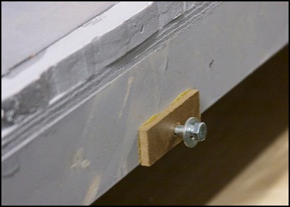
To hold it up, I’m using a variation on the posts that hold up the metal strips supporting the rest of the station: 1/4-inch PEX tubing screwed onto 1/4-inch threaded rod, with nuts and washers. To use these, holes slightly larger than the nuts are drilled into the hardboard where the posts sit before the foamcore is glued in place. Then the foamcore is glued down (with a very thin layer of carpenters glue squeegeed across the hardboard) and the underside of the hardboard painted (with my usual gray latex primer, at least for now).
The assembly is then placed onto the posts, and pushed down hard enough to seat the top of the nut and rod into the foamcore slightly. Friction, plus the weight of the roadbed foam, track, and platforms, will hold the board in place (and the rod stuck into the foamcore prevents side-to-side motion).
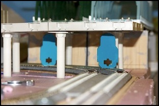
Viaduct Station - original version - You can’t really see it here, but the left end sagged somewhat, and got worse after I added the station platforms.
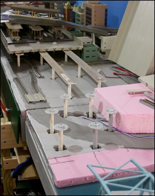
Station throat with viaduct removed, showing supports
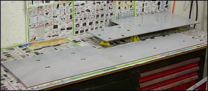
New hardboard supports being painted
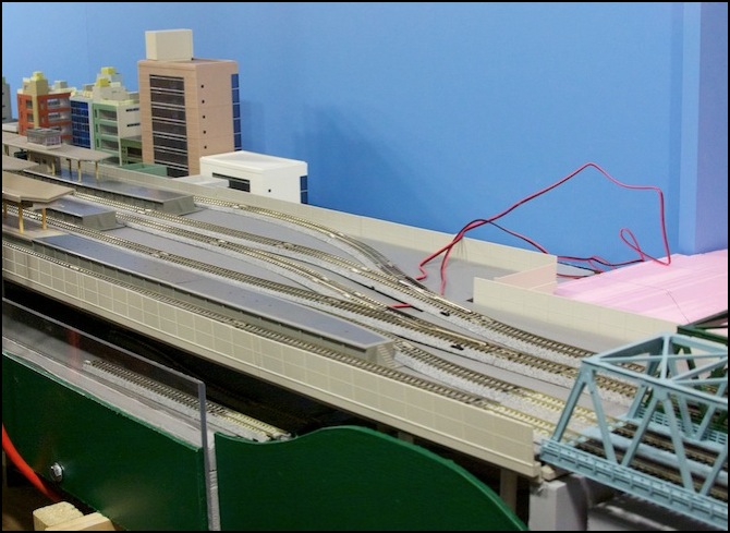
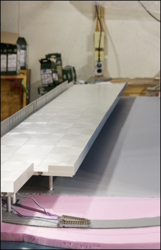
New viaduct assembly
