


Designing the Helix
The Helix is still in the planning stages. This page will be updated (and could be replaced) as I go on.
A Helix is a vertical corkscrew of track, used to move trains between two or more levels of a multi-level structure. The biggest problem with them is the amount of track used, which affects both cost and the time it takes a train to travel though the helix. Grade is also a factor, as steeper grades will minimize the number of loops in the helix, at a cost in decreased train length due to the effort required to pull the cars up the steeper grade.
When I originally designed the layout, I made provision for a helix to take trains down to hidden storage tracks under the Urban Station scene. This required a 16” drop, or about 5.5 turns of the helix. I’ve since freed up some room to one side of the layout, and now I’m considering creating a visible yard scene with storage tracks. This would be somewhat limited in length, and unable to store Shinkansen or 15-car commuter trains. But such a yard should be able to handle typical 10-car commuter trains as well as shorter limited express and “Joyful” trains. I’m also planning to add scenery in the form of a “cap” above the helix, removable for maintenance purposes (although normal access to the helix would be from the middle or sides). This has revised the design somewhat, and the new helix needs to drop about 9” in 3.25 turns, or 2.75” per turn. Which, thankfully, turns out to be a good choice due to other constraints as well.
Actual construction of this may not start soon, as I have many other things to work on, but the design has been roughed in and various measurements checked (I even bought a few sections of the needed Tomix track to verify sizes). I wanted to get the new storage tracks designed before beginning construction also, just to ensure I am actually going to be able to store enough trains in the space available to make it worth moving the storage tracks. However, even if I build the helix as described, the method will allow the helix to be extended if I later decide to use the under-table location instead (unfortunately there isn’t enough space in the helix to do both; there’s no way to branch even one track off halfway down).
Designing the Helix
I went through several stages of design. The first planned to use simple flex track on a wood support. This has the benefit of being well-proven. It has the downside of requiring a fairly substantial structure (even thin wood isn’t all that thin, and is heavy). And more importantly, it’s a fair bit of work to make one that way. If there’s an easier method, I have better things to spend my time on.
My plan for this was to use two overlapping layers of glued 1/4” plywood to form the helix as one continuous length of wood. Threaded rods would run vertically through both the inside and outside edges of this, with nuts allowing the grade to be precisely adjusted. The rods would have been fastened to a fixed base assembly, and the whole helix would rest atop (or be bolted to) the support framework, allowing it to be added after construction on a workbench, and to be separated for an eventual move. Access to the helix to clear derailments would have been from inside (again, reaching in from the outside may be more practical, except at the top where it sits inside the mainline and subway loops).
The revised design ended up keeping the basics, but replacing the wood and flex track with sectional double-track viaduct segments.
Sectional Viaduct Track for a Helix
While researching helix construction, I read about someone with a helix built using Kato Unitrack Viaducts. He cites as inspiration a picture in the NMRA’s Layout Design Special Interest Group’s Layout Design Journal, but doesn’t specify issue or page. With five and a half turns, my original design wouldn’t have been cheap (about $300 for Unitrack, versus about $125 for Micro Engineering flex track). But it would certainly have been easier to build than flex track. The vertical spacers are Plastruct square tube cut to length, fitted over 1/8” square brass stock that runs up through the catenary cut-out holes in the viaduct (a very elegant design). One advantage of the viaduct, aside from the ease of assembly, is that it comes with built-in walls to prevent a derailed train from hitting the floor. Given the cost of these models, such a wall is necessary, and I’d planned to build one.
His helix used a 2.5” lift per loop (it was oval shaped, so overall it had a 2% grade), so the spacing I’d planned originally would have been possible. There might have been a bit less clearance due to the thickness of the viaduct, but it was about the same.
Unfortunately, Kato’s older non-superelevated viaduct curves aren’t available anymore and I couldn’t find enough of the old stuff to build my helix. Using the new version and having the train lean inwards on the curve would make cars more prone to falling over. For that reason, at first I decided to go back to my original idea of using flex track on the helix.
Tomix Viaduct
After some more thought, I realized that Tomix still made non-banked viaduct. It lacks the mounting holes, so the simple Kato approach wouldn’t work. However, 1/4” threaded rod outside the viaduct, with 6” lengths of thin metal between them, all supported by nut/washer sets, would do. I set about planning this, thinking to use 428/465mm viaduct (which is available in both ordinary and slab style, see my Tomix FineTrack page for more info). And I was thinking about using the slab style, as it has removable sidewalls (which might help in cleaning and fixing derailments) and uses “from below” low-profile power feeders, which I expected would be easier to use than the usual “from the side” Tomix design.
Unfortunately, after I bought a few lengths of track and test-fit them (before building anything, thankfully) I realized that while I had plenty of clarance lower down, at the starting point I was constrained to a maximum outer diameter of 36.5”, due mainly to the placement of the subway track return curve. Moving that wasn’t really practical (it was where it was due to the way the support was constructed, which in turn derived from the outside width of the tables and the placement of the subway track along them). That was unfortunate, as 428/465 is the smallest radius of slab track, and I really wanted to use that due to the low-profile power feeders (to say nothing of the grade provided).
Stepping down to the next-lower radius (354/391mm) meant changing to the non-slab viaduct. It also meant a steeper grade. Finally, while this viaduct has a cutout under the rails that looks like it could take a power feeder, it doesn’t appear to be designed for use with either the standard or the slab-rail versions of the feeder (and the Japanese descriptive text about power feeders is ambiguous in translation; I expect I’ll buy a couple and see what I can do).
If I were designing from scratch, I’d ensure I had space for the 428/465mm slab viaduct, which needs about 40” clearance side-to-side once you take the outside positioning of the support rods into account.
Read on for a more detailed explanation of what factors influenced the overall design, and what the final design gave me.
Helix Design Issues
A number of factors went into the helix design. Some of these were considered before the original layout design, and guided its shape, others were only considered later when planning the details.
Diameter and Circumference
Ideally, a helix should have a large diameter. This is because a larger diameter means a larger circumference, and it’s the ratio of rise to circumference that defines the grade within the helix. For a 3” rise with a 2% grade, the circumference of the inner track would need to be 150” (59 cm), and thus the diameter of the outside (assuming two tracks and some margin for support) around 51.5” (1.3 m). While I wanted to keep the helix at 2%, and have a 3” drop between loops, that’s not a practical size for this layout.
Narrower diameters not only require steeper grades, but sharper curves, which can increase derailments as trains are pulled sideways towards the center of the circle, and once one car derails often a large part of the train just falls over (called "clotheslining"). Protective walls are needed to prevent trains from taking the long fall to the floor in any case, but derailing trains inside a helix is going to be a mess to clean up no matter what, so a large radius to minimize this problem is also desirable.
The diameter of the helix is constrained by the space into which it must fit. I didn’t have room to place it outside the bounds of the layout, so I needed to fit it inside the roughly 50” overall width of the layout. And since it was starting at the same level as the subway line, I actually needed to reserve several inches of that for the subway tracks and the structure supporting their roadbed. I designed the layout assuming the helix would fit within the bounds of the “unsceniced” return loop at one end of the layout (see the track plan, with the right end showing an early helix in blue).
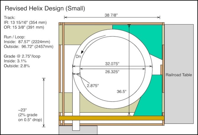
This left me with a hole about 39” across, of which the outer inch on each side was assumed to be consumed by bracing for the helix, leaving me 37” overall (94 cm) to work within for the track. This meant my outer track could have at best about an 18” radius (457mm). This turned out to be overly generous, and on later examination I found the actual helix would be constrained a bit more than that, and that I needed more room for the viaduct itself. This provided a 36.5” (927 mm) maximum outer dimension. The larger viaduct I’d wanted to use wouldn’t fit in that, and I was forced to step down to a smaller size with the radius of the outer track at just 15 3/8” (391 mm).
Maximum Grade
Related to the diameter of the helix is the grade created within it. If trains won’t climb that grade, there’s no point in building the helix. Kato describes their trains as capable of climbing a 4% grade (a rise of 4 inches in a run of 100), and their inclined pier set used with 248mm straights produces a grade about this steep.
Two factors argue against making a helix this steep: first, there is additional power required from the motor when climbing on a curve (meaning a train that climbs a 4% straight may not climb a 4% grade on a curve), and second the additional resistance of a longer-than-average train needs to be allowed for. And I may eventually have non-Kato trains with less power. My design goal was to try for a 2% grade, and to keep it under 3% in any case. This is steep compared to what a helix for freight use would normally use (likely between 1% and 2%, to reflect prototype mountain grades).
With the reduced-size viaduct, the 2.75” separation between levels I’d planned for the new storage access would provide a grade of 2.8% on the outer (ascending) track, and 3.1% on the inner (descending) track. This also gave me a 2” access opening on the side to fix derailments, and a 2.25” internal clearance, more than I really needed.
Direction of Grade
Since Japanese trains run on the left, the helix is arranged to spiral up to the right (a clockwise rise), this is the opposite of how a double-track helix is normally built for US-based railroads. This provides the longest track (the outside one) and the lowest grade for trains climbing the helix, although the difference is slight. This affected where the connection to the upper-level track would be, and where the storage tracks would be located, so it was actually planned in advance of the finalization of the track plan, long before the dimensions of the helix were worked out (something I put off for a couple of months for even the initial design).
Helix Support
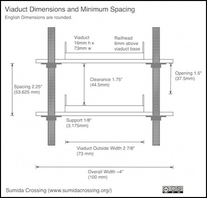
The basic idea of the support is that I’ll use two-foot lengths of 1/4” threaded rod. At the bottom, these will be attached to a couple of boards laid across the supports. These will go up inside and outside the viaduct in pairs. Between a pair of rods (one on each side of the viaduct) a short length of thin sheet metal will be laid, resting on nut/washer combinations on the rod. The viaduct will be supported on the metal, and the nuts can be adjusted for height. It’s not quite as elegant as the Kato Unitrack would have been, but it should work.
To support each 45-degree length of viaduct at the ends, sixteen rods will be required (8 inside the helix, 8 outside). To ensure minimim clearance of 1.75” between the underside of the supports and the railhead, a 2.25” spacing is required. That’s considerably less than the 3” I’d been expecting to use. However, this only leaves a 1.5” (37mm) opening on the sides for access if there is a derailment, so a larger spacing is still desirable. As noted above, I added a half-inch to this for my actual planned spacing, increasing the grade but improving the access and clearance.
Revised Design Summary
The original storage tracks were to be hidden under the Urban Station, and this required a 16” descent over about 5.5 loops of helix. This had the benefit of allowing storage of very long trains if desired, although I only built two 48” tables for this purpose (I could extend another 48” below the River Crossing scene).
With the change in design, and the reduced drop per loop, I now had the risk that the track wouldn’t descend far enough to clear the wood holding up the tracks leading to the upper end of the helix (the upper green section in the diagram at the top of the page). It needed to descend at least 1.75” plus the thickness of the wood (0.5”) in the first 7/8 of the turn. With a 2.75” drop per loop, my clearance should be 1.9” (48 mm) less the thickness of the viaduct base (6 mm), or about 1 5/8” (42mm). That’s a hair under 1.75” (44.45 mm), but I think it will work. If not, I’ll need to do some re-engineering on the wood. Because the track is on adjustable supports, if I have an issue I can also change the grade on the helix as long as I figure this out before finalizing the placement of the storage tracks.
The resulting 2.8% grade is a bit steep, but within my minimum, and I’m fairly confident that any reasonable train can climb a 3% grade on a curve. I could be wrong, but there’s no easy way to test that short of building a helix with enough turns for a long train. So I might as well build the real one. If I’m wrong, at least it should work for short trains. And the supports will allow adjustment, so I could reduce spacing and lower the grade if necessary (although that can force other changes).
With 45-degree segments, the track can be insulated eight times per loop (every joint), with a feeder on each track segment if I want. Even if I don’t wire up that many occupancy detectors, I’ll probably have lots of feeders for reliability reasons. At each end, I’ll need to adjust the spacing between tracks, because Kato and Tomix use different separations, but short lengths of flex track should be able to deal with that problem.
Unfortunately, I did make one mistake at some point. In the diagram at the top of this page, the green block at the bottom is the extension I added to the Urban Station scene. The helix passes under it with about 1” of clearance at the start due to a miscalculation. Fortunately there’s nothing on it aside from some foam, and it’s removable, so I can cut it down. Unfortunately, the underside is presently holding a couple of terminal strips and a bunch or wires, which will need to be relocated. But otherwise, it looks like the Tomix track will fit, just barely.
Revised Storage Tracks
As noted above, I freed up some space in the basement off to one side of the layout, and this allowed for visible storage tracks up to about 80” (just over 2m) long. Actual train length would be shorter, as some of that needs to be the yard ladder. This will let me create a visible yard scene for my storage tracks. It also only requires about a 9” descent, in 3.25 turns, which reduces my cost significantly.
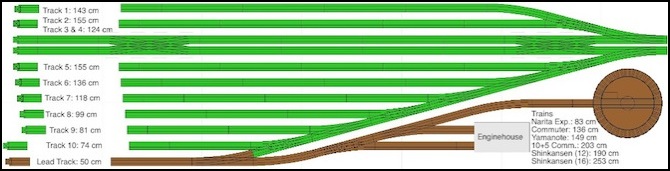
Sample Yard Design
The above diagram isn’t final. It’s just a placeholder to see how much I could fit into such a yard using ordinary Unitrack (I might also use finetrack for the yard, as an experiment). It’s somewhat limited in terms of train length, but I can fit a sufficient number of 10-car commuter trains (four) to provide variation on the main commuter line. There is also space for three additional short trains (up to about 6 cars) and perhaps some additional freight units. It’s not as comprehensive a yard as I’d like, but I think it will be good enough to be worth doing.
Parts
The important part of this is the Tomix Track. I’m going to need 13 sets of the #1162 Viaduct Curved Double Tracks DC391-354-45(F) track, at the US$12.62 current price that works out to $164 before shipping.
Beyond that, I’ll need sixteen to twenty two-foot threaded rods, fourteen to sixteen horizontal supports (actually cut from longer lengths of stock) and 28 - 32 nut/washer sets. I probably have the nut/washer parts already (I bought large boxes of both when working on the elevated station supports) but there’s a bit of cost in the other parts. I haven’t decided how I’ll support the last bit of straight track leading to the yard, which is why the above counts are not exact.
And finally, I need to figure out some kind of base to which the rods will attach, which holds the whole assembly up by resting on the sides of the support structure for the layout while at the same time leaving the center open for access to get inside and clear derailments (26” is tight, but I should fit, although after deducting support clearance perhaps not).
