


An Arduino DC Train Controller
I had a very simple problem: I needed a back-and-forth DC controller to run a tram line (aka, light rail line, in Japanese: 路面電車 or romen densha, literally “road surface train”, often translated simply as streetcar, even though the remaining two lines in Tōkyō have very little in-street track). But most of the devices on the market assume a simple single-tram, single-line arrangement, and none of the ones that don’t assume shared tracks, at least not in the form I need. What I want to model is a line with two running tracks with double-track mid-line stations and a single-track station at each end. Both of the surviving light rail lines in Tōkyō are built this way: the Toden Arakawa line and the Tōkyū Setagaya Line.
After I started, I realized that I could use essentially the same circuit to model a single-track line that used a double-track station in the middle for two trains to pass. This would be appropriate for a number of smaller rural lines operated by one or two-car DMU (diesel multiple unit) vehicles. So this is actually a fairly flexible design, and not limited simply to light rail vehicles. I started building a simile diorama layout (my One Point Five Meter Line) using this approach.
While these pages are the most up-to-date material on the project, as well as holding the most detail, the blog posts (Musings) I made regarding the project as it unfolded may also be of interest. Those are collected under the Tram Controller categroy. I also have some pages covering the basics of using an Arduino for model railroad projects that might be useful to read.
A number of the diagrams from these pages are available in larger 800 pixel versions in the Arduino Diagrams album.
Note: at present this project is once again stalled, partially because I’m not working on either layout that required it and I’m not sure if of when I will. The motor control library was completed and published, see the bottom of this page for location. This won’t run a train on its own, but provides the needed capabilities to manage a motor shield as a throttle with direction and momentum.
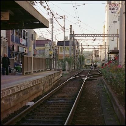
Minowabashi Station, Toden Arakawa Line (2009)
From Flickr, Photographer: haribote
Eventually I hit on the idea of using an Arduino equipped with a “Motor Shield” (DC motor controller for Arduino) to run two vehicles back and forth on such a track. I could have used a fancy computer-controlled DCC system, but then I’d have to convert all my trams to DCC. And for this application, DCC is a bit excessive and costly; most of the capabilities I’d gain I don’t really need.
Credit where it’s due: I took the idea of using IR emitter/detector sets (i.e., a LED/phototransistor pair) from a comment on the Modelrail Otenko blog about the author’s experience using these for distance sensing. He also has a post with basic information about using Arduino for train control which probably planted the seed that became this project. His goals are more lofty than mine though: I just want a simple out-and-back controller customized to a particular type of vehicle and speed range.
Warning: The Arduino uses Pulse-Width Modulation (PWM), a type of pulsed power, to control DC motors. This is fine for most motors, but “coreless” motors run at low speeds on pulsed power can overheat to the point of self-destruction. Most DC train motors aren’t coreless, but I’ve heard rumors that Kato’s Unitram motors are coreless. These are ultra-small motors developed to make cellphones vibrate by spinning a weight at high speed for a short time. I’m setting my program up to use “ultrasonic” PWM (which is not the default on an Arduino), and that should avoid problems with coreless motors. But if you’re using Unitrams or other coreless-motor designs, you’ll want to be careful.
Overview
To do this I need some way to use DC that provides for two independently-controlled low-amperage voltage-controlled power supplies of roughly 0 - 9 V DC (I don’t need these things to run too fast), and some way to selectively switch the two end stations between them, as well as independently controlling the voltage on each. I also need to have some position-detection capability, so I can stop trains in the station, and know when a train is approaching the end of the line.
What I’m using for track is Tomix’s FineTrack MiniRail PR140-30 switches and C140 and C177 curved track (more info and photos). The radius (140mm is about 5.5 inches) is wide enough that an articulated tram can negotiate it, but sharp enough to look “realistic” as a tram line next to other train tracks with gentler curves. There’s a wealth of information about using this for light rail modeling at the EasyTrolley website.
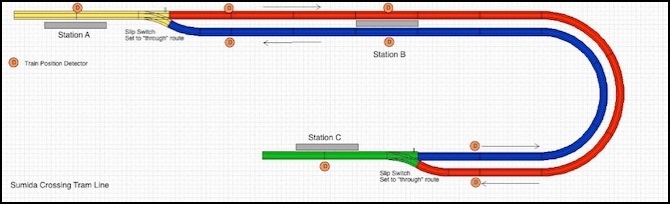
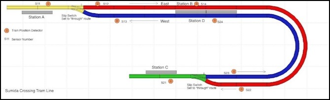
One of the nice things about this is that these switches are “slip switches”. This means that a train can run through them the wrong way without derailing. For example, in the picture below, the switch adjacent to Station A will be set to send outgoing trains to the red track, and never changed. But a train approaching on the blue track can run into Station A with no problems. It’s not all gravy though, these switches are built with power routing circuitry that only works if the switch is thrown, and if you’re entering from one track and the slip switch is thrown the other way, there’s a short dead zone on the track. A vehicle with pickup on both wheelsets will bridge it, but one with single-truck pickup is likely to stall, particularly at low speed.
The trams I’ll use, at least initially, will be my Modemo Tōkyū Setagaya line two-car articulated Series 300 cars. I have several of these, so I can vary the ones running at any given time to add yet more variety (I don’t have room for a mid-line depot, otherwise I could do even more). I also have some Arakawa line trams, and one Kato Unitram, just to add some variety.
If I just wanted to run one tram at a time, a simple out-and-back controller would work (you can buy these relatively cheaply, such as this one or this one, or I could even build my own). But what’s the point of double track if you don’t have at least two trams? I want this line to look realistically busy. I could eliminate the single-track stations and just run two parallel lines, but not only would I double the electronics cost, I’d lose the “left hand running” of the prototype system, and that’s part of the character I want to capture. Ideally, what I want are two trams running back and forth and stopping at all three stations, pausing, and then continuing, without ever hitting each other.
The tram line is actually part of the Urban Station scene. It runs along the back behind the buildings (almost totally out of sight, unfortunately) and then curves across the road and under the viaduct station, so that station C is near the front of the layout, adjacent to the subway tracks.
Urban Station Scene Tram Line Diagram
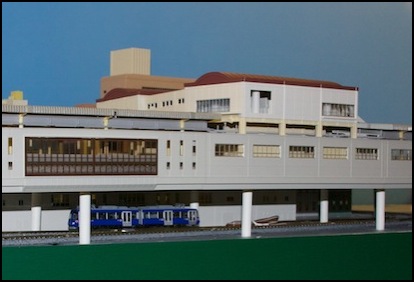
Tram at station C
Now to make this work, the yellow and green tracks in the diagram above need to switch to match the polarity and voltage of the track that the train is running to/from, and some ability to detect train location is needed. For example, a train approaching Station A on the blue line must not enter the yellow station track if there is another train on the yellow track, and the yellow track must change to the “blue” supply before it can enter. Similarly for the train to depart, there must not be another train on the red track and the yellow track must switch to the “red” supply.
The Station A (and Station C) power supply selection is done via a relay, where a signal causes “Red” to be selected, and the absence of a signal causes “Blue” to be selected (and the opposite for Station C). Stops will just be done by gradually adjusting the voltage to zero, for realistic “slow down then stop” behavior, when the detector registers the train’s presence in the station. The detectors just short of the station will allow a train to be held while another is in the station, or to be slowed from “track speed” to “entering station speed” before negotiating the switch. Similarly a departing train can be kept at a lower speed until it clears the switch, then that detector can allow it to be set to “track speed”.
Train detection is needed at the following eight locations: Station A, Red track at Station A switch, Blue track at Station A switch, Station B Red Track, Station B Blue Track, Red Track at Station C switch, Blue track at Station C switch, and Station C. With that, trains can be stopped in stations and approaching the switches, and we’ll know when a departing train has cleared the switch. Detection could be done with block occupancy detectors, but those are relatively complex. A simple photocell (using ambient light) could be used, but a better method is to use an LED/phototransistor emitter/detector pair, which allows it to work regardless of ambient light, for night running and operation below the viaduct station.
Further, I’m going to set up four station-exit signals (one at each station) and two station-entry signals (one on the blue line just before the switch to Station A, and on on the red line, just before the switch to Station C). These will be simple red/green signals with two separate LEDs on a mast (likely NJ International #2004 signals).
I’ll also add some kind of manual override to allow using the power to position trains before starting automatic operation, although initially I’ll depend on putting things on the track in the right place by hand. And I’ll include a pair of potentiometers to allow “track speed” to be adjusted individually for each tram (not all of my models will work the same).
Enter Arduino
After thinking about this for a long time, during which I’d read several articles and websites about using the Arduino microcontroller to operate DC motors in robots or to act as a DCC command station, and even as a DC throttle for a train, it finally hit me that it could also be used to automatically control DC trains (yeah, I’m a bit slow on the uptake). The Arduino is designed to be used by “artists, designers [and] hobbyists” according to its website. And that’s reassuring, as while I used to do a fair bit of programming, I find the semiconductor electronics side a bit daunting. But fresh off designing my car lighting system, and assembling a DCC booster kit this didn’t seem overwhelming.
There are a number of different Arduino models to choose from. But there is an important software difference between the ones I’m looking at and older designs: the newer ones don’t require driver installs on the computer used to program them. So I limited my choices to the newer ones.
Due to some issues around which Motor Shield I was going to use (see the Shields page for information about compatibility) I decided to use an Arduino Uno, as this was relatively inexpensive (US$30) and easy to find (Radio Shack sells them). This, however, turned out not to have enough control lines (pins) if I wanted to add signals, so I switched to use of an Arduino Mega 2560 (US$59). I actually ended up buying both (and several others besides) along the way, so I’ll need to eventually find something interesting to do with the smaller ones.
Assuming this all works out (and so far it seems to), I can see wanting to do other things with Arduino in the future. It’s a very flexible little controller.
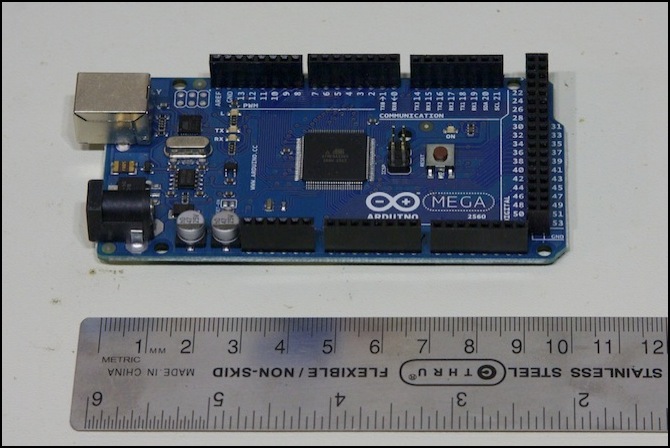
Arduino Mega 2560 (original version)
You can do some limited DC motor control straight off the Arduino board, or build your own motor controller if you need lots of power, but I also discovered that there is a “shield” (an add-on board) called the Ardumoto ($25), which can operate two DC motors at “up two 2 Amps each” (we’ll come back to that claim later). One thing to be aware of: this board comes without the screw terminal connectors or headers to attach it to the Arduino. That’s fine if you want to place one remotely from the Arduino and solder wires to it (as many do), but for my purposes I wanted to attach it directly and piggy-back off the Arduino power supply. What I should have bought was the Retail version ($30), which comes with the needed parts (some soldering is still required, but if you’re afraid of a small amount of soldering, this isn’t the project for you).
Actually, there are now (2013) a number of shields available, and you can find some of them at the local Radio Shack. My Survey of Shields page has more information. I still ended up back with the Ardumoto shield.
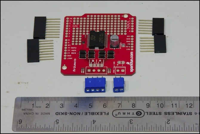
Ardumoto Shield with headers and screw terminals
Well, that’s not everything, as I also need a pair of DPDT relays (or four DPST relays), and eight IR emitter/detector pairs. I’ll come to those later. Total cost for the installed system should be about $100 with all parts included (see below).
Parts mostly acquired (Feb 2011), I started in on detailed planning, after discovering I had bought the wrong relays. I also didn’t like the first detectors I bought (which were oriented to receive light from above, and I found some that faced sideways instead. Then I stalled out, and didn’t return to the project for two years.
Power
The Arduino can run on a variety of voltages, but less than 7 or more than 12 can cause problems. I’m going to use a regulated 12V supply, since I can get one from Sparkfun cheap. If it wasn’t regulated, I’d use a 9V supply to be safe. I may also wire the motor shield to the layout’s 12 volt electronics bus. The 8 IR LEDs don’t have to connect to the Arduino at all, just a supply voltage, and I’ll likely use one of the layouts lighting or accessory supply lines for that.
Stalling Out
At that point, the project stalled for about two years while I worked on other parts of the layout. I did however connect my Arduino up to a computer and download my first example program (the “Blink” program), and play around with modifying it to learn the programming/downloading interface. Except for the fact you program it in a language very much like C, this is really easy to use (programming in C isn’t that hard, but there are easier languages for hobbyist use and I’m surprised they aren’t using one).
Note: it is C actually, or rather C++ an object-oriented dialect of C. Still, they make it quite easy to use, and there are reference pages and lots of information for beginners on the Arduino site. Don’t be turned off by the programming aspect. While complex programs are just that, complex, there is a lot that can be done fairly easily, especially if you can start with a program or example that someone else wrote and customize it for your needs. And lots of people post Arduino programs on line (Google for the word “Arduino” along with other phrases). I’m putting my programs up for others to use, see the links at the bottom of this page.
Returning to the Project
After a long delay, I resumed work in April of 2013. I had some new ideas (not all of which worked) and since then I’ve been working on this fairly regularly, one part at a time (I spent most of April and early May getting the motor controller working, then I spent the rest of May and all of June getting the sensors to work, early July went to some work on controls, before I took a short break, and in late August resumed working, starting on multiplexed LED signals. September went mostly to the signals, and to beginning to put everything together into the actual Tram Controller program. With each phase, I did short little test programs (some of them I’ve made available online since I think they’d be useful examples, see the software section at the bottom of this page). The important code from those test programs will eventually find its way into my Tram Controller program or the libraries used by it.
Radio Shack stocks Arduinos these days, and along with them are a couple of motor shields. One is an Arduino design similar to the Ardumoto (part 276-131, apparently now discontinued), and the other is from “seeed studio” (part 276-242). This is seeed’s version 1 shield, which is nice in that it has a very large heat sink, and uses a better selection of pins than the Ardumoto (avoiding the Timer0 conflict that shield has on the Leonardo). I’d planned to use the V2 version of the seeed shield, but unfortunately it has some kind of design flaw when used with an external power supply (exactly why I’d wanted to use it) and I managed to fry mine. Back to the Ardumoto shield for me.
One downside to the seeed was that while their V1 shield is available in the U.S. at Radio Shack, the V2 needs to be ordered from their website, and so there will be a shipping charge from China (which is quite high unless you want to wait several weeks for delivery, and I’m always impatient). So I had to wait, and pay extra, only to have the darn thing go up in smoke. Some days are like that.
Updated Parts List
This is my current (likely not final) parts list, excluding track and wiring:
Arduino Mega 2560 (Sparkfun DEV-11061) @ $58.95
Ardumoto Shield (Sparkfun DEV-09815) @ $24.95
Stackable Header Kit for Ardumoto (Sparkfun PRT-10007) @ $1.50
Two-pin, 3.5mm pitch, screw terminals (Sparkfun PRT-08084) (2) @ $1.25
Power Supply (12V, 600mA) (Sparkfun TOL-09442) $5.95
5V DPDT relay (Tycho IM23TS, Digikey PB1169-ND) (2) @ $3.19
Detectors (Sparkfun SEN-00241 the Digikey 160-1065-ND & 160-1063-ND). (8) @ $1.95 or $1.05
Total: US$108.63
Note: you can get the Detectors from other suppliers like Digikey for about half of what Sparkfun charges. You’d need to buy a lot for the extra shipping to be worth it, or be buying other parts though. I also managed to find the Mega 2560 R3 locally (in a “Made in Italy” official Arduino box) for US$35, barely more than the cost of an Uno. I bought two.
Design
My design for this is relatively straightforward. The Arduino controls the two throttles, stepping speed up and lowering it down for a reasonable departure and arrival performance, and a fixed top speed appropriate to the trams. It will also select which power supply is in use by a section of track, Eastbound or Westbound (which I’ll abbreviate to “E” or “W” from here on). And all of this will be coordinated based on inputs from the train detection sensors so the trains stop at the station platforms and don’t hit each other at the ends. When trams are moving in one direction, they will be connected to the E power supply, when they reverse and head in the other direction the same tram will be connected to the W power supply. Thus the two power supplies never actually need to change polarity, and I could have wired things to save myself the need to use the two direction-control pins if I’d wanted to.
As noted, I’m using a shield (circuit board) to provide the two power supplies rather than building my own power amplifier circuit. The Ardumoto shield uses two of the Arduino’s digital output pins per motor output: pins 3, 11, 12 and 13, while the seed shield uses a slightly different approach with three pins per motor. Each motor has a speed pin and one or two direction pins. Maximum amperage is relatively low (although the seed could probably drive a pair of small HO motors). My needs are well within even the Ardumoto’s safe bounds, which are around 600 mA total current without some kind of added heat sink.
I’ll use some relays to switch the track in the two stations between the “East” and “West” motor supplies. The east and west motor outputs never change direction, and are always connected to the east-running and west-running tracks respectively. This design could actually allow me to run three trams: one in an end station, and one running on each of the running lines. When a tram enters the empty end station, the tram at the other end can start down the line, and the tram on the other running line will be able to enter the now-free station, clearing its line for the tram at the far-end station, and so on.
But to make it work, I need to know where the trams are, and that means I need sensors. And because I want the tiny plastic people driving the trains to know when it’s safe to leave a station or enter then end stations, I’ll need some signals. In the schematic diagram below, O1 to O8 are the optical detectors that let me know when a train is passing a certain location, and S1 to S6 are the signals (all are two-color red/greed except for S2 and S5, which will be three color signals but will only ever display yellow or green.
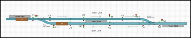
Simplified Track Diagram showing sensors (On) and signals (Sn) as well as two trams (T1, T2)
Sensors
Sensors are actually fairly simple in concept, but to use them efficiently, I’m going to complicate the design a bit.
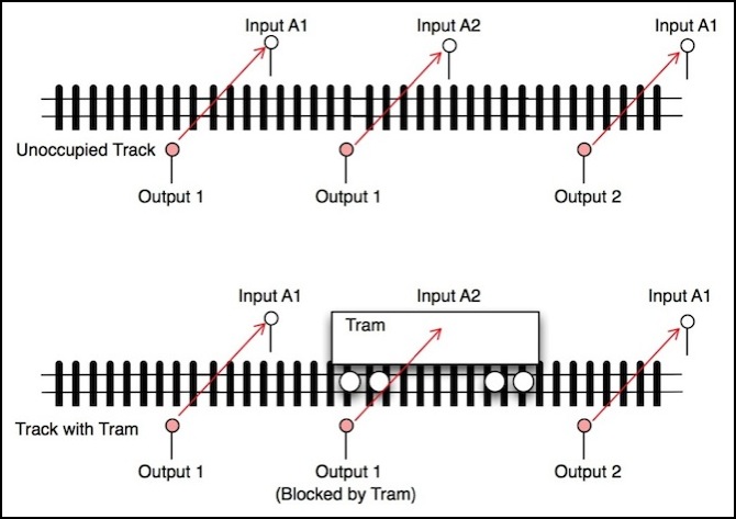
First the basic idea: to know where a tram is, an infrared LED (emitter) is placed on one side of the track, level with the body of the tram. On the other side of the track a phototransistor sensitive to infrared light is placed. Using infrared makes it less likely that sensors will be confused by room lighting (well, not really, that turns out to still be an issue), and using an emitter/detector pair makes calibrating the sensitivity of the sensors simpler, and also allows them to work in dark areas such as underneath the viaduct station.
But because I need 8 sensors and the Arduino is limited in the number of analog pins, I need to multiplex them. I can share the outputs and inputs between multiple sensors in a way that will allow me to read one at a time, while using as many as the product of the pins. My original plan was to use four outputs and two inputs to control eight sensors. If you need to multiplex a lot of inputs (or outputs) there are specialized chips that reduce the number of required pins even more, but I don’t need that and I want to avoid unnecessary electronics (just one more thing to get wrong). For simplicity, and because I had enough pins, I’m actually going to simplify this further.
There are some power limits to this I need to watch out for, which I’ll say more about later. Time is also a factor: although I’m working with relatively slow-moving trams, each sensor has to be on long enough to stabilize, and can’t be off longer than it takes the tram to pass it at top speed. That puts a bound on how quickly I can cycle through the sensors and how many there can be before the cycle time becomes long enough that I could miss one, which I’d need to determine by experiment if I were going to do a lot of these. Thankfully with only 8, I’ll be reading these far more often than I need to, particularly for slow-moving light rail vehicles.
Control Buttons
The controls are simple, and consist of two switches and two potentiometers. These are:
- Switch 1: Auto/Manual: In Auto model the controller is active, in Manual the auto-stop is disabled (see Throttle section below).
- Switch 2: Clear/Emergency Stop: immediately sets both throttles to zero without momentum when set to “stop”.
- Potentiometer 1: Set train A maximum or manual throttle (see Throttle section below).
- Potentiometer 2: Set train B maximum or manual throttle.
This doesn’t allow for manual operation. These controls only affect how the automatic operation is
Note that the Arduino will continue to run its program regardless of the button settings, it just won’t do very much when it’s in “park” or “emergency stop” mode.
Both of these have some implementation complexities. The potentiometer is an analog control, that need to be scaled to produce a 0-255 value, and it likely needs some smoothing as well. The switches need to be de-bounced. That topic is covered in the Arduino Buttons and Switches page in the Arduino sub-section of my Electricity for Modelers section.
One important comment about the way the motor shield outputs are used, and how this is affected by the potentiometers. Only the two end tracks switch between motor shield outputs, the middle tracks are fixed (that part of the Original Design diagram up above is unchanged). But each potentiometer affects the top speed of one vehicle. This means that the setting read from pot #1 will affect motor output A when that output is driving vehicle #1 (basically, when the tram is moving “east”) and motor output B when that output is driving vehicle #1 (when it is moving “west”).
Relays
A relay is a simple electromagnet connected to a spring-loaded switch. Off, it’s thrown one way by its spring, when power is applied the switch is thrown the other way by the electromagnet. A Double-Pole (DP) switch can switch two lines simultaneously, which I’d prefer for switching both tracks . It is also possible to use a single-pole relay and common rail wiring or even two single-pole relays. A Double-Throw (DT) switch has two “on” settings, allowing it to be used to switch between two inputs. So the relays I’d prefer to be using are Double-Pole, Double-Throw (or DPDT) relays to connect one pair of output pins (the track) to two different pairs of input pins (the East and West power supplies from the Ardumoto shield).
However, you can get relays preassembled on a shield. The downside is that instead of two DPDT relays you get four SPDT relays, so you have to throw each rail separately. That isn’t really a problem, since there should not be a train on the track when you switch the power supply to that track. The upside is that the shield handles driving the relay using power from the Arduino’s power supply rather than through the Arduino pin. That’s important because a relay uses a magnetic coil and is a power hungry device. The model I’m likely to use (seeed studios version 2) has four relays that each use 72 mA when they’re in “closed” state, much more than the 40 mA limit of a pin. So if I were driving these directly, I’d need to rig up a transistor and use it to power the relay (which is what I expect the shield is doing).
This does take up to 250 mA of my power supply, which makes it, aside from the trains, the most power-hungry part of this system.
One downside to the seeed shield is that is does use the Arduino power supply, and the sudden change of two relays being thrown and adding 144 mA of load might affect other circuits.
Throttle
The original concept had a “one size fits all” approach to the speed the trams would run at. Along the way, I realized that this was a bad idea (due to gear-ratio and motor design differences) and that I needed a way to adjust the maximum voltage used for individual trains separately so I could speed-match them. This led to adding two potentiometers.
The potentiometer, or “pot” for short, is a device with three electrical contacts (a rheostat is similar, but has only two contacts; don’t use one of those by mistake). These are available in several types, and for this application the “linear taper” version is preferable because the numbers read by the Arduino are proportional to the distance the control is turned. For an actual throttle used to run a train directly, it might be preferable to use a “log taper” (aka “audio taper”) model, as these produce less change in the returned value for degree of rotation at lower throttles, and more at higher (see this excellent explanation of how they work), allowing for finer control at low settings. However, since my experience is that even slow speeds need a high setting (unless I want to do some additional mapping of the control) I’m going to use the linear version, at least initially.
At first I’d planned to use one pot (and thus one analog pin), with two buttons used to “learn” a top speed for each throttle from it. When button A was pressed, the pot would have been read to set the maximum speed for throttle A. When button B was pressed, it would have been read to set the maximum speed for throttle B. This, however, needs two digital pins, which were in short supply when I was designing for the Uno, plus one analog pin. I went to two always-active potentiometers (two analog pins, zero digital pins) as a result. Even with more pins, I think this is a simpler design in several ways, so I’m going to stick with it.
One reason for that was that I realized that this allowed a relatively crude manual control mode to be added as well since the pots would be always live and could be associated to one tram. Although I don’t have the extra pins needed for a pair of direction switches (well, I do now; but I’m not sure that I need them), I came up with a way to do without these. This idea behind this is that in “manual” the each pot will control the voltage for one tram. The auto-stop function will be disabled except at the end of line stations, but the sensors will still be live, and when a tram is in an end station, once the pot is set to zero, the direction is reversed. A “hold down” will be needed to keep power from being applied even if the throttle is turned up, until any tram on the track leading away from the station has reached the far-end station.
What this does is allow me to stop, or not, at intermediate stations. So, for example, I could add other “flag stop” stations that don’t have sensors along the line, and stop at them manually. Additionally, because the end-of-line auto-stop is still engaged, if I’m busy with one tram and the other reaches the end of the line it will stop rather than crashing.
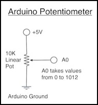
A potentiometer is one of the simplest Arduino controls to use. The outer two of its contacts are connected to the Arduino’s +5 and Ground pins to create a voltage across a resistor, and the middle pin, which is internally connected to a “slider” that moves along the resistor when the shaft is turned, is connected to an analog pin (I’ll use A0 as my example). When the analog pin is read, it will sense a voltage between zero (if the slider is at the ground end) and +5V (if the slider is at the far end). These voltages are reported as an integer from 0 to 1023. This will need to be scaled to the throttle range (0-255) and this value stored to serve as the maximum value for the train’s speed.
Here’s the essential Arduino code to read one:
const int MAX_POT = 1023;
const int MIN_POT = 0;
const int potPin = A0;
int readThrottle()
{
int th = constrain ( analogRead(potPin), MIN_POT, MAX_POT );
return( map( th, MIN_POT, MAX_POT, 0, 255) );
}
This defines a function which when read returns a number from 0 to 255 corresponding to how far the knob on the potentiometer has been turned. The MIN and MAX values can be changed if the pot you are using does not go all the way to 0 or 1023 (e.g., if you test it and it only goes to 1012, set MAX to that value and readThrottle will output 255 when the pot returns 1012).
While there are many different maximum resistance ratings for potentiometers, a 10 K ohm one is a good choice for use on an Arduino (the data sheet for the Arduino supposedly says “10K or less”, although I can’t find that statement, and higher ones may work acceptably; it’s likely the intent is to keep the pot resistance well below the 20K ohm internal resistance of the analog pin, to limit current). Values above 1K ohm will be more efficient of the Arduino’s limited power supply than lower values. If you use one rated 100 ohms, 50 mA will go through the pot, which isn’t a huge problem as the +5V pin is limited to the board’s limit of 500 mA (in some cases it can handle more). But it’s never a good idea to waste power if you don’t need to; you may need it for something else. I’m using a 10K ohm pot; they’re easy to find (Radio Shack 271-1715 or equivalent) and the best match for the Arduino’s requirements.
Note: some potentiometers come with a switch, which is thrown when the shaft is pushed in rather than turned. You could use this on a single digital pin as an A/B switch (for example as a direction control). If you do that, the circuitry may get a bit complicated, since you’ll need a pull-up or pull-down resistor to keep the input pin from “floating” when the switch isn’t thrown, and also a LED so you’ll know if it’s in the A or B states. That’s all feasible (and could even be fun to figure out), but I don’t have the pins to spare and I don’t need additional switches, so I won’t be doing that.
Signals
And then I decided to add signals. These will be multiplexed, with six two-LED signal masts driven by five digital pins. For more about how I’m doing this, see my Using LEDs with Arduino page. Unfortunately in doing this, I ran out of pins, and had to step up from an Arduino Uno to the Mega 2560, which has more pins available (at twice the cost, normally, although I found one on sale).
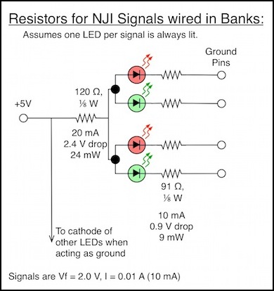
The LEDs will be be pulsed, but quickly enough that they appear to be always on. But at any given instant at most two LEDs will really be activated. The signals I’m probably using (NJ International #2004) use 10 mA LEDs, and I’ll light two at a time with the way I’m driving them, so this uses up (2 x 10 mA) = 20 mA of my power budget. The power dissipated in the resistors is tiny, so 1/8 W (125 mW) resistors could be used, but it will probably be easier to find 1/4W or 1/2W resistors, and those can be used equally well. Also, 100 Ohm resistors can be substituted for the 91 Ohm ones (91 is a standard 5% size, but may be hard to locate; I have a local store that sells them).
The actual wiring for this is “charlieplexed” rather than simply multiplexed, and rather complex. See my Arduino LED page for a full diagram. I’ll only be using the first six (or four for the One Point Five Meter Line) of the ten LED pairs possible with five pins. The software for charlieplexed LEDs is also more complex, but it lets me drive 12 LEDs with 5 pins, rather than the 7 pins a simple multiplexing scheme would require (or the 12 I’d need if I just wired them directly to ground). Since I don’t have to fit this in the Uno any more, I could have reverted to one of the simpler methods, but I expect I’ll use this technique again, so I decided to get it working now, so I’d know how it worked next time.
After some thought, I realized that the two signals allowing trains into the end stations ought to be three-light signals. They’d only ever display yellow (caution) or red (stop), and wouldn’t use the green, so electrically they’re the same as a two-LED signal. Ideally I’d make these four-light signals so they could display yellow-over-yellow on a single head (that’s a “speed restriction” indication, typically meaning a 25 kph limit), but unless I want to scratchbuild or hack a Tomix signal that’s not an option, so for now I’ll plan to use the NJI #2005, 3 color, silver, signal mast.
Summary of Controls and Pin Assignments
My current, and hopefully final, plan is to use an Arduino Uno as my controller, an Arduino Motor Shield, and a Seed Studios Relay shield (all presently available from Radio Shack, although the motor shields are on clearance and seem to be being discontinued).
The following pin assignments will be required:
Motor Shield: 3, 11, 12, 13 (Ardumoto shield)
Relay Shield: 4, 5, 6, 7 (seeed version 2 relay shield)
Sensors: 2, 10, A2 (16), A3 (17), A4 (18), A5 (19)
Throttle Pots: A0 (14), A1 (15)
Switches: 8, 9
Signals: (22, 23, 24, 25, 26 - on the Mega)
This design, before I added signals, used every pin on the Uno except 0 and 1, and those do double-duty for the Arduino’s serial driver, so using them can be problematic. When I decided to add signals, I had to switch to use of a Mega 2560 Arduino, at twice the cost. But now I’m not short of pins. I’ll still multiplex things; someday I may have a use for the other pins, so I might as well be efficient.
This is not by any means the only way to arrange things, it’s just what I ended up with.
Train Operating Logic
The Arduino has to follow some basic rules to make the trains run, which will be encoded in a program. The program logic really only needs to know about three speeds: stop (throttle at 0), “run slow” (throttle at a relatively low speed) and “run fast” (throttle at a scale 40 kph). However, the actual throttle output set by the program will ramp up or down between these values with some delay for realistic acceleration and braking using the momentum function of my library. As trains move down the line, they’ll pass or be stopped at occupancy detectors made up with simple infra-red LED emitter/detector pairs as described above. The program will react to these events (sensor becomes blocked, sensor becomes clear) by changing the throttle or power supply of one of the motor shield outputs, and possibly by switching one or both end-of-line stations to use the other motor shield output (which effectively reverses direction, since each motor shield ends up always being set for one direction).
As trains move about, they’ll be held at stations for a reasonable boarding period (tens of seconds). Because one train can’t be released from an end station until after the other train has arrived at the far end single track (two trains can’t share the same line) this will tend to synchronize the two trains to keep them as far apart as possible, although I’m planning to randomize the timers somewhat, so they don’t look artificially in sync.
Also, while I’m building this as a two-track line with stub end stations, nearly the same program will work for a single-track line with a mid-point double-track station. In this layout, a train can be moving over half of the track while the other one moves over the other half, going down to the end station, stopping and waiting, then returning to the middle. This is a reasonably typical design for a single-track branch line with a passing station in the middle, or the kind served by small one or two-car DMUs. That’s not what I want to model on the main layout, but I’m using that variant for my One Point Five Meter Line display layout.
The following diagram elaborates the plan some, compared to the original diagram at the top of the page. The sensors now have logical names, corresponding to the Sensor Design circuit diagram up above, and the middle station has been split into two stations since the two halves operate independently.
I’ve removed the high-level overview of the operating program that used to be listed here, as I’ve realized that it has some errors. I’m working on a revised design, but that will probably go straight to code (which will eventually be available), rather than being listed on this page.
Line with Sensors
Note that this way these tracks are arranged, a departing tram always uses the straight line out of the station. That isn’t required by the program or the switch itself, and I could have done it otherwise, but I thought this way looked more realistic.
PWM Frequency
PWM, as I’ve described before, has a frequency. When used in DCC decoders, there is a preference for “supersonic” frequencies, meaning 16 kHz in most decoders. That’s partly limited by the decoder clock speed, as putting a fast clock in a decoder raises the cost, and there are limited to the ability of slower chips to generate fast PWM signals.
But faster-clocked (higher-frequency) PWM has advantages. First, it keeps the motor’s armature saturated with current, which is both more efficient and produces less waste heat in the motor. For the typical motors I’ll use, frequencies “significantly above” 12 kHz are a good idea (12 kHz is the frequency derived from the time constant of the motor). Second, PWM will cause the motor to vibrate, and higher frequencies are harder to hear, and thus less distracting. That first point is particularly important for coreless motors, used in some model trains, as heating with low-frequency PWM can destroy the motor. Motor manufacturers often suggest that 20 kHz is a good frequency (significantly higher and you start to get into inefficiency from switching losses in the circuitry producing the PWM signal).
An Arduino, by default, produces PWM at 489 Hz. That’s very low, and a very poor choice for driving a model train engine. One thing I am doing is adjusting the timers of my Arduino to produce higher-frequency PWM (it’s a fairly simple software change, if you have the right model Arduino). It turns out the choices come down to 8 kHz, which I think is too low, 62 kHz, which is probably high enough to start seeing switching-loss problems, and 31 kHz, which seems like a really good frequency to me. This is covered in more depth on the testing page.
Because I’m changing the frequency, the pins used to output the PWM signals (Motor A PWM and Motor B PWM) to the motor shield can’t share the timer used for internal system clocks (Timer0). What this means in practice is that Arduino’s based on the AT MEGA 126, 328, and 2560 need to be used if you’re using the Arduino or Sparkfun Ardumoto shields, and that Arduino’s based on the 32U4 chip (Leonardo among others) can’t be used. This is discussed in more detail in the README file for the TrainMotor library linked below.
Stalling Out II
After a burst of activity that ended with the completion of the TrainMotor library, I set the project aside again. Actually, I’d completed a substantial portion of the control program, but not to the point where it actually did anything. And I’d run into some issues with my sensors I wanted to work on before I continued, but never actually did. Someday I’ll go back and finish those up, and then probably work on the controller again, but as of mid-2015 it’s been on hold for over a year and a half. What’s described below is the current state of things.
Software
For the moment, all I have is a test program that moves a small loco back and forth a few inches on one track using 31 kHz PWM. It’s a proof-of-concept for the PWM throttle at this point. I’ve started work on the actually controller program, which borrows heavily from various test programs I’ve written already, as well as using the TrainMotor library I wrote. When I have that working, I’ll update this page and post at least one Musing to describe what I’ve done.
Proof of Concept Test Program
Both motor shields (Arduino/Ardumoto) work on my Mega. The Seed shield worked until it fried itself. I’ve put the source for my original test program up on my site, just unzip and save it to a place where you can open it from the Arduino application. It’s defaulting to the Ardumoto shield, and you’ll need to change a constant to make it work with the seeed shield. It’s also only tested with the Mega 2560 (which should work for older Megas as well).
It starts with a delay of several seconds, to let you start the serial monitor, before activating the throttles. The throttle values are fixed (edit the main loop to change them). All it does is move the loco back and forth about 8” (20 cm). It will output messages to the serial monitor explaining what it is doing. If you try to run it on an Arduino it doesn’t support, it will blink the pin 13 LED in an SOS pattern.
I will warn that this is really, really, alpha code. I’ve only tested it with my sacrificial B23. If you run it with something valuable, and it bursts into flames, don’t blame me. That said, you can download it here. But you’re probably better off getting the Train Motor library and its example problems discussed below.
Note: the original program as written only compiles on the Mega. I should have tested that, even if I didn’t have a working model of anything else to load it into. There’s code in there to build it properly to run on older 168/328 Arduinos as well as the new Leonardo, but that turned out not to be quite right.
Sensor Demo Program
I also have a demo program for the sensors now (download it here). This has been tested on both my Uno and Leonardo, but all it does is scan up to four sensors and report when they transition up or down. See the Sensor Testing page for further info. I’ve made a number of improvements to the sensor code since that was published.
Signals Demo Program
I created a short program to test (and illustrate) the “Charlieplexing” method I will be using to multiplex the signal LEDs. That’s available (download it here) if you want to see it. This is described on my Arduinos and LEDs page.
I elaborated this into (and even published) a complete library for Charliplexed signals, which is described in a Musing.
Simple Throttle Test Program
I wrote a simple one-train manual throttle using one of the two motor controllers on a shield. This is a very basic wrapper, with most of the functionality other than the controls written as a separate library (based on the proof-of-concept program noted above). Because I think this might actually be useful to other people, even if it really is still “alpha” code at this point, I’ve put it online via a source-code sharing site that allows others to copy it and set up their own versions. The code is all released to the public domain so anyone can do anything with it.
I’ve posted the source code for the library, including the original oscillate proof-of-concept and simple_throttle example programs, on github in KensCode/TrainMotor.
TramController
This is currently under construction (and that project is on hold as noted above). When completed it will be the program described on this page that runs two DC model trains back and forth on a line with shared end stations. Code will be posted to the KensCode github site once it’s functional, but that’s years away.
