


DCC Voltages
The voltage of a DCC system matters, not simply because it is what drives a train, but because there is a range of possible values, and the track voltage is essentially passed directly to the motor or accessories by the decoder (with a small amount of loss and manipulation). Too much voltage can damage a model, too little and it won’t operate properly.
The NMRA standards actually allow a track voltage as low at 7 volts (that’s the minimum a decoder must work with), but the actual command station is supposed to put out more to ensure losses in wiring and track don’t take the voltage below that line. The minimum output from a command station or booster, per the standards, is 12 volts. Unfortunately the maximum is 22 volts, and while most command stations and boosters put out less than 15 volts, there have been some notable exceptions. And that could be a problem for a train designed assuming the NMRA’s “typical” range of 12-16 volts. There have been problems in the past with sensitive sound decoders on higher-voltage systems, and I’ve identified some problems with Japanese trains.
After doing a bit of research, I’m fairly well convinced that modern DCC command stations and boosters are pretty good at having reasonable output voltages. That doesn’t mean that all of the ones in use out there are going to be as good, and some caution is advised. But I’ll be assuming 16V DCC as the highest voltage I need to worry about. If I do go visiting, I’ll take my RRampMeter along for a sanity check, just to be safe.
DCC Track Voltage
A model railroad being used with Digital Command Control (DCC) has a very different kind of electricity on the rails from one designed for simple DC. On a DC layout, what goes on the rails is a DC (direct current, meaning it’s either positive or negative) voltage that varies from zero to some maximum, depending on the throttle setting. At low throttle, headlights and similar will be very dim, or even off. At high throttle they will be quite bright.
But on DCC, what’s on the rails is an AC (alternating current, meaning it changes from positive to negative) voltage. In fact, it’s a very specific kind of voltage, called a “square wave”, where it’s either on fully positive, or on fully negative, with no middle ground, as seen in the two oscilloscope photos below. The two rails are always opposite in polarity. Although the ‘scope shows a voltage of “30.45V”, this is slightly misleading, as what’s happening is that each rail is varying from + to - exactly opposite to the other rail. So, if the left rail is +15V, the right rail is -15V, and the difference between them is 30V.
DCC encodes information into this by varying the width of the pulses. You can see some of that in the variation of the sizes below, where the left picture has a few wider “zero” bits mixed in with the narrow “one” bits, and the right does not. That’s just coincidence because both were a mixture of zeros and ones, I just happened to catch them at different times (well, not entirely true, with the command station sending “stop”, there probably are more zero bits present than when it isn’t, but there are a lot of other things on the wire at the same time, so to some extent it’s a coincidence that you see them here).
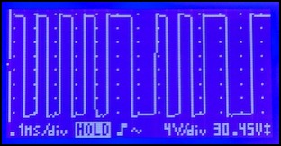
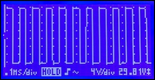
Zephyr DCC Command Station Output: Zero Throttle (left), Full Throttle (right)
Now although the meter shows 30.45V and 29.81V, implying the DCC voltage is around 14.9 to 15.2V, this is the 13.8V output of my Zephyr. The reason for the difference is those little hooks on top of the waves, which are “overshoot”; voltages slightly higher than the desired value, for a very brief time.
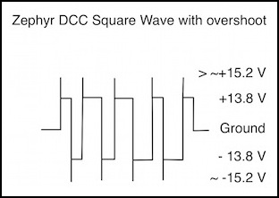
Overshoot happens because making square waves really square is hard to do. But because it’s so short, overshoot doesn’t significantly affect the average voltage, just the instantaneous peak voltage. My oscilloscope is showing maximum peak to peak voltage, but what matters to trains, and what gets shown on an RRampMeter, is the average (technically it’s the RMS Voltage, but for a square wave, that’s the same thing).
Note: if you measure a rail relative to the command station’s “ground” (assuming it has one) with a DC meter, you should get the peak voltage. That’s going to be close to the RMS voltage, but as seen in this example it will be a bit higher. This is one of the reasons owning an RRampMeter is such a good idea for anyone with a DCC layout, since it reports the DCC voltage.
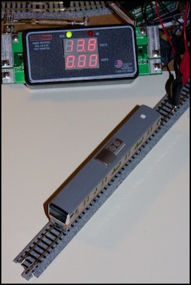
RRampMeter showing Zephyr Output of 13.8V
If you run what’s on the track through a rectifier to convert it to DC, you are essentially folding the lower half up at the midpoint (where the gap shows on the far left on those oscilloscope traces; my ‘scope doesn’t show zero very clearly). This creates a voltage that would look like a continuous line at +15V (or rather at +13.8V but with spikes to a bit above 15V), and that’s the number that’s referred to as the “DCC Voltage”. This is what comes out of a decoder, except for some loss (maybe 1 volt, per some earlier measurements I did) in the decoder electronics, which makes it the important voltage for both lights and motors. So, ideally, for N-Scale trains, we’d want that to be no more than 12 volts, and even that would be the equivalent of a power pack set on maximum throttle all of the time. But is it really 12V? No, not unless the command station has a switch to set it that way for N scale use, and most don’t.
The NMRA and DCC Voltage
So what voltage is typical on DCC? My Zephyr is 13.8V without a load, and will drop slightly when actually running trains, but it’s still significantly above 12V. By the time it gets to the track and goes through the decoder it will lose another volt or two, so what’s reaching the lights and motor may be fairly close to 12V. But that’s not the same as the command station putting out 12 volts.
While historically N-scale trains operated on a maximum of 12 volts DC, or perhaps 16 on a system designed for HO, DCC systems don’t work quite the same way. And it’s partly the NMRA’s fault for creating a one-size-fits-all definition and then making it overly broad. As I noted at the top of the page, the NMRA has defined command stations as putting out between 12 and 22 volts, meaning that ones that do are considered to conform to the rules defined in the DCC standards, and can be described by their manufacturers as “conformant” to the standards.
It’s reasonable for DCC, a product of a U.S.-centric standards-making body (although the original technology was from Lenz in Germany), to end up with one solution for both N and HO. And the NMRA does make some noises in the direction of N-scale being different; they just failed to actually state that usefully in any of their standards or RPs. And that led to some DCC systems having much higher track voltages than those of us working in N-scale would like to see on our rails, well above those typically found on DC HO systems.
Let’s recap the standards first: NMRA Standard S9 Electrical, last updated in 1984, is the master standard and applies to both DC and DCC, but it’s pretty terse, and only notes that the minimum full throttle voltage at the track should be no less than 12 volts, regardless of scale. It points to a related standard for traction equipment (trolleys or trams), S-5 Traction Power Collection, last updated in 1982, which provides for different-sized overhead wires per scale (30 AWG for N, 26 AWG for HO) when those are used to provide power, but doesn’t otherwise get into the voltage topic. The Recommended Practices aren’t much help either. RP-9, Electrical, last edited in 1973, merely says that DC packs should produce between 12 and 16 volts. It’s a nice statement of the “typical” range, but not otherwise helpful since it’s not defining any mandatory limits.
So, prior to the advent of DCC, we had a minimum voltage, and some conventions for a shared range of “typical” voltages for N and HO, but nothing more. There was recognition throughout the hobby that N was “usually” 12V and HO “usually” 16V, but that was about as far as it went, and in practice mostly it was all 16V because very little was made explicitly for N-Scale back then.
Then came DCC: Standard S-9.1, Electrical Standards for Digital Command Control, All Scales (PDF), last edited in 2004, should set limits for DCC, but the only thing it says authoritatively is that DCC command stations for N-scale or smaller can’t produce more than 22 volts at the track, and decoders have to tolerate 24V. That’s rather a bit more than 12V, or even 16V. HO and larger scales are actually limited to 27V. You have to wonder what they were thinking. S-9.1 does refer back to S9 for maximum track voltage, but since S9 doesn’t list one, that’s not helpful (bad editing job there, folks). There are several electrical RPs for DCC, but none touch on track voltage at all.
They did include some nice charts showing “typical” voltages, and those do show a difference between N and HO, but those charts also show the same 22V/24V maximum; no help there on setting limits. Those charts in S-9.1 show 12V as typical for N, and 14.5V as typical for HO (and also for S and O scales). Most manufacturers seem to design either for the 14.5V level, or provide a way to switch between 12V and higher voltages. Oddly, some use 14.25V rather than 14.5V, and claim it as an NMRA recommendation, but I haven’t found any source for that.
The NMRA also publishes conformance testing standards. The decoder test procedure just checks to make sure an N-scale decoder works at 24V. The command station procedure just checks to make sure output falls between 7 and 22 volts. Which, incidentally, means that a command station producing 22 volts is “conformant” even if designed solely for N-Scale, despite all the language about typical voltages. I wouldn’t buy one, but it’s conformant. That’s a correct test procedure given the way the standards are written. But between them, they’ve left the door wide open for trouble.
Manufacturers and DCC Command Systems
I’ve already noted that my Digitrax Zephyr puts out 13.8V. And as I mentioned above, in the real world that probably does get you close to 12V delivered from the decoder to the motor or accessories. Digitrax’s better systems have a switch to select different voltages for different scales (and an internal adjustment that lets you fine tune it). They aren’t the only company that does that. Other typical systems may be delivering something around 14V - 16V.
The manual for Lenz’s LV series of command stations and boosters notes that those default to 16V, but can be adjusted from 11 to 22V in 0.5V steps. Atlas’s current Commander puts out 14V according to them, but older versions were known to produce voltages as high as 18V. NCE’s PB series are “factory adjusted” to 14.25V (which they claim is “NMRA-recommended”). NCE’s PowerPro also defaults to 14.5V, but is adjustable over the range 9.5V to 18V.
However, I’ve seen online comments that an older Atlas system was 18V, and that Roco’s DCC system could be as high as 22V (see this link for an interesting discussion of it and a statement from the company), and that even Lenz’s Compact Starter set had a significantly higher than usual (but unspecified) voltage. Clearly not everyone was as conservative in their choice of power system, and some of those command stations are likely still out there, even if more recent designs have been corrected.
The problem over over-strength voltage may be somewhat limited, as most systems seem to be under 15V, and only a few were significantly in excess.
Adjusting Output Voltage
A command station may have a way to put out fewer volts, such as a physical switch, a software setting, or an adjustment potentiometer on the circuit board. One thing to be aware of is that the extra power has to go somewhere, and it becomes heat on the voltage regulator of the command station. Selecting a lower voltage will make the command station run hotter. The output will generally be a few volts below the input voltage from the power supply, if an external power supply is used. A manufacturer may support use of different-size power supplies, and if they do choosing one appropriate for the output voltage you select is a good idea. Consult the manufacturer to be certain.
You can also reduce voltage with resistors, but they’re going to get hot, and need to be very high-power ones, and they’ll need to be different sizes depending on the current. As an example, if a command station is putting out 5 A @ 16 V, dropping it to 12V would require only a 0.8 ohm resistor (R=V/I=(16-12)/5) inline on one of the outputs. But that resistor would be dropping 20 Watts of power, and be hot enough to be hazardous assuming it was rated for that. If the output were only 3 Amps, the resistor would only drop the voltage to 13.6V, and it would only put out a bit over 7 Watts. In short, trying to “condition” the output yourself isn’t really a very good approach.
