


DCC for Kato Japanese Trains
Kato’s newer Japanese passenger trains, most of those made since about 2005, are “DCC Friendly”, which means they can accept a drop-in decoder. For some this means that they have little hatches on the motor and cab cars. Installing the decoder for interior lighting is less easy as it attaches to a bracket on the lighting itself, so the body shell needs to be removed and the DC lightboard replaced. Kato has reportedly said that the DC lightboard (11-209 and presumably 11-211) can safely be used with DCC (you lose the ability to turn the lights off, however, if you don’t use the FR11 DCC lightboard, and the lights are quite bright since DCC means full voltage all the time).
Note that while the older bulb version of the interior lighting (sets 11-204 and 11-206) are electrically compatible, operating bulb lights on DCC voltage will produce a lot of heat and may damage the model.
Because Kato Decoders are made by Digitrax, they have some features in common, although they are not exact matches. See the Digitrax Decoders page for details about those decoders, which may shed additional light on a Kato feature.
Kato Decoders for EMU/DMU Passenger Trains
Kato sells three decoders, made by Digitrax, for use in their “DCC Friendly” passenger trains:
- EM13 (Kato 29-351), motor decoder for motorized cars (max sustained current 1 Amp, peak 1.5 Amp).
- FL12 (Kato 29-352), two-functions (up to 125 ma each) for head & tail lights in cab cars.
- FR11 (Kato 29-353), single-function (65 ma max) for interior LED lights only. (I haven’t used these)
Note: 60 mA is the current normally associated with a single 12V bulb light, although some apparently can be as high as 75mA. It’s a bit odd that the FR11 is explicitly noted as only being for the LED lighting kits, which use less than 20 mA, and yet is rated to support a 65 mA output. The restriction could be due to the heat issue noted above, but may also be a caution since many locomotives will connect multiple lights to one decoder output; Kato doesn’t appear to do that, but perhaps some models do.
English-language documentation for these is available as PDF files on Kato USA’s N Scale Accessories page. These appear to be simple translations of the Japanese instructions that come with the EM13 (at least this comes from some distributors; from others I’ve received decoders in a plastic bag, instead of the plastic box with anti-static foam, and those were not accompanied by documentation). And they don’t discuss all the features or issues of the decoders.
Note: all of these decoders are Digitrax decoders, and similar to their DN163 products but with a subset of features. Since JMRI doesn’t presently distribute a Kato definition, if you use DecoderPro you should select one of the Digitrax DN163 models (any of them). However, a few things can’t be programmed this way (and some things it lists won’t work).
Note: JMRI now has a definition on their decoders page, but it wasn’t included with the current production version of JMRI I downloaded. It appears identical to the DN163 definitions, but I haven’t compared them in detail.
According to Kato USA’s English-language documentation, all three support Digitrax Transponding, and are compatible with operation on DC track. The EM13 supports back EMF (see below) and controls related to the motor (speed tables), and the FR11 will work with both the 11-209/11-210 white LED and 11-211/11-212 LED V2 interior lighting kits (don’t use them with older bulb lighting).
The EM13 and FL12 are double-sided circuit boards, with one side designed to contact the brass pickup rails that run between the trucks of the car, and the other side having outputs for the motor or lights. The FR11 is simply a replacement for the light board used in car lighting, which has contacts on one side (which connect to the pickups through some additional brass strips, the same as the normal DC lightboard. Kato has reportedly said that the normal lightboard is safe to use on DCC, so I don’t have any experience with the FR11. The one benefit it would bring would be the ability to turn the car lights on and off. But I have nearly 100 light-capable cars at present, so the cost of a decoder in each would be prohibitive. Just adding the lighting kits is a lot of money.
Note: the EM13 is very sensitive to placement. I’ve had a non-working decoder start working after a bit of very minor prodding with a jeweler’s screwdriver, which didn’t seem to move it at all. Before trying anything more drastic, try sliding it back and forth and making sure it’s flat but not pressed too deeply into its receptacle.
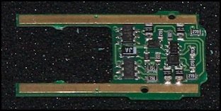
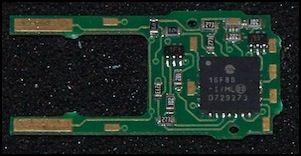
EM13 Motor Decoder, L: pickup side, R: motor side
The FL12 is reversible (front to back, not top to bottom), and should be installed in opposite directions in the head and tail car, so that one lights the headlights when the other lights the tail lights (you also need to make sure these match the direction the motor moves in, so the headlights are on the front of the train; if not, reverse the motor car or reverse both FL12’s, reversing the motor car is easier).
The FL12 has two sets of contacts on its upper side (photo on right below), one each for the taillights and headlights, and is reported to sometimes fail to make good electrical contact, i.e., fail to work, when installed. Sometimes adjusting the position can fix it. I thought I had this problem, but it turned out to be “operator error” instead.
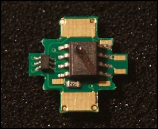
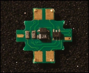
FL12 Cab Light Decoder, L: pickup side, R: light side
Note the offset and centered small brass pads on the light side of the FL12 (right photo). When the decoder is placed in the receptacle if the centered pad is visible in the large opening where the decoder was inserted, the car will display headlights when “forward” is selected on the DCC throttle. If the offset pad is visible, it will display tail lights instead. While it’s possible that some cars could have their wiring reversed, it seems likely that this is general.
My “Operator Error” the first time I installed one was in forgetting that the FL12 is a DCC decoder, and on a decoder Function 0 controls the status of lights. If F0 gets set to “off” somehow (and on my Zephyr it’s off by default for a new address), both the head and tail lights will be dark, although they’ll flash briefly when the decoder is powered up, or when it loses and regains track voltage, which can be confusing (see Equipping a Kato “DCC Ready” EMU for a more complete description). Just press F0 once the car is on the running track and a throttle has been assigned its address, and the lights should come on.
This is a useful feature, as it allows the decoder to be used to turn off the lights when two trains are consisted together. But you’d need to program the decoder to “off” on the programming track, otherwise all decoders on a train with the same address would be turned off. You need to use the same address for the motor and head/tail lights so that the head/tail lights will swap when the motor direction is changed. (actually, you could probably use function remapping to make one car’s lights respond to F3 or F5 instead of F0; I haven’t tried that).
Reading Decoder CVs
DCC as originally specified didn’t have a standard way for a DCC decoder to send messages back to the command station, which was needed for a CV’s value to be “read” by the station, so one was implemented by having the decoder vary the power it was drawing, and having the command station sense power draw variations. The only problem is that for this to work, you need a load on the decoder large enough that it can be used to create a detectable variation. Motor decoders can use the motor, which is generally sufficient. Light-only decoders will also typically work if there are bulbs connected to them. But LEDs don’t draw much power, and Kato’s surface-mount LEDs even less. This creates problems.
Kato notes that FR11 and FL12 are “write-in” only; you can’t read the settings of CVs from them. This isn’t strictly true: I’ve managed to read the FL12 on my Zephyr’s Operations Track, although not consistently (it may depend on the lights of the model too, one of my trains won’t read at all). I think the key here is having a short and well-connected link from command station to track, and clean track and wheels for a good contact. Any extra resistance in the circuit (e.g., if using part of the layout as a programming track) would likely make it harder to distinguish the subtle variations used to report CV values back.
The EM13 is also somewhat erratic in reading (sometimes it fails to read a CV on the first try, although repeated tries will usually work). And trying to read all of the CVs in one pass with JMRI always fails about halfway through for me. I’ve been told that reading in Paged Mode works much more reliably, but I’ve seen that fail as well.
I’ve been told that if you connect a 100 Ohm load across the outputs (which would be a bit tricky to do) the FR11 and FL12 can be read the same way as the EM13, but not only haven’t I tried this, I’m not likely to (the outputs aren’t easily accessible on most models, and I don’t want a permanently installed load in the car as it would prevent the lights from working properly and waste power, so what’s the point?). I might build a test jig for validating new decoders, and if I do that I’ll add a resistor and try this out.
Decoder CVs
The Kato decoders are essentially special-purpose Digitrax decoders. The FR11 is a single-function function-only decoder used to turn its built-in LED for interior lights on and off. The FL12 is a very simple headlight/taillight decoder. The EM13 is a motor-only (no functions) decoder. The default values listed here are from an EM13 decoder with a CV7 version ID of 51.
Addressing
All three decoders (well I haven’t tested the FR11 but the documentation says so) support four-digit addressing, although it apparently needs to be set manually, rather than by using a command station’s “set address” function. I’m not clear on why, but one comment suggested the order in which things were set mattered, and the set address function did it wrong and left the decoder in a confused state where it needed to be reset. See below for how to set these four-digit (extended) addresses.
The EM13 also supports consist addressing (it’s irrelevant for the FR11), however while you can write a consist address into the FL12, it does not affect its operation, which makes consisting with them rather useless since the head and tail-lights won’t change with direction changes sent to the consist address.
CVs used: (most apply only to EM13)
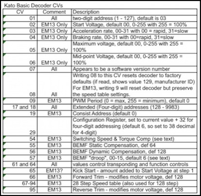
WARNING: My test decoder had problems shortly after I programmed CV54, and the default for that wasn’t what it was documented to be. Although it’s listed here (and in fact the “switching speed” part of it actually works) I’d advise against changing it at present. I’m going to do some more investigation.
Note: CV29 is the Configuration Register, which is used as described on this Digitrax page (and see below).
JMRI Note: JMRI lists several CVs for the EM13 that do not appear in other documentation I’ve found. Most of the new entries do not appear to work on my FL12 or EM13. The also fail to list others that do work. It appears that the Kato decoders listed in JMRI’s programmers use this list, and as such aren’t valid. Use with caution.
Kato’s documentation lists the following CVs: 1, 2, 3, 4, 5, 6, 8, 17, 18, 29, and 57. The FR11 and FL12 documentation additionally discussed CV61 & 64 (see below). It also notes CV8 as having the default value 129 (meaning it’s a Digitrax-made decoder) and being able to set it to a value of 8 (Digitrax’s standard “reset” code). The reset is confirmed, see below.
I’ve confirmed that CV08=129, which is Digitrax’s ID. While Kato has an assigned DCC manufacturer number (40), they don’t appear to use it for these.
The version number on the one I checked (CV07) was 51, but JMRI lists the range of 49 to 51, suggesting that there has been more than one version of this decoder or software. I think this is actually the Digitrax software version, as I’ve seen 51 on some DN-series decoders as well.
Decoder Reset
These decoders support the standard Digitrax reset function. Set CV8 to value 8 (decimal) to reset the decoder to factory defaults. Doing this will not erase the User ID CVs (CV105/106).
There is a second Digitrax reset supported on the EM13 (and some of their other decoders, although it’s not well documented). Set CV08 to 9 (decimal) and it will reset the decoder to factory defaults except for the speed table settings (CV29 is reset, to use of the table is turned off, but the table itself is preserved).
CV29 Values
Kato’s documentation sheet lists the possible values of CV 29 as:
6 = 28/128 speed steps, Analog Conversion, Forward direction, 2 digit address
7 = 28/128 speed steps, Analog Conversion, Reverse direction, 2 digit address
38 = 28/128 speed steps, Analog Conversion, Forward direction, 4 digit address
39 = 28/128 speed steps, Analog Conversion, Reverse direction, 4 digit address
But this list is followed by an “etc.”, suggesting that other values may be acceptable.
Note: the meanings are from other Digitrax documentation.
CV54 Values
I don’t advise adjusting this at present, as I’m unsure if a failed decoder may have been related to changing it.
The default for this CV on my decoder was 64, which doesn’t match the documented values.
0 = switching speed and torque compensation off
add 1 = enable F6 control of switching speed
add 16 = disable torque compensation
I’ve confirmed switching speed works. Set CV54 to 1 (or 17) and F6 will modify several factors such as accelleration and braking to allow more direct control of the locomotive while switching.
CV55/56/57 Values
Kato’s BEMF seems to be a fairly standard implementation of the Digitrax BEMF. This has reasonable default settings and is on by default.
CV55: Static Compensation, default 128 (0 is off, 255 is max)
CV56: Dynamic Compensation, default 80 (0 is off, 255 is max)
CV57: BEMF “droop” (intensity), default 6 (0 is off, 15 is max)
Note: CV57 can be set differently to alter BEMF in consist mode. A value of 1-15 multiplied by 16 and added to the basic value sets the value used when in a consist (thus to set both to 6, set it to 6*16+6 or 102). I haven’t seen any documentation that this works on the EM13, and I haven’t yet tested it myself.
See the Back-EMF page for more info on BEMF in general and on Digitrax’s implementation.
CV61 / CV62 / CV64 values
These three decoders appear to be a Kato-specific set of configurations that replace the usual Digitrax methods of doing the same thing. CV61 and CV64 for the FR11 and FL12 are documented by Kato. Use of CV62 is not, nor is use of CV61 for setting EM13 transponding. The information on the EM13 and CV62 is unconfirmed by me at present except where noted, and came from a JMRI page.
Kato’s documentation omits mention of CV64 for the EM13, implying that it does not apply, and thus there is no way to disable Transponding. This may merely be an oversight because there is no function output (i.e., 00 / 00 may disable Transponding and 02/00 enable it). I’ve seen third-party information that says there are several EM13 functions that can be controlled via CV61 and CV62 (not CV64), and they include transponding, but I haven’t verified that.
Functions are listed individually for FR11 and FL12, as FL12 does not support all settings. By default, F0 controls the head/tail lights, and F1 controls interior lighting.
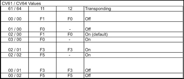
Another way to state this is that CV61 can be set by adding the following values:
- 1 = remap function (varies by decoder)
- 2 = enable transponding
the remap function will disable F0 control on the FL12, and reset the FR11 to use F0 instead of F1.
and CV64 means
- 1 = set function to F3 (unless CV61 remap used)
- 2 = set function to F5 (unless CV61 remap used)
EM13 Configuration:
For the EM13, add values from the following list to get a decimal number, and program that into CV61 or CV62 (set to zero otherwise).
CV61: (default is 32, enable basic speed table in 128-step mode)
-- enable transponding (add 2 to enable)
-- support for AC “split field” motors (add 4 to enable)
-- use F5 to disable speed compensation (add 16 to enable)
-- use basic speed table in 128-step mode (add 32 to enable)
-- short-circuit protection (add 64 to disable, but you’d be crazy to do so)
CV62: (this doesn’t appear to work for the FL12, and doesn’t apply to the EM13)
- add values 1-127 to set the FX rate adjust
- add values 128-255 to set the lamp voltage (only for bulbs, set to 0 for LEDs)
Note that the numbers for CV62 regard function outputs, and thus would apply to the FR11 and FL12, but not the EM13. In any case, they don’t seem to work.
CV65/66/95 Values
These are adjuncts to the speed table. It’s not clear if they work only with the 28-step table or also with the Vstart/Vmid/Vhigh table (I haven’t tested that yet).
CV65: Kick Start, default 2 - the value added to the first speed table setting immediately on transition from stop to moving.
CV66: Forward Trim, default 128
CV95: Reverse Trim, default 128
Forward and Reverse trim work on the EM13 with the 28-CV table in 128-step mode (I haven’t tested kick start yet). At 128 this do not modify the motor voltage. Values above 128 are a multiplier (increase speed when moving in that direction), values below 128 are a divider. For example, to have the train run half as fast in reverse at the same throttle setting, set Reverse Trim to 64 (a 0.5 multiplier to speed in reverse).
Programming 4-digit Addresses
Kato’s decoders can use Extended Addressing (4-digit addresses), but they can’t be set using the method normally used by control systems, at least not with most command stations. There’s something about this that apparently confuses the decoder. Instead, you have to do it manually by setting three CVs. You must use the programming track to set the address.
Note: using JMRI, I can set Extended Addressing by entering the four digit address (in the Advanced Programmer panel). However this probably works because it’s doing the same three individual writes that I’d do manually, and retrying if there is a write failure.
Make sure the decoder and train work correctly with the default settings (and address 03) before attempting to set extended addressing. If they do, and setting the extended address fails to work, you can reset the decoder to factory defaults and try again, knowing that you made a mistake, rather than being unclear if the problem is the decoder or your configuration of it.
Note: use normal (CV01, 2-digit) addressing for addresses from 1 to 127, and extended (CV17 & 18, 4-digit) addressing for 128 and above.
First, translate the 4-digit address you want to binary or hexadecimal and split it into two 8-bit quantities. The easiest way to do this is with a DCC calculator, but you could also do it with a scientific calculator that converts from decimal to hex or binary. Put the low byte in CV18. Then add 192 (decimal) to the high byte and put it in CV17 (the linked calculator does that extra addition for you).
Actually, you can do the conversion just by dividing by 256 if your control station allows programming using decimal numbers. For example, 1250 (decimal) divided by 256 is 4.8828125. This means the high byte should be 4 (plus 192 as above), and the low byte should be 0.8828125 times 256, or 226. So, setting CV17 to 196 and CV18 to 226 gives the decoder the extended address of 1250. But you can’t use it until you enable extended addressing, which is the next step.
Finally, read the value of CV29. This will probably have a value of 6 (although it could be something else). Add 32 to whatever it is and write the result (i.e., 38 if it was 6) back into CV29 to enable use of extended addressing. This same method will work for the FR11 and FL12, but you usually can’t read CV29, so you’ll have to assume it was 6 to begin with.
Now move the car to the track, and try running it with the new address. If it doesn’t work, you probably set the address wrong. If it still works on the old address, you forgot to set CV29.
Note: remember that if you mess up the decoder, you can reset it to the default values by writing a value of 8 into CV8. That’s the standard Digitrax “reset to factory default” sequence. Do that on the programming track, preferably, as you’ll end up with the whole train set to address 3, and you might have another train on the layout with that address, which could be confusing.
Decoders for Kato Locomotives
Material regarding decoders other than the Kato-branded ones discussed above has been moved to a separate Lightboard-Replacement Decoders page.
