


Train Detection
Detecting the presence or absence of a train, or its identity, is an important capability. It can be used to trigger crossing gates, to manage lineside signals, to create a dispatchers panel showing where trains are, as part of an automation system, or for all of these purposes.
Train detection is also intimately connected to the concept of a layout Control Bus, as detecting something isn’t much use if you don’t tell anyone. Actually, that’s not quite true, as a detector could simply be wired to a crossing gate to turn it on (dropping the gates) while a train was nearby, or to a signal, to make it red when a train was on the facing track. But that’s a bit simplistic, so in most cases, if you’re going to bother with detection, you probably want something a bit more sophisticated in terms of communications.
There are a number of methods for detecting trains (for a more detailed overview of the types, see this page). The most sophisticated is to have the train announce its presence. DCC decoders that support RailComm can do this, but it requires devices along the line that receive and recognize this information. A more basic approach is simply to detect the fact that the train makes an electrical connection between the rails, allowing a current to flow.
To do this, the track must be divided into electrical blocks, and a sensor attached to each block. This sensor will then report the presence (and if RailComm is in use the identity) of the train in its block. A simpler method is to place a detector beside the track that will report when a train passes. These can be simple photocells, or tiny switches touched by the wheels of a passing train. But one problem is that these can only detect a moving train at one point, whereas a current-based detector will detect even a parked train (on DCC layouts) anywhere in the block.
This page will focus on block-based electrical detection of trains. You can also detect trains with other methods, like photocells or IR photodiodes. I’ve done the latter using an Arduino for one of my layouts, and it’s written up on my Arduino IR Sensors page. But while that method works, it’s not going to be as good as current detection at detecting a parked train. For things like hidden storage tracks, I’d want current detection.
Electrical Block Detection
In a model railroad that uses the track to deliver power to the trains the rails will have a voltage difference, and when something that conducts electricity is placed across them, a current will flow. That something may be a motor pulling hundreds of milliamperes (mA), or a resistor drawing less than 10 mA, many detectors work for currents as low as 1 mA.
Current in a conductor (wire) can be detected by measuring the voltage drop it creates across a resistance, or by measuring it indirectly by the current it induces in another wire. The latter is usually more expensive, but somewhat safer (since the measuring wire isn’t connected to the track, there’s no way track power can get into the sensitive electronics). Systems that use voltage drops are often described as “diode-based” since they use diodes to divert a portion of the current (and going through the diode to get to the track causes the drop in track voltage). There are two common methods of indirect measurement: the simple induction coil (also called a Current Transformer) and the more sensitive Hall Effect sensor.
Most inexpensive detectors are of the voltage-drop form, often but not always using an optoisolator to separate the track wiring from the rest of the detector, for a degree of protection. The big problem with voltage-drop systems is that they have to discard a significant amount of the track power in a resistor to make a measurement. Some can consume as much power as a small N-Scale locomotive. Typically they’ll also typically reduce track voltage by 0.7 volts. Current-sense transformers are more efficient, as the amount of power lost in an active detector is much lower, and there’s no voltage drop.
Block Occupancy Detection and Reporting
To use a current-based detector, the track feeder for one rail (not both) in a block of track that’s insulated at both ends is fed through the hole in the decoder. If the block is fed at multiple locations, the sensor should be applied to the feeder before it splits, so that power drawn anywhere in the block will go through the detector, otherwise operation may be erratic.
Note: the diagram below shows both rails insulated, but this will work with common-rail DCC systems also. Only the red rail needs to be cut and insulated for the detectors to work.
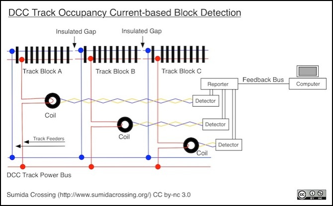
The track feeder may have to be taken to the detector, or the detector may use a coil that can be located on the feeder a moderate distance from the detector. The detector itself just provides a simple yes/no output, which could be used to directly control something like a crossing gate. A typical single detector costs around US$10 - US$20, but they’re often sold as boards containing several detectors. These do not include the circuitry needed to interface directly with a computer.
While standalone detectors can be useful, a more preferable method today is to pass this information to a computer, which can display the location of trains on a track diagram, and control things based on which detectors are in use. To do this, the detector will need to connect to something that can report the status back to the computer over some kind of control bus (often just a serial link). Examples of such a devices are: motherboards for C/MRI, Digitrax DS64 accessory decoders for Loconet, the Railstars Io for NMRAnet, the Train Brain for CTI systems and the Lenz LR-101 for XpressNet.
Often the detector and reporting device are on the same circuit board, but not always. And while there might be one detector with one reporting device, it’s more efficient (and quite common) to have a single reporting device report the status of several detectors (on the same circuit board, or on separate boards wired to the reporting device.
Using Detectors
To use a current-sensing detector, there must be current. A locomotive motor is going to draw at least 30 mA even with a very efficient modern N-scale loco running “light” (pulling no cars) on level track. That’s quite a lot and easy to detect. Car lighting can also be detected, although as tiny surface-mount LEDs have come into use, current for these may be 7 - 10 mA, and much harder to detect, but still reasonable.
To sense single cars that aren’t lighted (e.g., freight cars in hidden storage), you would need to put tiny surface-mount resistors on wheelsets. There are a number of ways to do this, but the simplest is probably to use conductive epoxy (as described here and on Wiring for DCC). A 10KOhm surface-mount resistor will create a current as low as 1 mA depending on track voltage, so either you need more than one in a block, or a very sensitive detector. You could use smaller resistors, but then you’ll lose more power in every axle, which will add up quickly (a 1 KOhm resistor will use 10 - 15 mA of current, so ten cars would use as much power as the small loco pulling them, and they’d use it even if you parked them on a siding). Most people seem to use 10KOhm resistors, with some using 15K or even 22K and counting on multiple cars to be in a block for detection, but other use resistors as small as 4.7K.
Note: on a 15V DCC system, 10KOhms produces 1.5mA. Most layouts have track voltages a couple of volts lower than the supply, and N-scale supplies may be 12V DCC. I’m assuming 10V DCC track current as the lower limit (officially DCC works down to 7 V DCC), which produces 1 mA of current through a 10KOhm resistor.
Another problem is that a simple detector may only work on current flowing in one direction. That’s no problem for a locomotive or resistor, as they draw power from the DCC source in both directions. A simple LED circuit, however, could draw power from only one direction, and if it’s the opposite to that used in the detector, the LED circuit can’t be detected. LED lighting with a “full wave rectifier” will draw power from both directions, but this is an area where some lighting circuits economize.
Very sensitive detectors used with DCC can have a problem with falsely detecting empty tracks as occupied. This is caused by capacitance between the rails drawing a very small amount of current on each DCC cycle (two conductors, the rails, separated by an insulator, the air, make a capacitor and can store charge, although only a tiny amount). The normal solution is to desentitize the detector (not all allow for this), which does mean that it can’t detect very small currents, like a single resistor-equipped wheelset. Another approach is to keep the length of track blocks used as detection sections fairly short, since that reduces the amount of capacitance, and hence the current on empty rails.
Another potential problem lies in accessory decoders that draw power from the track, like turnout controllers. These draw power continuously, so any block containing one will always be detected as occupied. Accessory decoders that use track power either need to connect directly to the track bus, or draw power from a section of track that isn’t sensed (often you’d isolate a switch from the sensed blocks on either side anyway, so a switch with a built-in accessory decoder would be easy to isolate).
Feeders can pick up “induced” current from adjacent feeders or track bus wiring. It’s best to “twist” a “left rail”/“right rail” pair of feeder wires around each other if they run for any distance, and to avoid running them parallel to other feeders or to bus wires. If you have to cross other DCC wires, try to do it at right angles. Also, if feeders are long, it’s best to sense them as close to the track as is practical, as this minimizes false current cause by capacitance in the wiring (you can’t entirely eliminate this, and the detector has to compensate for it, but designing to minimize it is good practice). The more sensitive a detector is, the more likely it is to detect false currents, since these will be small.
Typical Block Detection Sensors
Here is a list of the commercially available current-based sensors I’ve found. Some of these only work with the manufacturers specific system, although I’ve omitted ones that include additional circuitry for such systems, so there’s the possibility that these could be adapted for other systems without being too expensive. For some helpful comments on the use of these sensors, see Alan Gartner’s Wiring for DCC site’s Block Detection page.
Circuitron BD-2 (US$25 list)
This is a simple voltage-drop sensor, which can work with DC or simple DCC use. The normal version is limited to 3A systems, but there is also a BD-2HD for use with up to 6 Amp systems (such as most larger DCC command stations and boosters). Because it is a voltage-drop sensor, it reduces track voltage by about 0.7 volts. When a train is detected, the output is connected to ground, otherwise it is an open circuit. This can be used with most types of logic boards with the addition of a pull-up resistor connected to the logic board’s internal positive voltage (on an Arduino, use INPUT_PULLUP mode). The BD-2 requires a 10-18 Volt AC or DC power supply. The BD-2 has a rather unique approach to installation, placing it in line with feeders to an isolated section of the common rail. This allows detection sections (on layouts wired as common rail) to be independent of electrical blocks). Sensitivity is adjustable, and reportedly as low as 0.3 mA (50K ohms on a normal layout).
Circuitron BD-3 (US$20 on one site, but does not appear to be available)
The BD-3 is fully isolated and designed only for DCC use. It includes a position to add a connector compatible with the C/MRI detector motherboard. It requires a 10-18 Volt power supply. This appears to be new, and as of October 2013 not yet available. Although listed in their catalog (edition 301) there is no specification sheet for it on their website, and no hobby stores appeared to have them in stock. From the catalog description, it appears to have similar specifications to the BD-2 except for being fully isolated, only working with DCC, and having a place to solder on a C/MRI-compatible connector.
CTI TB002-DCC (US$20)
The TB002-DCC is a coil-based pair of detectors on a single board. It’s designed for use with their Train Brain control bus system (power supply comes from the Train Brain, and that’s also where the sensitivity control is located), and it’s unclear what it’s detection specifications are, or if it can be used independently. However their manual suggests that these are designed for a +5V pullup resistor supply and this implies that one could be read with an analog pin on a microcontroller. They also make a conventional diode-based detector pair for DC layouts, for the same price.
Dallee TRAK-RT (US$30)
This is a coil-based sensor for one block that controls a relay. It can be used with DC or DCC. The relay could be used to directly control a device, or connected to a on/off sensor on a control bus module of some kind. It requires a regulated 12V power supply.
Digitrax BD-4 (US$30)
This is a coil-based sensor for four blocks. Although they don’t actually say so, this would appear to be for DCC use only. No detection level is listed, but it claims to detect wheel resistors (of unspecified size; an older version of the documentation apparently recommended 10 KOhm resistors). They warn against using this with “supersonic” decoders. Apparently there is some problem with noise sensitivity that can cause false detection, but it only occurs with some command stations and works fine with supersonic decoders on others (see this Yahoo thread); they reportedly fixed it in the BDL-168 (which includes the Loconet circuitry, so it’s not listed here), but not in later editions of the BD-4. This is the least-expensive sensor, if you need four of them per location.
Lenz LB-101 (US$24)
The LB-101 contains two independent current-sensing detectors for use with DCC only. Each of these will close an “electronic switch” when a train is detected, and the detector can sense currents down to 1 mA. The LB-101 apparently uses track power to power itself.
NCE BD-20 (US$15 list, but often available for less, particularly in bulk)
This is a coil-based sensor for one block, designed for DCC use. The output is designed for logic boards, and pulled “high” to +5V when no train is detected, and “low” to ground when one is. It is sensitive enough to detect a current of 8 mA or less (a newer document suggests 3 mA, see note), suitable for SMD LED car lighting and larger or multiple on-wheel resistors. It can be used with a variety of reporting systems (including with NMRAnet). There were apparently two versions of this, although the current version replaced the previous one c. 2002. The original, designated “BD-20” (“Rev. B” on a schematic from NCE) can be recognized by the use of a two-position screw-terminal connector. The present “BD-20A” (“Rev. C” on a schematic from NCE) has a four-position screw-terminal connector. It’s usually just referred to as a “BD-20” (or “BD20”) without the “A”.
Note: detection sensitivity on the BD-20 is apparently around 10-12 mA with the wire fed through the coil. Looping the wire multiple times can increase the sensitivity (see the schematics in the linked page above describing the two versions). With four loops (the maximum safe number on a 5A command station), sensitivity is around 2.5 to 3 mA.
RR-CitKits BOD-1 (US$13 list)
This is a coil-based sensor with screw-terminal connectors. It is diode based but can be used with either DC or DCC. It uses a current-loop approach, or one pair of pins is connected when the sensor is occupied (a second pair connected only when the sensor is empty is used). It is intended for use with some kind of input device (such as a DS-54) or some circuit (like a crossing gate).
RR-CitKits BOD-8 (US$38 list, plus US$15 for a set of 8 detection coils; also requires use of a Tower-series controller)
Despite the name similarity, this is very different from the BOD-1. It uses coil sensors (8 of them), and is designed to be used in conjunction with their “Tower” series of input devices, including both the TC-64 (original and Mark II versions), TowerMan and Tower-LCC. The original serial TowerMan controller (which is LocoNet compatible) has been joined (as of early 2016) by the LCC-based Tower-LCC, making this the first block detector available for LCC. Note that this uses all 8 sensors on a Tower ribbon cable, so a maximum of two (16 detectors) can be used with a TowerMan or Tower-LCC. Still, that works out to US$11 per detector (including Tower-LCC and coils).
Do-it-Yourself Block Detection
Block detection of trains actually isn’t that hard, electrically. As noted above, there are two main techniques used: voltage-drop sensing, and induced-current sensing. The former is what most systems used in the past, and many still do today. Done right, it works quite well, but there are a lot of ways to do it wrong. Current sensing is how some of the more sophisticated solutions work, particularly for DCC.
Voltage-drop systems are required for DC layouts (and will work with DCC if designed for it). But problematically, these put the track voltage on the same circuitry as is connected to some more sensitive electronics, like a computer. The best of these use optical isolators (“optoisolators”) to protect the computer. Many cheaper designs omit this, which I think is a really foolish bit of cost-savings. Model Railroading with DCC has a circuit diagram for a good detector with isolation, which costs under $7 each if you’re building more than 10 of them.
Current sensors only work with DCC (or AC-powered layouts), since DC doesn’t have the same effect of inducing a current (although the Dallee detector above seems to be similar and works with DC; at least in theory you could detect the change in current when a train enters or leaves a block and there are complex circuits that will detect DC current). The current controls what is effectively an amplifier circuit, so the small induced current acts as a switch to control other circuits, usually switching them between “on” and “off” states. This circuit could be a high-current circuit to control a light or relay, or a logic circuit to switch between “one” (+5V) and “zero” (ground) states, depending on the circuit design.
There’s a nice description of how this works along with a sample circuit on this site. These are simpler circuits than voltage-drop designs, but the coils aren’t cheap (US$4 - 7) so the end cost is probably about the same, but could be less. One nice touch of these is that the coil isolates the track power from the computer, and the coil can be mounted remotely from the circuitry (with some care: use twisted-pair wires run away from DCC lines and of limited length), so one circuit board could easily support multiple block detectors spread over a section of layout.
Another circuit for this is available from this site, and the author also sells circuit boards.
Another page describing examples of both kinds of detectors is this one.
