


DCC Decoder Testing and Troubleshooting
There is nothing quite as annoying as going to all the work to install a DCC decoder, only to have it fail to work. And unfortunately, Kato’s decoders frequently don’t work when installed. Why? Mostly because they’re sensitive to positioning, and make poor electrical contact. You could, of course, have a bad one, or have fried it with static electricity. But assuming you handled it with reasonable care, it’s probably an installation problem.
There’s some basic troubleshooting you can do. While this is pretty much universal for any decoder, I’m going to focus on the decoders Kato sells (mainly for their Japanese-prototype trains), as these have a few quirks of their own. A decoder tester is a very helpful tool to have, as it removes the train from the possible set of problem causes, and lets you focus on the decoder itself.
This page is about testing decoders before installation to see if they work. For comparative testing I did to selected decoders for my trains, see the Decoder Comparison Tests page.
DCC Decoder Tester
There are commercial testers for this (see the photo of the ESU 51900 Tester below), but since all these really are is a way to connect the decoder to the necessary output devices (motor and lights) you could make your own fairly easily. In fact, for Kato’s specialized decoders, you’d need to do that anyway, as they only function when placed against the appropriate contact strips. After having problems with several EM13 motor decoders, and being unsure if the problem was the decoder or my installation, I built just such a tester for it.
First the basics: a tester takes the place of the train. Thus you need to connect the output of the DCC Command Station to it (usually via a pair of “rail” contacts), connect the decoder to it either through one of the standard sockets, or by wiring it up (the DZ123 below has its wires plugged into the contact strip on the ESU tester). The ESU tester is particularly nice as it has a motor on it, but it’s an HO-sized motor, and I was worried that this might have too high a stall current for the EM13.

DZ123 Decoder on ESU tester (right) with RRampMeter (left)
So I built a simple socket out of styrene and brass strips, and wired the right side (track) to the DCC command station through the RRampMeter so I could see input voltage and power draw. Then I connected the output (motor) side to a length of track via the yellow and black alligator clips. The DE10 locomotive on the track acts as the “motor”. If the decoder works, it will send DC to the output (the track) and the locomotive will move. This worked quite well, and let me discover that most of my EM13’s worked fine, but one apparently had a burned-out motor circuit as it wouldn’t move the locomotive at all (I suspect I blew it playing with the ESU tester, but it might have been defective to begin with).
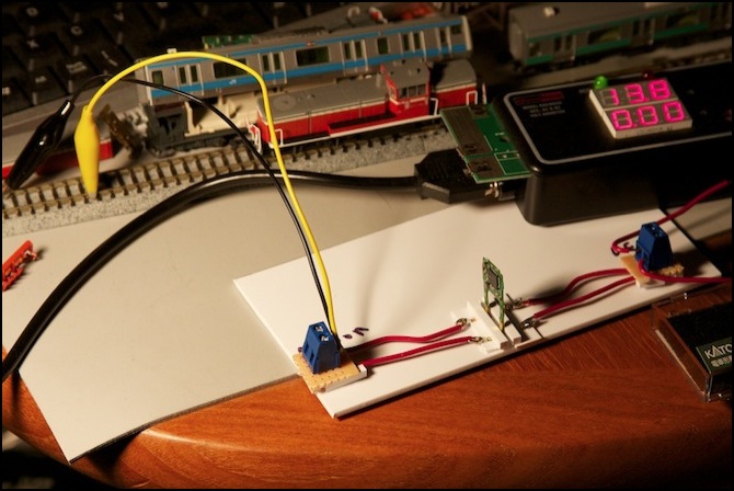
EM13 Motor Decoder on simple test rig
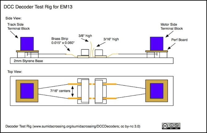
And here’s a more detailed explanation of the construction. It’s mostly just held together by plastic cement, although I used Liquid Nails to glue the perfboard down to styrene blocks. The brass strips were bent to shape with small needle-nose pliers, and then had wire soldered to them. When the decoder is removed the track-power strips contact the motor strips, which shouldn’t be a problem for the test locomotive as long as it’s not left that way for an extended period, but I usually disconnect the track power from the rig when changing out the decoder anyway (there’s an alligator clip out of the sight to the right in the photo above).
I connected short wires with alligator clips to both terminal blocks. The “track power” ones can be moved between my DCC Command Station’s Rail outputs (i.e., the RRampMeter outputs) and the programming track outputs, so I can program the decoder then “move it” to the track for testing by moving the two clips.
Troubleshooting
There are some basic things you can do to check out the decoder. You can do these with the decoder in the train and the train on the track, or you can do it using the decoder in a specialized decoder tester. You will need a DCC command station that can read and write Configuration Variables (CVs, see your manual), and a computer that connects to the command station, running DCC software like JMRI, is very handy, but not essential.
Step 0: Did you run the train on DC first? If you didn’t you can still try step 1, but if that doesn’t work pull the decoder and try DC. Maybe the train itself isn’t working. If you have a decoder tester you should still confirm the train works on DC before doing the install, but you can test the decoder independent of that.
Another “is it plugged in” thing to check is whether the track you’re testing on is connected, and the DCC station working. If you have another DCC train you can run, see if it works. You’d be surprised how often the obvious is the problem. And the obvious includes loose wires, tripped circuit breakers on the command station, and even command stations that have been put in standby and aren’t powering the rails (some command stations have switches for this, and I’ve been burned this way more than once).
Yet another “step 0” test is to tell the controller to take control of some other ID, then tell it to take control of this one. That will ensure you have active control (some command stations “forget” decoders they’ve been told to control after a relatively short time; Digitrax calls this “purging”, and it can be turned off, although you may not want to do that).
Step 1: Can you read it? (This only works for the EM13, not reliably for the FL12 or FR11) Put the train on the programming track and try reading CV 8, if you get “129” (decimal) or 81 (hexadecimal), which is the manufacturer ID for Digitrax, then it’s readable. You can do this test for any brand of decoder, although the number you get back will be different, obviously, but it will always be non-zero.
Note: you can’t read the FL12 or FR11 because reading a CV requires a load on the decoder, and the load provided by the LEDs they drive is insufficient. I’ve actually managed to read the FL12 sometimes, but it’s erratic.
If you can’t read an EM13, the most likely problem is poor electrical contact. Take the locomotive apart, check the placement of the decoder (make sure it’s not upside down, see the Kato Decoder page, and that the alignment tabs are in the right place) and try again. With the EM13, it’s important not to press it too far towards the motor; if it’s bending the piece of plastic between the motor and the flywheel, it’s too far in. Moving the decoder around just a little can sometimes help. With the FL12, it should be all the way into the socket, but if that doesn’t work, back it out a hair (no more than a millimeter). Some of my decoders had small bumps of circuit board on the end away from the motor, which interfered with the fitting into the slot; I found I could trim most of these off with some sharp flush-cutting sprue cutters, although you have to be carful not to damage the board.
You can also clean the exposed parts of the brass rails and or the decoder contacts with a clean pencil eraser, but don’t rub too hard; you just want to polish it, not remove the thin layer of metal. A microfiber cloth dampened in rubbing alcohol (not full-strength isopropyl, but the thinned-down stuff by preference) could also be used for cleaning, particularly in the more inaccessible spaces, but let it all evaporate before doing any more work. But unless the model is old, or the decoder was left out on a workbench, dirt isn’t likely to be the problem.
If that doesn’t work, for the EM13 try a thin shim (of a non-conductor, like styrene or index card) under the brass rails, which will press the decoder more firmly against both the rails and the motor, but not too thick a shim, or that will cause problems itself by bending the decoder away from the motor contacts.
If all else fails, try another decoder or try using this one in another train. If it works in another train, the decoder may be failing to make good contact with the brass pickup rails (see the shim suggestion above).
Step 2: If you can read it, the first thing to do when it’s not working is reset it. Write 8 into CV8, which will reset all the CVs to factory defaults (including setting the address back to 3). Make sure you can read it (using address 3, see step 1) afterwards, and then see if it runs. This can be done for any decoder made by Digitrax (including these Kato decoders); other manufacturers have other methods to do a reset.
If you can read it, and reset it, and the train worked on DC, but it still won’t run on DCC, it may be making poor electrical contact with the motor tabs even though it’s making good contact with the pickup rails. Too thick a shim can cause this (as could the lack of one). Cleaning the motor tabs may also be a good idea (but hard to do since you need to clean the underside; microfiber cloth, which won’t leave threads behind, and rubbing alcohol, are the keys to that).
If all else fails, it may really be a defective decoder. As it’s made for Kato, don’t expect the usual Digitrax warranty to apply, and there’s nothing to indicate that Kato provides a warranty, although you might be able to get the seller or your regional Kato office (Kato USA for those in the U.S.) to do something.
Other Problems
If a decoder doesn’t work in a train, it may be the train. While a train that works on DC should run fine once equipped with a decoder, DCC is not DC, and that can cause problems.
DCC is a alternating-current (AC) waveform, but unlike ordinary household AC, which is a simple stream of evenly-sized and spaced sine waves at a frequency of 60 Hz (or 50 Hz in some parts of the world), DCC is a stream of different duration square waves, with a typical frequency in the kilohertz (kHz) range. AC doesn’t act just like DC.
First, the loco could have electronic components in the wiring that interfere with the DCC signal. The most common of these is a capacitor connected across the motor (often attached to the motor, but it could be elsewhere). This filters AC out of the signal reaching the motor (or emitted from the motor). But DCC is AC, and filtering it is counter-productive. Also, the output from the decoder to the motor is PWM, which is also a variable square wave, and also usually in the kHz range. And while a capacitor on the motor might not be a big problem, it’s also a potential source of them. Removing capacitors is almost certainly a good idea.
Locomotives often have circuit boards that control the headlights. These need to be isolated from the tracks and driven off outputs from the decoder (see the Lightboards page). Depending on how you do this, you might have left part of the board connected, and it could have circuitry on it, or connections to things, that aren’t obvious. Try removing the lightboard if possible, to see if that clears up the problem. Even the board itself can be a culprit: see this site for a story of how a homemade board had unexpected effects due to capacitance from the acid-based flux used to solder the NEM socket.
