


Planning the Foam Scenery
Above the wooden table structure, layers of polystyrene insulation foam were laid to raise “ground level” above the river, and to provide room for the “underground” subway. The idea was that the subway will be above the first layer of foam, to raise it slightly above the river where it crosses, and the surface will be far enough above that to provide clearance for the subway tunnel. The foam I’m using comes in 0.75” and 2” sizes, (they also had 1.5”, but I didn’t use that), in 2’ x 8’ strips.
Note: my scenic materials are in English dimensions, while the prototype measurements are largely given in metric. I’m going to give the prototype numbers here in both, but I’ll stick with English for the actual dimensions of the table and foam. Also, note that “N-scale” here refers to Japanese N, or 1:150 scale.
Looking at photos, I’d guessed the high part of the Sumida’s banks to be no more than 30 feet (9 meters) above the water, with trains at most an additional 20 or so feet higher when running on above street-level track. Land around the Kanda river (the one by Ochanomizu station) is even lower, with track height perhaps 20 feet (1.6 inches in N scale) above the water.
But this appears to have been an overestimate. The “super levees” on the lower Sumida river are built to withstand a storm surge of +5.1 meters above low tide (tides run about 2 meters at non-surge maximum). However, the land behind them is lower, in some places a meter below high tide level. To achieve that level of protection, the embankments were built to a height of +6.4 - +6.9 m along the Sumida. Thus, a bridge would need to be at least 7 meters (23 feet, or 1.8 inches in N-scale) above the low tide mark to clear the embankment. It’s clear that road bridges are this high or higher, and rail bridges (typically elevated above the roads) are higher still. Nonetheless, it will have to be higher than the actual one to make the subway work, and it’s not going to look right if I make it too high.
This is one of those times in model-building where you have to build something that has the appearance of the real thing, without actually replicating it. That’s fairly common, but not necessarily easy to plan. One way to approach it is to mock up what you’ll eventually build, so you can try out different arrangements or proportions and see which “look” right.
I set up a couple of bridges with some foam against my backdrop to see how they looked at different heights:
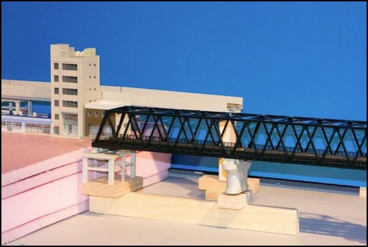
This shows the truss bridge at the original “ground” level of 4.25” (53 scale feet, or 16m). This arrangement allows 2.75” for the subway tunnel plus a solid cap of foam. Visually, the elevated bridge may be too high above the river at 6.5” (81 feet, 25 meters). This was my original design, but after this mock-up, I decided to do something with fewer layers.
Note: this also shows the original dark-blue backdrop, before it was repainted to a lighter color.
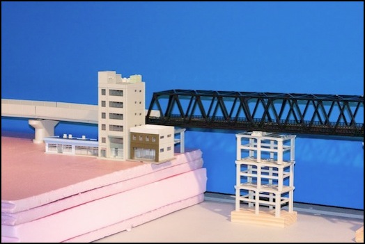
Here’s a different view, putting the truss bridge at the elevated (6.5”, 81’, 25m) height. It’s very clear that it’s just too high. I’m going to need to bring things down a bit to get it closer to the way I want it to appear.
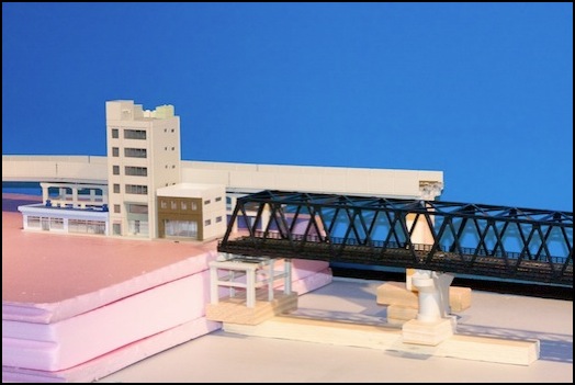
This is the middle ground, with the ground level bridge at 3.5” (44 scale feet, or 13m), and the viaduct at 5.75” (72 scale feet, or 22 m). The ground level bridge looks okay, although it does feel a bit high (and at 44 scale feet it is about 50% higher than the prototype). If I couldn’t make a 2-inch tunnel with a thin (sheet plastic) cap work for the subway, I was going to go with this method.
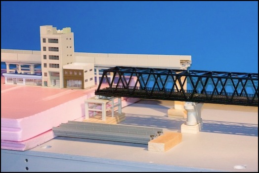
This is the lowest possible arrangement, with double-track elevated viaduct at 5” (62.5 scale feet, or 19 meters), the truss bridge at “ground” level of 2.75” (34’, 10.5m), and some single-track viaduct sections at subway level of 0.75” (9’, 2.9m). The “ground level” bridge looks okay (compare with the Toei bridge on the River Scenery page), but the elevated viaduct still seems out of scale.
This arrangement of foam layers allows 2” for the subway tunnel, which is about that allowed for track crossing under a viaduct without a bridge (i.e., about 1 5/8”, or 41mm, once you take roadbed and track height into account). Although I thought this might be too little, some quick measurements convinced me that the subway line would fit, given a few assumptions about what I’d run in it. And so, after much thought and these tests, I settled on the use of two layers of foam, a 3/4” base layer and a 2” upper layer, as my standard terrain. Foam would be cut away where necessary to provides slopes or rivers, and other scenery would be built above this in places, but both the Riverside Station scene and the River Crossing scene would use this basic design (the Urban Station had only the 3/4” layer, so the “subway” would be at ground level in that scene.
Note: I later discovered that not all 2” foam is actually two inches thick, and had to make some fixes to get sufficient clearance in the subway tunnel.
