


Catenary on Japanese Railroads
Catenary is the general term used for the overhead wire used to feed electricity to trains. In Japan such wire is used for Shinkansen, commuter, and even subway trains. There are many different forms of catenary wiring used in Japan, but essentially it is a roughly-level wire that is touched by an electrical contact on the train, and above it one or more suspension wires that hang from poles in a slight curve. Between the two are periodic vertical wires or brackets that maintain their spacing.
A distinction is made in more formal usage between simple “trolley wire” single-wire systems and “catenary” which uses one or more additional wires to support the current-carrying wire, although “catenary” is often used informally to refer to both types. Even more formally, this wiring is known as Overhead Line Equipment (OLE) in technical papers about Japanese rail. The term Overhead Contact System (OCS) is also used, although according to Wikipedia such use is primarily European.
Providing Power to Trains
The “catenary” term is generically used to refer to the whole system of power distribution along the railway and into the train itself, although the word has a more precise meaning. There are several components to the system: power transmission over long distances, transfer of power from the long-distance system to the “catenary”, and transfer from the catenary to the train itself. We’ll cover these, starting at the train’s contact. On the train, the power may go direct to the motor (though some kind of simple voltage control system) for low-voltage DC, or may need to be converted from a higher voltage (typically AC) to the voltage used by the motor. Newer technologies also allow the choice of AC or DC motors to be made independent of the power supply (historically motors were DC on DC supplies, and AC on AC supplies, although there was some use of DC motors on AC supplies).
Trolley Poles, Pantographs and Shoes
A train is a moving object, and getting the power from a stationary supply into it involves some kind of electrical pickup rubbing along a stationary conductor. There are several ways to do this, involving both overhead conductors (usually suspended wires) or ground-level conductors (usually some kind of solid metal rail). A return path for the electricity also needs to exist, and usually this will be in the rails on which the train rides, treated as a “neutral” or grounded circuit element and periodically bonded to a return wire to minimize resistance. The same vehicle can be made to run on more than one kind of power supply structure, and this is common where previously separate lines have been combined over time.
Note: the return path can also be via a second overhead contact wire, but this is very rare.
The trolley pole is one of the earliest power pickup methods, and has largely been replaced today except on historical equipment (some of which is still in day-to-day use). This is used with an overhead wire (and can be used with both trolley wire and catenary structures, which we’ll get to further down the page). A trolley pole is attached to the vehicle in a way that allows it to pivot both up and down and from side to side, and it is raised up to the wire with springs. An insulated rope is often attached to the top of the pole, allowing the operator to pull it away from the wire and tie it down out of the way. This is also used to put the pickup back on the wire when it comes off, which does happen. At the very top of the pole is a wheel, shaped like a pulley with a U-channel structure, which rolls along the wire. The wheel is conductive, and either the trolley pole, or more likely a wire attached to it, is also conductive. Trolley poles are only, as far as I know, used with low-voltage DC supplies (e.g., systems using less than 1,000 volts DC in the wire) although it’s possible some are used with European 1,500 VDC and 3,000 VDC systems.
The pantograph is the newer method for collecting power from overhead wires. This is a structure which can be raised and lowered, but not moved side-to-side. At the top is a horizontal bar, or bars, the upper surface of which contacts the wire and collects power. Pantographs are held up with springs (or perhaps other systems in newer designs) and can be lowered (often this is motorized). Pantographs are common today on all systems.
An overhead line can also be a rigid conductor (essentially a suspended rail above the train). These are used in tunnels where clearances are tight, and are limited (in Japanese practice anyway) to 90 kph, although the reasons may have more to do with subway construction than limitations of the rail method itself. An ordinary pantograph is used with such systems, and the overhead rail may be connected to ordinary catenary wiring where clearances are more generous.
Finally, when power is supplied at ground level, a “shoe” will be used. This is a flat metal plate, hinged where it attaches to the vehicle, that rubs along either the top or underside of a rail mounted alongside the tracks (the “third rail”). Third-rail systems are typically limited to low-voltage DC power, both due to the size of the required air-gaps for high voltage, and for safety reasons. Third-rail systems are limited to top speeds of about 100 kph, although the Tōkyō subways apparently limit its use to 70 kph.
It is also possible to place the power supply underground between the two running rails, which is essentially another kind of third rail system. This approach is sometimes used in urban centers where overhead wires would be unsightly or otherwise problematic. In these kinds of system, the conductor will be offset to the side, so it would be unlikely for anything inserted into the slot in the ground (like an animal’s foot) to contact it.
A train will often have more than one pickup (this is particularly common with third-rail equipment, since the third rail has to have gaps at switches). At low speeds more than one of these can be in use, and this is typical of Japanese commuter trains, which have motors on several cars, but not all cars in the train, which are associated with individual pantographs serving one or two cars. At higher speeds, there are issues with multiple pantographs contacting the wire, and it is typical for only one to be raised, and for wiring within the train to distribute power from any pantograph to all motors.
Overhead Wires
The word “catenary” comes from the latin word catena, meaning “chain”, which is used to describe the mathematical curve of a flexible wire suspended between two fixed endpoints. Since the wire carrying current needs to remain in contact with the collection device attached to the train, a varying height is obviously a problem, particularly as speeds increase and spring-loaded contact devices cannot keep up with rapid height changes. Support structures evolved to hold the power-feed wire at a constant height, and the most common of these uses a second wire in the shape of a catenary curve with varying-length “dropper” wires attached to the trolley wire to hold it level (some more complex systems use more than one supporting wire). In this method, the contact wire must be under tension, often several thousands of pounds of tension, to keep it level, which is achieved by placing weights on one or both ends.
Trolleys (or Trams, to use the word more common in international English usage) operate at low speeds, and many use a simplified form of overhead line with a single wire, often called the “trolley wire”. Although pantographs and similar mechanisms may be used with either, many older Trolleys use a “trolley pole”. Trolley wire and poles work well at low speeds, and have the benefit of being relatively simple to install and maintain.
As speeds increase a single trolley wire and poles are inadequate, and more complex wiring (i.e., catenary) and pantographs are required. Some systems that operate at lower speeds may use catenary anyway, as it can permit longer spans between support poles, and thus lower construction costs. And pantographs have largely displaced trolley poles even on low-speed trams lines (mainly for reliability reasons).
Note: the contact wire is sometimes called the “trolley wire”, even when it is part of a catenary structure.
As an aside, it is important not to confuse multi-wire trolley wire systems that have two contact wires in parallel with catenary, which has two or more wires arranged vertically with only one contact wire. Multi-wire trolley systems are used where the rails cannot be used as a return path for electricity, e.g., on electric busses or where ground conditions would cause corrosion due to leakage currents.
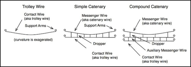
In catenary wiring, the contact wire carries the electrical current that is picked up by the train. The messenger wire or some other wire serves as a supply (the “feeder wire”) for this current. Both the messenger and the contact wires are “energized” (carry electricity at the same voltage), even if the messenger is not counted on to act as a feeder. The feeder, whatever wire it is, is typically a larger diameter wire than the contact wire, and often of a purer copper composition (contact wires are alloys designed to reduce wear and increase strength), and so more suitable for distance transmission of power than the relatively small contact wire. In AC systems there may be equipment between the feeder and contact wire to convert voltages. I haven’t found any indication that DC systems do this, and the typical DC feeder is at the same voltage as the contact wire.
In simple catenary, the contact wire is suspended from the catenary wire (aka messenger wire) by droppers, which vary in length so that the catenary wire may follow the curve of a wire not under tension, and the contact wire (which is under tension) may be horizontal. In compound catenary, the connection between the auxiliary messenger wire and the contact wire, which are both under tension, is always of the same length, and is sometimes referred to as a “hanger”, however the terms “dropper” and “hanger” seem to be used interchangeably depending on author.
In newer Japanese systems the auxiliary wire may be directly connected to the contact wire (by means of “ears”, whatever they are). This allows the stronger auxiliary wire to bear the tension of the contact wire is heated by current or otherwise compromised, which reduces the potential for broken wires.
Some English-language Japanese papers seem to use “contact wire” as an abstract to refer to both the contact and a directly-bonded feeder wire, separate from a non-bonded feeder connected through a transformer (see the description of AT systems further down the page). However details of the physical wiring of this are unclear. Normal usage in other sources is that the feeder is the long-distance wire bonded to the contact wire.
Even “simple” catenary isn’t necessarily so simple. Urban Japanese commuter systems are increasingly using a system where the messenger wire is the electrical feeder, and where an auxiliary wire (not an auxiliary messenger) called a “feeder messenger” wire runs just above the contact wire (50 mm, or 2” above it) to reduce strain on the contact wire. Or at least, that’s what one paper says. I haven’t seen a photo showing this in use yet.
As seen in the photo below, the Yamanote line uses a system with a dual messenger wire (at least in some places) above a single contact wire, which is still “simple” catenary since there is just one level of supporting wire. This can appear to be a single messenger wire from a distance, particularly when viewed from the side.
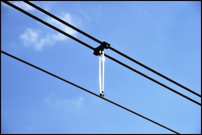
Yamanote Line catenary with double-messenger and dropper, Harajuku Station, Tōkyō (2008)
Photographer: ykanazawa1999
This distribution system (feeders and contact wire) is fed from power substations at regular intervals. With DC (direct current) power, these must be closer together than for AC (alternating current) power, which is one reason long-distance trains such as the Shinkansen typically use AC systems.
Catenary needs to be supported by poles at regular intervals. A typical spacing is 50m, but this can vary (in particular it will be closer on curves, to keep the wire more centered over the track).
The same supporting structures that carry the catenary will also typically carry wiring from the substations (feeder wires), and may additionally carry the medium-voltage or high-voltage feeds to the substations. On narrow-gauge systems, feeders and contact wires carry “low voltage” (1500V DC) power. For Shinkansen, the feeders carry 25,000 volt AC power, as do the contact wire, and will thus have larger/longer insulators and greater spacing between wires and other objects. The use of 22,000 volt distribution lines along DC-powered railway lines to feed individual transformers along the line is also typical (per Japanese WIkipedia).
There are additional photos on the Catenary Images and Electrical Images pages.
Catenary and Electricity
While “catenary” refers specifically to the wire that carries power to the roof-mounted power pick-ups (pantographs) on trains, the term is also generally applied to the other wires and the supporting structure. In addition to the trolley (aka “contact”) and messenger wires, there are also wires that distribute power along the line (called “feeder wires”). The reason for this is that catenary wire has relatively high resistance, and so frequent attachments to some wire more suitable for power transmission are needed. In some cases, this is handled by the “messenger wire” as noted above, in others separate wires atop the poles supporting the catenary are used. In at least one paper on the Japanese railway, this collection of wires is called the “feeding system”.
In addition, the supply line is provided by power from a substation, and this is used to divide the catenary up into electrical sections (or blocks). All trains within a section are drawing power through the same substation (there may be more than one electrical section connected to a substation by separate feeder wires). There is a practical limit to the size of wires (and of transformers at the substations) and so in urban areas with more trains, substations need to be spaced more closely than in suburban or rural areas with less traffic. On commuter lines around Tōkyō, transformer buildings seem to be spaced about every 2 km and can be spotted via Google Earth by looking for complex structures above the tracks, where wires to/from the transformer are supported.
Trains may use AC or DC power (as described on the Propulsion page) and be fed from catenary carrying either AC or DC. AC catenary can have substations further apart, and this is more economic for long-distance lines. All Shinkansen lines use AC power on the catenary. But for historical reasons, Japan makes quite a bit of use of DC catenary, even on long-distance “main line” routes. Because DC requires more complex electronics to change voltages, DC catenary is typically at the voltage used by the motor: between 600 Volts and 1,500 Volts, while AC catenary is typically at much higher voltages (20,000 Volts or 25,000 Volts are typical in Japan). In terms of catenary details, the higher-voltage AC lines require larger spacing between the catenary wire and other metal structures to prevent arcing during wet weather, and larger and more complex insulators.
AC Catenary Wires (JR West Shinkansen, Hiroshima, Ōsaka, 2009)
Photographer: dugspr
Much of the information below on power transmission and distribution comes from a paper on Railway Electric Power Feeding Systems describing Japanese practice, although this was supplemented by other sources (see the references section).
Transmission Wiring
To get power to the contact wire from distant power plants, a transmission system with very high voltage AC is used. This is because transformers can be used with AC to raise the voltage (and thus lower the current and resistive loss that’s related to current).
Note: apparently some non-Japanese utilities are now using high-voltage DC transmission lines with solid-state DC-DC converters in place of transformers. I haven’t found any mention of this approach being used in Japan.
The high-voltage AC is likely reduced before being passed to the railway, since long-distance transmission systems can use very high voltages indeed, often several hundred thousand volts. The railway then operates its own transmission system paralleling the tracks to provide power to periodic substations. JR East also operates its own power plants (using at least one distant hydroelectric facility) and associated long-distance transmission systems.
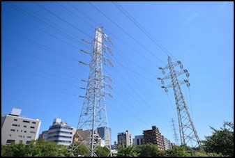
Utility Transmission Lines in Shin-Yokohama (2011) - per the photographer, the right tower belongs to JR East
Photographer: ykanazawa1999
Substations
Even urban power transmission uses fairly high voltages (up to 100 kV or more), so there need to be substations where the power is stepped down to the voltage used along the line. With AC systems there may even be two stages of this, with substations stepping down to an intermediate voltage, and then additional transformers (perhaps pole-mounted along the tracks) stepping down to line voltage. I’m not aware of any Japanese DC system using such transformers, but that’s apparently done in other countries so it is possible that there are some.
In Japan, the narrow-gauge railways (both commuter and intercity) typically use 1,500 V DC on the contact wire, but some use 20,000 V (20 kV) AC, while the Shinkansen uses 25 kV AC. There are some other systems using 750 V DC or 600 V DC. Although 3,000 V DC systems are common in some parts of Europe, they are not used in Japan.
In metropolitan areas where space is at a premium, a substation will typically be a two-story windowless structure connected to both high-voltage transmission lines and trackside wiring. In more rural areas, fenced enclosures with equipment on concrete pads are likely more common, although I haven’t found specific examples of these (people don’t often photograph substations of any kind, so examples online are rare). Note that a railway substation is a separate facility from the electric utility substation, which converts very high voltage AC to the voltages typically used around a city. The railway substation typically takes this lower (but still quite high) AC and converts it to track voltage.
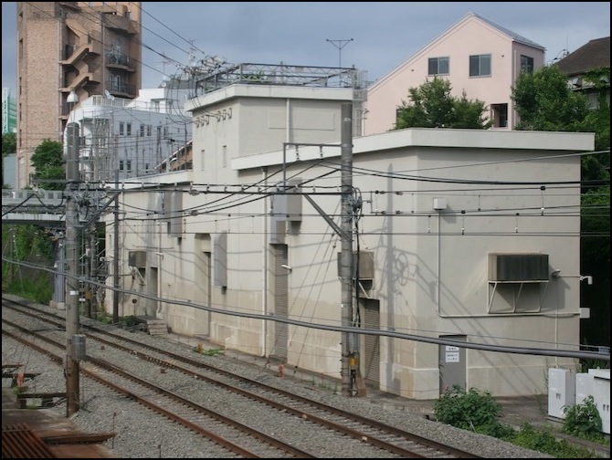
Substation on the Tokyu-Toyoko Line (2007)
Photographer: Grant “gmat” Matsuoka (Copyright, used by permission)
The following substation is fairly interesting: it is actually located on a platform above the tracks just west of Kugayama station on the Keiō Inokashira Line. The tracks are in a cutting, so the platform is at street level, making effective use of space, as well as being easy to access for maintenance.

Keiō Inokashira Line Substation (Suginami, Tōkyō, 2007) - converts AC to 1500 V DC
Photographer: おむこさん志望
A typical Shinkansen substation looks much like a utility substation: a large fenced area with gravel, containing concrete pads on which are mounted transformers the size of a small van, and various supporting poles and other systems (e.g., circuit breakers). I haven’t found a specific example, however the following picture of the Tōkyō Electric Power Company (TEPCO) substation at Tama is an example of a large utility substation that converts long-distance transmission voltage to one usable by the railroad. In this specific case, the photographer identifies the station (in a caption for another photo) as converting 275 kV to 66 kV.
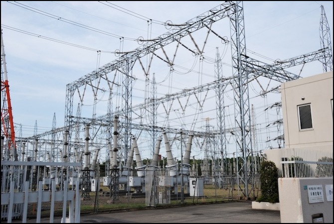
TEPCO Tama Substation (Kodaira, Tōkyō, 2010)
Photographer: ykanazawa1999
Feeder Wiring
While the messenger wire is better at carrying electricity than the contact wire, it still has a limited capacity and can suffer from high loss over distance, particularly in DC systems. Additional wiring (“feeder wires”) may exist along the tracks to carry power to periodic attachments to messenger wires. And the messenger wire and contact wire may be broken up into arbitrary sections by insulated gaps, to limit the amount of current in one section, or to enable independent maintenance or other activities affecting a portion of the catenary.
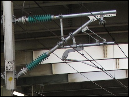
The photo below shows the trolley and messenger wire (lower right, and center bottom), various wires used to maintain position, plus a connection leading up from the horizontal supply wire under the superstructure. The three wires at top, right, are probably DC supply lines (“feeder wires”) from transformers along the line, given the relatively small insulators. See the right-hand “support structure” photo further down the page for an example that has both these and what is obviously a higher-voltage pole-top line, which is probably AC to the transformers.
DC Catenary Wires (JR West, Ōsaka, 2007)
Photographer: Hyougushi
Boosters and Auto-Transformers
For DC systems, transmission voltages of 22, 66 or 77 kV AC are converted to 1,200 V AC by transformer, and then 1,500 V DC by a rectifier. This is done at a “substation” located along the line. There could be an additional stage of long-distance transmission at higher voltages, stepped down to the ones listed above at a substation near to the line. The AC narrow gauge lines use voltages of 66 kV, 77 kV, 110 kV, and 154 kV AC, converted to 20 kV AC using a transformer. In general, these are done very simply, with the transformer driving the feeder wire through a circuit breaker, and no other systems.
However, the modern DC system uses solid-state electronics to perform the AC to DC conversion. Both the transformer and rectifier are located at substations, with these spaced every 5 km in metropolitan areas, and 10 km in more rural ones. However close examination of lines around Tōkyō show spacing as close as 2 km on heavily-traveled lines.
This may be changing. Regenerative braking systems can’t feed power back through such systems, so unless there are other trains drawing power in the same section of track, the returned power would be lost. Newer technologies (such as are already used on the train vehicles themselves) for DC-DC conversion of voltage may be used in the future to allow return power to be fed back into the larger system. These would use AC stepped down to 6.6 kV AC by a distribution transformer, and then a transformer with a “regenerative inverter” to convert this AC to 1,500 V DC for use. Sources are unclear as to the location and size of this new equipment, but it is likely the transformer and inverter would re-use existing substation facilities to avoid additional construction of wiring.
Some narrow-gauge systems use Booster Transformers (called “BT” systems). These allow the substations to be spaced every 30 to 50 km, but with voltage further stepped down to track voltage via periodic “boosting transformers” placed between the contact wire and the feeder wire. An advantage of these over simple single-transformer systems is less electrical noise inducted in adjacent wiring, particularly in communications wires used for signals and other systems that typically operate at (and are insulated for) low voltages, where induced currents could damage systems or provide a safety hazard.
Note: The text of the article clearly discusses BT systems in terms of non-Shinkansen lines, but the equipment described, and the diagram in the article, would appear to limit its use to AC systems (such as the few AC narrow-gauge intercity lines) since it’s connecting a transformer directly to the contact wire. Exactly where the BT is located (pole, lineside pad, or substation) is not clear. While a similar system is could potentially be used on inter-city DC lines where distances are long, replacing the BT with a solid-state DC-DC converter, the article doesn’t mention this.
Another method, the Auto Transformer (or “AT”) system is also used on narrow-gauge (likely also only AC narrow-gauge) lines. This allows 44 kV line voltage to be stepped down to 22 kV on the contact wire (it would appear that 44 kV is fed along the line in feeders). Part of the function of the auto transformer appears to be to get return current off of the rails, reducing loss to leakage into the ground. The benefit of the AT system is that the full substations with larger step-down transformers can be spaced further apart, every 90 to 110 km. AT wiring also induces less noise in adjacent communications wiring. However, AT transformers are not small, and effectively require a small substation facility themselves (at least in the one photo I’ve seen; it’s possible smaller ones are used on narrow-gauge lines due to their lower power requirements relative to the Shinkansen lines).
Shinkansen lines use voltages of 77 kV, 154 kV, 220 kV and 275 kV AC, converted to 25 kV AC for use. The typical structure of this is to take three-phase AC and convert it to two-phase AC at line voltage using a transformer, and then feed one phase to the overhead for each of the two railway lines (Shinkansen lines are always paired). Note: a different paper notes that voltages down to 66 kV have been used as three-phase input to the two-phase transformer, but this is likely an older system.
Shinkansen also use AT systems. A photo in the Railway Feeder Systems paper shows a lineside AT transformer on a concrete pad in a fenced substation. This would appear to be too large for pole mounting. A Shinkansen AT system uses 60 kV AC, and allows substations to be spaced every 20 to 60 km. In these, the auto-transformers are placed every 10-15 km and the substations every 20 to 60 km. The Tōkaidō Shinkansen was converted from BT to AT in 1991 and it would appear no Shinkansen presently use BT systems.
Note: in several articles on Shinkansen AT systems, it would appear from diagrams that two feeds run to each line from the substation (in one these are confusingly called “contact wire” and “feeder”) and the AT transformer is placed between these and the rail. One of these is also bonded to the contact wire (or is the contact wire). I’ve seen one photo which might show two supply wires associated with each track, separate from the messenger and contact wire, but this was ambiguous. A diagram in the Delhi paper cited below shows the feeder being pole-suspended off to one side, and a messenger wire directly above the trolley wire (aka contact wire) in an AT system. The messenger wire may thus be the bonded feeder referred to as the “contact wire” in Japanese papers (it certainly appears to be in this planned Indian system derived from Japanese practice). However, another section of the Delhi paper discussing grounding shows two pole-mounted feeders (one identified as “feeder négatif”, suggesting it’s from a French system and not reflective of their design).
An alternative design for Shinkansen, called the coaxial feeding system, uses 30 kV AC and places the substations every 10 km. In this, the power is distributed through a coaxial cable with the outer (neutral) portion connected to the return rail and the inner to the contact wire. This has the advantage of having very small space requirements and creating less interference in adjacent communications lines. There do not appear to be any lineside equipment, just the substation. This is likely used in metropolitan areas where more trains are drawing power for acceleration in a shorter length of track; the article specifically mentions that the Tōhoku and Tōkaidō Shinkansen lines use it in Tōkyō.
Note: there are several mentions of 30 kV feeders and of 60 kV being “twice” the line voltage. An RTRI paper on feeder transformers notes that 25 kV is the “nominal” output voltage of the transformer, while 30 kV is taken from the transformer specifications for the output. This would appear to be two different ways to say the same thing.
Catenary Structure and Supports
Very little information about Japanese catenary is available online, and essentially none about wire height or support structures. From models, it can be approximated that the height of the contact wire is about 18’ above the track. For comparison, contact wire height on Amtraks’s Northeast Corridor is reportedly around 23 feet above the rail. North American trolley wires were originally strung at a height of about 18 feet, although they would be higher (at least 21 feet) at places where Trolley lines crossed steam lines.
A comment on the Japanese wikipedia page for Overhead Lines (架空電車線方式) says that the minimum height is 4.7 meters (15’ 5”) except in tunnels or confined spaces, per a comment translated by qwertyaardvark on the JNS Forum. The Power Feeding Systems paper noted above says catenary is “about 5 meters” above the track and a height of 5.08m is noted in the Delhi paper.
Measuring some N-scale models of EMU trains (all Kato) provided a maximum height above rail for the top of a fully-extended pantograph of 35 - 37 mm, which at 1:150 scale equates to 5.25 - 5.55 meters (or 17’ 3” - 18’ 3”). However, measuring my one model of a Shinkansen (Kato Series 500) provided a maximum pantograph height of only 30 mm, which at 1:160 scale equates to 4.8 meters, or 15’ 9”, which, although it seems quite low, is apparently a reasonable height (see Japanese N-scale for a refresher on why the two are different scales).
Catenary wire is supported by structures, often called “poles” although they are usually more complicated. Older construction used fairly complex truss structures, assembled from individual straight or angle bars. This was (and is) labor-intensive to build and maintain. Even Shinkansen lines seem to have been built using such structures. Most modern systems use straight concrete poles with a metal cross-bar attached to the poles with brackets, or curved metal poles. The best source for information on these is photographs of the particular line, as the type of structure can vary even on the same line.
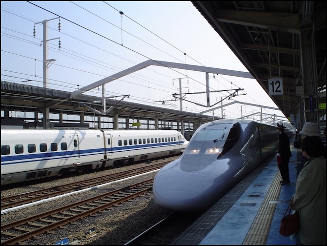
Sanyō Shinkansen at Himeji Station (2005)
Photographer: Aleksander Dragnes
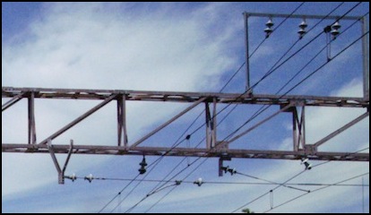
Support structures: Girder (L) and Concrete Pole (R)
Photographers: L: 海爾渥 / Hairworm, R: 4563_pic
The catenary is suspended from these structures using a variety of braces intended to maintain the position and tension in the wire, and to electrically isolate it from the support structure. For lower-speed use, simple vertical posts with insulators can be used to suspend the messenger wire (which in turn suspends the contact wire). On Shinkansen (and possibly high-speed narrow gauge) lines, more complex hardware is used to directly suspend both the messenger and the contact wires.
An additional feature is that some poles are equipped with systems to maintain the tension in the catenary, to keep it as flat as possible. This is particularly important at higher speeds. The more common style is known as a “gravity tension balancer” (重力式, “gravity”, plus the phonetic テンションバランサー, or “tenshonbaransa”) or “wheel-type tensioning device”, and this style is appropriate for both Shinkansen and narrow-gauge trains. The other style is the spring tensioner, which normally wouldn’t be appropriate for a Shinkansen, however an improved version that can be used on Shinkansen lines was recently developed (see paper below). The Japanese wikipedia page noted above has a brief mention of hydraulic dampers, which appear outwardly similar to the spring tensioners; these may be used on low-speed lines where damping vibration is desired, and tension is less of an issue.
Tensioners aren’t common, typically being located 1 km to 1.6 km apart, so more than a couple of them on a typical model railroad would not be prototypical.


Catenary tensioners: Weight (L) and Spring (R), both (2008)
Photographer (both): Tennen-Gas
References
Some of the information provided here came from the Wikipedia articles linked above, while other details were compiled from print and web sources. Among these were:
When I was partway through researching this in 2010, a thread began on the JNS Forum that provided considerable information from Japanese-language sources.
Catenary and Trolleywire posting on The Overhead Wire blog, September 2009. (This has some good photographs).
Development of Feeder Messenger Catenary with Auxiliary Wire, Kentaro Nishi and Takahiro Hamada, Railway Technical Research Institute Quarterly, Vol. 46, #2, June 2005. (PDF version) Note: this paper has some useful information about narrow-gauge (as opposed to Shinkansen) catenary.
Development of Method for Improving Overhead Line Equipment for Implementation of Stable Current Collection at High Speed, Kunio Ikeda, JR East Technical Review #8, Summer 2006.
Development of a New Spring Type Tensioning Device for Shinkansen, Hiroshi Tsukagoshi and Nobuyuki Hirota, JR East Technical Review #2, Summer 2003
Electric Railway Handbook, by Albert Sutton Richey and William Charles Greenough, 1910 (found on Google Books, see page 590 for height information related to trolley wires)
A very useful Japanese-language website showing “various overhead poles”, which I was pointed to by bill937ca on the JNS Forum thread noted above.
Railway Electric Power Feeding Systems (PDF), by Yasu Oura, Yoshifumi Mochinaga and Hiroki Nagasawa, Japan Railway and Transport Review, issue 16, June 1998.
Practical Application of a new Feeding Transformer for AC Electric Railway Substations, by Hiroaki Morimoto, Tetsuo Uzuka, Takashi Yamamoto, and Takemi Akita, RTRI Quarterly Report, vol. 51, no. 4, Nov. 2010.
Delhi Metro Rail Corporation Pre-Feasibility Report, chapter 8 Power Supply and Overhead Catenary System, 2011 (PDF). This document describes the Japanese Shinkansen power systems in some detail, as a similar system is being proposed. Mostly this confirms material in other sources, although a couple of distances were taken from it.
Note: I haven’t been able to get google to cough up a simple link to this paper or the website it’s on yet.
