


Decoder Comparison Testing
Some of my decoders were obvious choices. Kato’s “DCC Friendly” models are designed to work with specific decoders made for Kato by Digitrax, and I just used those. Locomotives with lightboard replacement decoders have a few more choices, but for the most part I went with Digitrax models recommended by Kato. I don’t have many locomotives anyway, so if I change my mind later I’m not out a lot in time or money.
But my EMU fleet is quite large, and before I invested a lot of money in decoders, I wanted to decide what features were important to me, and how different manufacturers implemented those features. I’ve described the specific decoders of interest on my Wired DCC Decoders page, so here I’m just going to talk about the general approach I took to testing and what results I found. As noted on the other page, this testing was specific to my needs, and not intended as a general test or review of the decoders. As usual I’m just jotting down my notes on what I did, so I’ll remember and in case they’re useful to others.
At this time testing is ongoing and this page is a work in progress.
Testing Bipolar Lightboard Decoders
For cab cars, I want to use a “bipolar” decoder. This is a decoder whose function output (one needed) can switch polarity the same way the motor control does. This allows an existing lightboard that wires to the track on DC to wire to the outputs without alteration. You could use any motor decoder with a programmable speed table as a bipolar light decoder; simply set every CV in the table to the same value (255 to start) and the output will be full voltage as long as the throttle is non-zero. This has two problems: first, the light goes out when the train stops, which isn’t very prototypical, and second you can’t control the light (no way to turn it off with F0, or apply effects to it (well, not quite true, some decoders have a switching-speed function that might allow dimming). But a decoder designed for bipolar lighting is preferable.
In terms of the actual testing done, testing a bipolar decoder is much the same as testing a function output for a headlight on a normal multi-function decoder. The difference is that front and rear headlights don’t typically exist on these cars, just the headlight, and that “headlight” becomes a taillight when polarity changes, rather than simply going out.
Lightboard Test Rig
To test this, I came up with a dummy lightboard circuit and put it on a small solderless breadboard (similar to a Radio Shack 276-003, although if you’re buying one I’d suggest getting the kit with connecting wires, part 276-097).
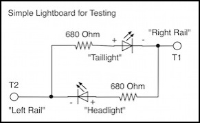
This is a simple lightboard circuit that lights the headlight LED when T1 is positive, and the taillight LED when T2 is positive. This matches normal DC practice, where the headlight would light when the right rail was positive, indicating forward motion of the train. In DCC, the blue common wire is positive and the function “outputs” (white and yellow) are negative. But in a bipolar output, my presumption is that the manufacturer is trying to replicate a DC environment. If it turns out I’m wrong, I’ll need to swap wires in the final install, but that’s not a big problem.
The choice of resistor size isn’t arbitrary. A range of possible resistors could be used, from about 470 Ohms (safe at 15V for most LEDs) to 1 kOhm (safe at the 24V maximum for N-scale DCC systems noted in NMRA S9.1, Electrical Standards for DCC (PDF)). But 680 ohms is a typical size found in some of my Japanese trains, and is preferable for smaller LEDs compared to 470 Ohms. Smaller resistors also make the LEDs brighter at lower voltages, which is irrelevant on DCC but very important in the DC environment these circuits were designed for.
And this raises one important question for testing: can the decoder be read with a 680 Ohm (or 470 Ohm) resistor on the ligthboard? Reading a CV depends on sensing variations in the load created by the decoder, and the usual mechanism for that is to cut the F0 output in and out of the circuit. With a ~18mA function load on a typical 14V system using a 680 Ohm resistor, sensing the change in load can be very hard for the command station to do.
For testing decoders with this circuit, in addition to the command station I also connected my oscilloscope and my multimeter, the latter acting as an ammeter to measure current. The purpose of the oscilloscope was both to measure the decoder output voltage, and to see the waveform, as I expected that voltage to be PWM rather than simple DC.
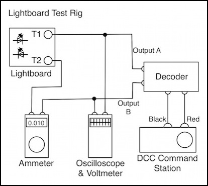
Not shown here, I also had my RRampMeter hooked up to the DCC Command Station’s output, just to be sure it was putting out the proper rail current (about 13.7V DCC from my Zephyr) and I had a computer connected to the command station so I could use JMRI for programming the decoders. To actually program the decoders, I’d swing the red/black leads from the command station’s “track” outputs to its “programming” outputs.
Testing Process
The first thing I do with a new decoder is hook it up to the programming track with a sufficient load on the outputs. For lightboard decoders, I would first try it with just the lightboard, but in many cases the resistor in the lighting wasn’t enough. For motor decoders I simply used the track and locomotive connected to the motor outputs.
Where the lightboard didn’t work for reading CVs, I instead used a dummy load for the decoders so that I could read them back. This isn’t something you could use in a train, obviously, but on the workbench where I could switch from “lightboard” to dummy load by moving a couple of alligator clips, it was very handy. The NMRA DCC standards (RP-9.2.3) note that acknowledgement by a decoder requires switching a 60 mA load in and out of the circuit. This probably dates from a time when train lights used bulbs, that had at least a 60 mA rating. And a 60 mA change in load is also big and easy to separate our from routine variations in load from an operating decoder (it’s about 1/4 the maximum load allowed on a normal service track).
The lightboards I’m working with draw less than 20 mA, sometimes much less. This means I can’t read those decoders on the service track unless the decoder manufacturers include a resistor on the board to use instead of the attached lights. But the power dissipation requirements for one are quite high, 840 mW on my Zephyr and up to 1,440 mW on a maximum-voltage track, which makes it hard to do), so that’s not at all common.
My solution was a simple circuit with 250 Ohms of resistance (and nothing else), which creates a load a bit under 60 mA, but “close enough”. I chose this value because I had a bunch of 1 kOhm resistors handy, and four in parallel gave me 250 Ohms and plenty of power dissipation. Ideally I would have used a 1 Watt, 215 Ohm resistor, but I didn’t happen to have one of those.
With the decoder connected to the programming track, I read CVs using JMRI. I try to read a whole “pane” of values at once using the advanced programmer, but if that’s problematic I’ll fall back to using the Single CV programmer and just read them one at a time. I may not read every CV, but I’ll read the ones that are important to me and note the values down. Then I’ll do a factory reset to defaults, and see if they changed. This can catch that I’m testing a used decoder that was returned, which wouldn’t be a good example of the class of decoders. It can also indicate a manufacturing problem (poor quality control). Either way, I’ll switch to another copy of that model decoder if I can, to see if the problem repeats. After resetting to factory defaults (and noting what those are) I’ll do basic testing before doing any programming.
Since I’m using a Zephyr, I can also have JMRI monitor the LocoNet traffic, which will give me some more detail on what the command station is doing and what responses it’s seeing, beyond the simple “OK” that shows up on JMRI’s programmer window when everything works correctly. Among other things, this lets me verify that the decoder definition I’m using on JMRI is changing the CVs I expect it to change to the values I expect it to set.
Common tests:
- Check manufacturer ID (CV8) and Version (CV7).
- Check default for CV29 and other general configuration registers.
- Look for “packet time out” feature (CV11; NMRA recommended, not required).
- Check support for “User” CVs (CV105/106).
- Check for RailComm defaults (CV28 and bit in CV29, also per-manufacturer).
Lightboard Decoder Testing
The purpose of these tests is to verify that the decoder is working properly and that out-of-the-box is works as expected. All tests are performed with the command station set to address “3”, the default.
Basic Tests:
- Check default function mappings (CV33-46).
- Check consist function support defaults (CV21/22).
- Check DC function support defaults (CV13/14).
- See if headlight/taillight work properly with changes in the throttle direction.
- Confirm F0 (or other assigned function) turns light off/on.
- Ensure light is bright and lit at zero throttle.
- Confirm power draw (ammeter) and voltage (oscilloscope) of outputs.
- Check for PWM on outputs (oscilloscope).
- Test “decoder lock” feature if present.
After those tests, the decoder will be programmed (many times) and more advanced testing done. If anything seems odd, I’ll power down the Zephyr for ten seconds (it sometimes gets confused when doing a lot of programming; it’s a really old Zephyr and I think it’s showing its age). While there are standard NMRA CVs for a number of these functions, not every decoder manufacturer uses them. And special effects (like Rule 17) are usually custom to each manufacturer.
Advanced Tests:
- Determine if “normal” output voltage can be reduced (to avoid too-bright headlights on higher-voltage DCC).
- Confirm “Rule 17” dimming can be done, determine proper “brightness” setting if adjustable (see note).
- Determine if “Rule 17” behavior can be limited to only applying in “forward” (when headlight lit).
- Determine if the “direction” bit in CV29 affects output polarity.
- Test function remapping for the output on/off (typically F0) and the “effect” trigger (for Rule 17 lighting).
- Test “Consist” control; does the light direction follow the consist address throttle if so configured?
- Determine if the direction bit in CV19 affects polarity.
- Test additional per-manufacturer capabilities of interest.
Notes:
- The “Rule 17” dimming effect allows the headlight to be set to half intensity when passing another train or in a yard or station. This is prototypical for North America (and the name derives from one railroad’s rulebook), but it is also common practice elsewhere, including in Japan. Note that this means that there needs to be a way to trigger dimming via a function key.
- The “proper brightness” for rule 17 is going to vary for each lightboard, so determining it for my test board only gives me a way to compare one test unit to another, although it may also provide a starting point for configuring a real install. Note that this means that having a way to set the “dim” intensity is also a useful feature (as opposed to the decoder just having one “dim” value it uses for everything).
- Rule 17 only applies to headlights, not taillights, so only a headlight should dim when the Rule 17 function is invoked. With separate outputs this is easy to do, but with a bi-polar output it needs to only be invoked when the throttle is set to “forward” since the one pair of wires is used for both sets of lights.
Motor Decoder Testing
Testing a motor decoder is more complex. While some basic things can be bench-tested (either statically or with a single car on a loop of track), most interesting testing will involve installing the decoder temporarily in a train and seeing how it runs on real track.
Note that layout tests involve speed testing over a loop of the layout, as well as testing the train’s ability to maintain speed up a short grade of 2%. Most of these tests need to be done twice.
Basic Tests:
- Check basic speed table defaults.
- Check advanced speed table defaults (plus kick start and trim).
- Check PWM Period (CV9, NMRA optional) defaults.
- Determine default “shunting speed” status and function map (if present)
- Test “decoder lock” feature if present.
- Confirm motor output polarity.
- Confirm motor power draw (ammeter) and voltage (oscilloscope) of outputs.
- Check for PWM default frequency on motor outputs (oscilloscope).
Advanced Bench Tests:
- Determine if EMF Feedback Cutout (CV10, NMRA Optional) works.
- Confirm “supersonic” feature can be disabled and record PWM frequency.
Layout Tests: (loop and grade tests)
- If possible, disable “supersonic” feature and record effect on train speed.
- Evaluate impact of any non-BEMF “torque compensation” feature.
- Confirm PWM can be disabled and record effect on train speed.
- If adjustable, determine optimal settings for BEMF.
