


Interfacing to External Devices and Circuits
The native output of an Arduino is a low-current, 5V signal (or 3.3V for the M0 and certain other models). This is fine for lighting LEDs, but if you need to do something more, some external circuitry is required. Typically relays are used, but these themselves need more power than an Arduino can supply, so most commonly these will be purchased as shields containing one or more relays. Relays have long lifespans, typically 100,000 cycles, but they are mechanical and in addition to eventually needing to be replaced they make an annoying “click” in operation. Solid-state relays are available, and may be suitable for some applications, but a simple circuit may be all that’s needed in many cases. This page describes a few such circuits and their application specific to an Arduino.
Note: in general this section discusses the standard 5V models of Arduino (Uno, etc). Models using 3.3V, such as the M0, are similar, but will require different resistor values due to the different voltage.
It is important to keep in mind that while an Arduino pin is limited to 40 mA, you can’t drive all of the pins at that current. Individual sets of pins have a combined limit (100 mA in some cases), and the Arduino’s CPU chip itself is limited in total power. Thus it is a very good idea to minimize current through the pin whenever possible.
Warning: Arduinos based on the Coretx M0 chip, such as the Arduino Zero or Adafruit Feather, have a limit of just 7 mA per pin, NOT 40 mA. Output circuits described on my pages are generally designed for the Uno or similar, and may provide higher-than-allowed currents to LEDs or other external circuitry, which could damage an M0. Use with care.
Note: I don’t have personal experience with these circuits (yet), but I’ve checked the math on all of them (unless noted) and found numerous examples of all of them online. In some cases the online ones were specified with different resistor values or other things that would be a problem when used with an Arduino, so I have corrected those where I was sure of myself. However, there is the possibility that I’ve misunderstood. So, as always, use at your own risk.
Resources
There are a number of online resources that may be useful.
- elinux.org has a page with a number of circuits used on a Raspberry Pi’s 3.3V GPIO pins, which can also be applied to other situations, possibly with some modifications.
- Sparkfun has a good description of how to select a heat sink when higher-power devices such as transistors are used.
- This page has a good explanation of the limitations of power FETs with regard to current and temperature (i.e., when do you need a heat sink).
- This page explains how to calculate the thermal resistance of simple parallel-fin heat sinks (which often don’t list their R-theta value).
Protection
An Arduino I/O pin is designed for interfacing to sometimes misconfigured circuits, and is fairly well protected for a complex semiconductor device. Which means that if you get things a little bit wrong, permanent damage won’t result. On the other hand, nearly everyone has managed to “blow” a pin at some point, and the basic Uno has a swappable processor chip specifically because hobbyists testing new circuits often do so. “Fairly well protected” does not mean “immune to damage”.
Note: some other microprocessors, notably the Raspberry Pi’s GPIO pins, are much less protected and quite easily damaged. External protection circuitry can be even more important with these.
The basic problems come down to current and voltage, of course. Current is usually the problem. Draw too much current and the internal circuits will overheat. Shorting to ground is one way to draw too much, but a poorly designed circuit can do this while operating normally. For example, a light circuit using a “grain of wheat” bulb (common in model railroad applications) instead of a LED will draw around 60 mA, well above the Arduino’s maximum rating. Such a circuit would never work properly, but without protection even attempting it is likely to permanently damage (i.e., “burn out”) the pin on the Arduino connected to the bulb.
Battery powered circuits have less potential for damaging voltages or currents (not none, just less), so this discussion is primarily of use with line-powered circuits. But in a model railroad application, use of external power will be typical, and the risk of mis-wiring something is high due to complex under-table wiring on most layouts.
Output Protection
The most common problem is shorting an OUTPUT pin to ground, or connecting something, such as the bulb mentioned above, with a too-high current draw. The usual solution to this is simply to put a reasonably large resistor in series close to the pin, so that if the circuit is shorted to ground (the worst case) current is limited to the maximum.
On an Uno or similar 5V model, that limit is 40 mA (assuming other pins in the same group aren’t also maxed out), and Ohms Law (V=IR) tells us that 125 Ohms of resistance will be sufficient. Round this up to allow for component and supply tolerances, and a 180 Ohm 1/8W resistor will provide good protection. If you are driving a LED or something else requiring an inline resistor, that can be used (although it’s good to place the resistor as close to the Arduino as possible, to limit the number of ways things can go wrong). For absolute protection, it’s probably best to limit a pin to 20 mA, so a 300 Ohm resistor will be safer.
Note: the current limits on pins on Arduinos based on the M0 chip (e.g., Arduino Zero and others) is much more severe. An absolute maximum of 14 mA and a recommended maximum of 7 mA. Although the voltage is lower, protection resistors need to be much larger on the Zero, around 560 Ohms is a good value.
Input Protection with Zener Diodes
Applying high voltage to the Arduino is another risk. Pins will be damaged if voltage of more than about 0.5V above the nominal maximum rating is applied (e.g., 0.5 above 5.5V, meaning 6V). This can happen by shorting a higher-voltage supply to a pin, or through a “surge” of some sort. When working with motors (or other inductors, like transformers or coils) potential stored in a working circuit can cause voltage to surge in the reverse direction if the circuit is broken. Motor drivers usually have specific protection elements built into them (bypass diodes or similar); be careful if creating your own motor driver circuit to consider this.
The normal voltage protection on a pin involves a pair of diodes that will short excessive voltages to either the 5V line (if high) or ground (if negative). This works up to a point, but if the problem persists for more than a few milliseconds, or voltages are extreme, damage can result because voltage regulators aren’t designed to receive current on their output. Circuits that may be at risk may need additional circuitry to “clamp” the voltages within a safe range. This is done essentially by causing extreme voltages to trigger a short to ground (usually through a resistor as well, to limit current). One common devices used for this is the Zener diode. More complex components can provide protection against greater surges, or more precise control, and may be needed in some situations, but will carry a greater cost.
Zener diodes have the property that they will conduct in the reverse direction once voltage exceeds some nominal level (like 5.0V). So putting one of these ‘backwards” between the pin and ground will divert higher voltages to ground. One problem is that they actually start conducting slightly below their nominal level, which can interfere with circuits, either causing excessive current draw at HIGH levels, or distorting values on analog circuits.
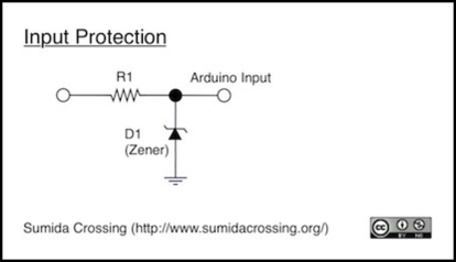
A zener diode should always be used in series with a resistance (which may be part of the input circuit, or dedicated to the zener) to prevent current during a “short to ground” condition from exceeding the zener’s rating (which is usually fairly low). Values around 100 Ohms (or in some cases even 10 Ohms) may be sufficient, too high and the ability of the zener to divert higher voltages will be limited. The diagram below shows a zener (D1) with a resistor (R1) used to clamp the input voltage. Note that placing the resistor between the circuit being monitored and the Arduino, as shown, allows the same resistor to serve as a current limiter when the pin is used for output purposes (as described above, the resistor must be at least 125 ohms on a 5V Arduino to provide that protection).
The specific ratings required will depend on the circuit. If this is not a battery powered circuit, then some leakage on HIGH is acceptable, and using a zener rated for close to 5V will work. One example is the ON Semiconductor 1N5338B, a 5W, 5.1V zener in axial form with 5% tolerance for around US$0.50. The 5W rating at this voltage means that it can tolerate a full amp of current, so the resistor could be as small as 5 Ohms (rounding up, 10 ohms is a better choice). However, unless you are working with something where you need to capture microsecond changes in circuit voltage, larger resistors are just as good and will reduce the current.
Since there is some tolerance to higher voltages on the Arduino, you can use higher-rated zeners to reduce current loss on normal HIGH signals. But be sure to consider the zener’s tolerance (at 5%, a 5.6V zener can allow 5.9V, but a 6V zener could allow a damaging 6.3V through). Finding these may be slightly harder, although in the case of a 5V Arduino, the 1N5339B, a 5W, 5%, 5.6V zener appears to be readily available and priced similarly to the 1N5338B. This, however, assumes the Arduino’s other components are really going to be safe at the maximum possible voltage. Having a larger safety margin, even at the cost of some power loss in current, is probably preferable.
Note: for 3V circuits, there is a 3.3V version of the above diode, the 1N5333B. This isn’t quite as good a choice since it clamps at exactly the rated Arduino voltage, meaning that it will let more current through on a HIGH signal (potentially as much current as R1 allows if it’s slightly below the nominal value or the circuit is higher-powered), but zeners rated slightly higher seem to be rare.
Changing Logic Voltage
Commonly referred to as “Level Shifting”, circuits that can change voltages used in signaling are useful in a variety of applications, but most often these are needed when you want to interface one device that operates at 5V (like an Arduino) to another that operates at 3.3V (many common CMOS-based devices). In some cases there are ways to connect these directly without further electronics, but often this risks damage to the circuits. A level-shifting circuit avoids that problem.
Level-shifting circuits come in several varieties. Simple ones work in one direction. More complex ones operate bi-directionally, for applications like the I2C serial bus often used to communicate between small devices. Finally, some circuits provide “isolation”, separating the two devices so that they do not need to share a common ground and each is isolated from electrical noise and other disruptions local to the other. A level shift circuit that works only in the down direction (e.g., from 5V to 3.3V but not the reverse) is called a voltage divider.
If you search the Internet, you will find a lot of simple, uni-directional, level shift circuits. Many of these will be familiar as components of more complex Arduino output circuits.
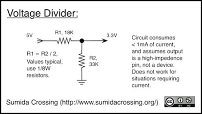
The simplest circuit is to just use a resistor to shed some of the voltage. This only works if the current is predictable, since the output voltage varies with current (Ohm’s Law). One application where it does work is a connection between two logic devices, where the receiver senses voltage without drawing a high current (i.e., is in a high-impedence state similar to an Arduino’s INPUT mode). The Simple Divider circuit in the above diagram provides this. Here, R2 is acting as a pull-down resistor, and R1 is discarding part of the source voltage before it reaches the sensing pin, similarly to how a resistor works to reduce voltage to a LED.
Note that the resistors have to be fairly large to keep current demands down. The actual formula relating the two is Vout = (R1 / (R1 + R2)) x Vin, which works out roughly to R1 being half the value of R2 when shifting from 5V to 3.3V (other resistances are needed for other voltages).
Beyond simple voltage division, you can also use more complex circuits to shift voltages up or to allow the pins to be reversed under software control (so that sometimes one side is the input and the other the output, and at other times the other side becomes the input). This is useful for serial communications lines, like the Arduino’s I2C (note that you need two of these, one each for SCL and SDA, to make I2C work).
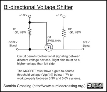
This above circuit works because the pull-up resistors keep the two sides at their respective full voltage, except when the FET is turned on. I’ll admit I don’t really understand the logic of how it works, but it’s a widely-used circuit. Note that FET selection is critical. The gate-source threshold voltage needs to be below 1.7 volts for reliable operation (some sources say 2.0 volts). Other characteristics are also important. Phillips has a nice application note on this, AN97055; there are many copies online, but I can’t find one directly from Phillips and I don’t want to link to someone else’s copy, so search for it if you are interested. The one noted above meets the requirements specified in Phillips’ note, and comes in a three-pin form that is easier to solder to than the surface-mount chips used on circuit boards.
Note: you don’t need to build a special circuit for this, actually. There are simple boards with level shifters available. Sparkfun sells a simple bi-directional model with two inputs and outputs suitable for normal on/off use, and a more complex one suited for I2C and similar high-speed bus applications.
Device Control
For switching devices that draw current, transistors are used. While simple transistor circuits can be used for many things, for larger power levels a Field Effect Transistor (FET), typically a MOSFET, is required. Two of the more common of these are the 2N7000, suitable for currents up to 100mA at voltages up to 60V, and the IRF510, suitable for currents up to 4 Amps (5.6 A if well-cooled) at voltages up to 100V. The IRF510 comes in a TO-2 case and should be equipped with a heat sink when used with larger voltages and currents. Note that both are for switching DC circuits in the circuit shown here. AC control circuits are possible, but more complex and a relay is probably a better choice for AC circuits.
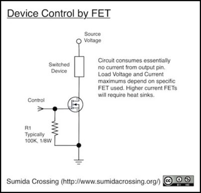
The diagram above shows a control circuit for switching power to a load on or off based on the output from the control on the left. When the control is HIGH, the FET turns on allowing power to flow through the switched device. Unlike ordinary transistors, FETs do not require an inline resistor on the control line, however a pull-down resistor (R1) is recommended to ensure that they turn off reliably. This can be fairly large to minimize current, 100 K Ohms is typical and reduces the control pin current to nearly zero.
On a larger-current FET in a TO-2 case, a heat sink will be required if currents get above 2A, or if airflow is restricted near the circuit or there are adjacent heat-producing devices. This may vary depending on the specific FET. To determine if a heat-sink is needed, take the maximum allowed junction temperature (Tja) and subtract the air temperature near the circuit (Ta, which may be considerably above room temperature) then divide by the junctions thermal resistance to ambient (R theta ja, often written as RthJA), to get the maximum allowable amps without a heat sink:
Amax = (Tja - Ta) / RthJA
So, for the IRF510, operating in a room at 35°C, this is Amax = (175 - 35) / 62 = 2.25 Amps. If constrained conditions raise the temperature near the FET to 50°C the limit becomes 2.02 A. Note that that’s the temperature at which connections inside the case melt, so it’s probably not a good idea to crowd too closely to that limit. A typical safety factor is 2:1, so if you’re going to run more than 1 Amp through the switched device, it’s time to add a heat sink.
