


Car Lighting: The Circuit Board
As described in the Overview, my goal here is to provide continuous power on a DCC system for interior car lights in Kato passenger cars, which have an annoying tendency to flicker due to the way power is conducted from the wheels to the LED lightboard. A simple capacitor circuit proved to solve this problem quite well, as a cost of about $2/car for components in quantity. Note that this circuit does not replace Kato’s standard lightboard, or alter it; all I’m building here is a “sustained” DC voltage source to feed the Kato board when track power is lost.
Note: Larger versions of the images here can be found in the Car Lighting photo album.
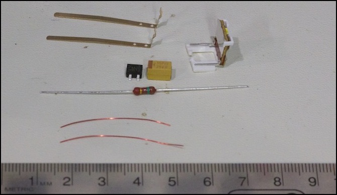
Components: rectifier (black), capacitor (yellow), resistor (brown), Kato lightboard (white/silver), wires
Components:
- Rectifier: Fairchild Semiconductor 58K1812 ($0.219 ea. in bulk)
- Capacitor: KEMET T491X107K025ZT, 100 μF Tantalum Surface-mount ($1.73 ea. in bulk)
- Resistor: Vishay PR01000101500JR500, 150 Ohm, 1W, 350 V, 5% ($0.076 ea. in bulk)
Note: the capacitor listed above was discontinued by the manufacturer. As of early 2017, Digikey has a replacement, part T491X107K025AT, with a slightly higher price. I haven’t checked the other parts, and only noticed this one because a reader comments on it.
Caution: if adapting this circuit for larger scales, I recommend using a larger capacitor rated for at least 35V, and 50V would be preferable. It’s a good rule of thumb that capacitors should be rated for twice the expected voltage, and DCC voltages can get into the mid-20’s. Capacitors fail destructively when over-voltaged, and I don’t think you want that happening inside an expensive model.
Now that I had the circuit proven, and knew how large my components were, I could design a board specifically to fit the available space. A bit of measuring showed that I had about 7mm between the seats in a standard Kato E231 commuter coach, which also happened to be the length of the longest component other than the resistor, and thus gave me my width. Length was less tightly constrained, but I had about 14mm from the plastic wall at the end of the car to the first window, and keeping the electronics out of sight was one of my goals.
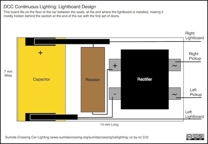
Lightboard Design (ideal size)
It was a pretty simple step from there to lay the components out. The rectifier is 5mm in its longer dimension, and 4mm on the shorter, but an additional mm is needed on each side for the contacts, making the space about 6mm. This leaves the AC pickups at one end of the board, where they can be wired to the L-shaped brass strips that slide into the end of the car. The surface mount capacitor is 7mm long, and 4mm wide, but the contacts are on the underside, so it can fit on one end of the board, with a contact strip made of brass or even bare wire underneath. Finally, the resistor will fit between the two with a bit of overhang, although it needs to be raised up slightly to clear the contact strips from the capacitor. The output wires also connect to those contact strips, and are wired to the actual Kato lightboard.
Note: This board is using the 100 μF Kemet T491 surface-mount Tantalum capacitor mentioned on the next page, not the larger electrolytic one; on the capacitor, the “+” end is marked, typically with a brown stripe or similar marking.
The Circuit Board
The first plan was to assemble the circuit on a small strip of 1mm styrene, allowing replacement if there is a wire or component failure. I was going to use Wire Glue instead of solder. Two strips of brass about 7mm long were glued to one end with ordinary styrene cement, to provide a mounting point for the capacitor and something to connect the other wires to. Before attaching things the strips would be lightly sanded with very fine grit sandpaper to remove any oils or corrosion (a pencil eraser could also have been used).
This didn’t work too well. The brass strips came off in the first attempt, and the resistor proved awkward to connect without a mounting hole. I gave up on the styrene approach after trying again: the wire glue was too runny for the confined space and bridged both outputs of the rectifier.
Instead I went with a chunk of prototyping perfboard with plated strips on one side. This works, although it’s a bit larger than the initial intent, and it takes a long time to assemble (about an hour, mostly because each component needs to be clamped differently before soldering).
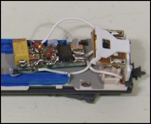
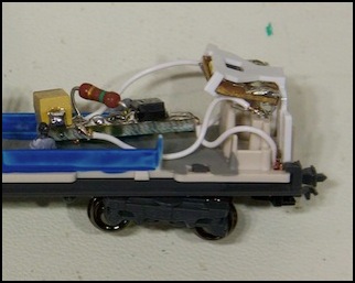
Assembled circuit board mounted on E231
It’s not a perfect design; assembly is still much slower than I’d like, and the board is a bit bulkier than I wanted. I’m tempted to etch my own boards. It shouldn’t be all that hard to do as a local store sells the needed supplies, and I used to do darkroom work, so I already have some similar experience to draw on. But I don’t really like playing with chemicals that much, and I’m not sure it really would make assembly significantly faster. For now, at least, I’m going to continue with the perfboard for my first complete train, and see if I get faster with practice, as well as seeing just how well a whole train looks with the small capacitors.
The bottom line: it works; the 100 μF doesn’t provide a long run-time, but it eliminates the worst outages.
See the Movies page for a short video showing an unprotected and protected car (using one of the prototypes) being pushed by the motor car.
