


I2C Bus
The I2C bus (formally written with a superscript, as I2C) is a short-distance serial bus designed for use on a circuit board, but it can also be used between two (or more) closely-spaced microcontroller systems, such as Arduinos, with some care. It is also called the Two-Wire Interface, or TWI, although that’s something of a misnomer as more wires are required if you count the shared ground. This page is focused on using I2C between computing devices like the Arduino, and for model railroad applications, although much of the basic information applies to any use of I2C. There are a number of additional features and characteristics of I2C I’m not covering here, as they don’t seem to be applicable to this kind of use.
There is a great deal written about I2C, much of it conflicting. You can probably find a source to contradict any statement on this page. But I’ll try to stick to fairly conservative specifications and the formal standards as much as possible. You may be able to work with longer bus lengths or different-sized resistors in practice, if conditions are right. I prefer to err on the side of caution and reliability.
The key point to keep in mind is that I2C was not designed as a long general-use bus. It was intended to be short and very carefully specified. Although it may be used to connect several related devices that are in close proximity together, it is not a substitute for a Layout Control Bus like LocoNet or LCC. Even the simple serial control busses will be superior to I2C in terms of noise immunity and signal reliability, which translates into usable maximum length.
That said, my intent is to use it for under-table applications with bus lengths of around 1 meter (3’) or less, which appears to be practical, although I need to do some testing to quantify that. I’m also looking at doing more general-purpose data transfer rather than the usual “set register X to value Y” or “read register Z” uses that are typical. The standard doesn’t preclude that kind of use, but I’ll need to write some code for error-checking and other features I can’t get from existing libraries.
Note: since this page was originally written for my Arduino section, and most of my use has been with Arduinos, it’s a bit Arduino-centric. I’ll add material on using it with other systems as I do more of that.
Software
The standard library for I2C support on the Arduino is the Wire library, distributed with the development environment. The name comes from Atmel’s name for I2C, the Two Wire Interface, or TWI.
I2C by any name is a master/slave protocol (more on that in the Bus Communications section below). The Wire library works well for slave devices, but is prone to hanging when used for master devices. There is an alternate library, for master devices only, called I2C (description available here, scroll down for download link). I2C allows timeouts to be set on transactions, so that the program can recover from problems occurring on the bus. Timeouts are not needed in Wire’s slave mode, as it uses interrupt service routines, so delays do not affect the main sketch code. I2C also provides more detailed feedback on operation status when errors occur.
I2C does have the limitation that it is not as flexible in terms of data transmission/reception as Wire. It always works on a complete buffer, rather than assembling a transmission from a sequence of separate function calls. It also assumes that the first byte of any message is a special “register” number. This means that a sketch would need to wrap the I2C routines in some additional code if some other format was needed.
I2C also provides a call for disabling the internal pullup resistors (more on why that’s important in the Pullup Resistors section below), rather than the calling program needing to manipulate the port directly to do that. That’s a nice touch.
I expect to use I2C on any code I develop for master devices, although my focus will probably be on the use of slave devices (using Wire) as agents for some more complex processor performing a controller function (and being the master on the I2C bus), such as a Raspberry Pi.
The standard Arduino Wire library does have one very significant limitation: messages must be no more than 32 bytes in length. It is always more efficient to send one longer message than it is to send two shorter ones, but unless you are trying to do bulk data transfer (such as moving a jpeg image), 32 bytes is reasonably long. Long messages are more likely to be corrupted by noise, so keeping messages as short as possible is preferable anyway, and you can send longer information as a sequence of 32-byte messages with only a minor hit on efficiency, so this isn’t a big limitation.
No error detection is built in to the I2C bus hardware or the software libraries, so if you want to detect and handle corrupted messages, you’ll need to add some kind of checksum validation to each message. This is fairly important, if the data is complex, as the probability of an error occurring rises with message length, and in an electrically-noisy under-table environment, the likelihood of errors is also increased.
History
I2C was originally developed by Phillips Semiconductors in 1982 as a control bus for use inside televisions, to eliminate wires and reduce costs. The name stands for Inter-IC bus, describing its role in connecting separate integrated circuits in a system. In 1998 they released version 2 of the standard, adding “Fast” (400 Kbps) speed to the original “Standard” (100 Kbps) speed (see the Speed section for more on this), and in 2007 version 3 was released with support for “Fast Plus” and “High-Speed” at 1 Mbps and 3.4 Mbps respectively. In 2012 revision 4 added a one-way “Ultra-Fast” form, with a speed of 5 Mbps. As of 2014 the specification is up to version 6, but changes since version 4 have been mainly documentary.
Phillips Semiconductors was spun out and renamed NXP Semiconductors in 2006, and NXP now owns and licenses the intellectual property related to I2C. To avoid paying licenses, a number of other companies have created equivalent-function hardware now that the basic patents have expired, which is why names other than I2C are often used to describe this kind of bus, although Wikipedia notes that the original name is not trademarked.
Bus Communications
The I2C bus can connect up to 128 devices, usually referred to as “nodes”. In our case, each node will be a separate computing device such as an Arduino. Although I2C can also be used for things like fixed-message-format sensors, that’s somewhat less useful in a model railroad context than more general-purpose communication between “smart” (i.e., programmable) devices.
I2C was designed with the assumption that one device was a controller, and all other devices were fairly simple things controlled by it. For that reason, all communications on the bus are managed by a single “master” device. It’s not really designed to allow two non-master devices to communicate, although you could write an application that did that by having the master periodically check for messages and pass them along. For example, if node A is master, and B wants to send data to C, it must first be picked up from B by A and then sent by A to C. Data rates between nodes other than the master are thus effectively half the nominal rate.
There is an I2C feature called multi-master that allows any node to become the master and initiate messages, but this isn’t supported by current libraries and greatly complicates the management of the bus. Using a single master as a switchboard, while less efficient, is going to be much simpler.
Two Arduino pins are used for I2C (hence the name “two wire”): SDA and SCL. The exact pin assignment varies by model of Arduino. However, the two devices have to share a common ground (they can be separately powered), so you may need a third wire if the two aren’t already grounded together.
Forms of Communication
The simple description of this kind of communication in Computer Science terms is a master/slave relationship. This describes the communication itself, but if you think of the task that communication is being used for, distributed problem-solving, the roles are more like coordinator/agent. Some central device (the master) keeps track of what’s going on, handing out tasks to or requesting information from other devices as necessary. The other devices each do whatever they wish with the received tasks, and report back whatever they think is needed. How they handle the received request is their decision. While data can be passed from one agent to another through the coordinator, it’s more likely that the coordinator will receive a message, and then form a different message to one or more other agents based on it.
However, you the programmer determine just how I2C is used. You could treat all nodes as equals, and have the coordinator merely acting as a switchboard between agents in addition to performing its own agent tasks, or you could treat it as a micromanager that hands out very specific tasks (e.g., “turn output 3 on”) leaving little for the agents to do beyond executing simple tasks. Or something in between, whatever works for your application.
The actual communication takes the form of the master issuing either a START command followed by an address with a “write” command and one or more bytes of data and a STOP to send information, or a START followed by an address and a read command, after which it receives one or more bytes of data from the addressed node (the number is determined by the master node) and then it sends a separate STOP to close out the transaction. It’s possible for data to be followed by an additional START and more data before the STOP is sent, but the destination and address are only defined after the first START. These are usually packaged up into simple library functions like beginTransmission, write or read calls, and an endTransmission, so the programmer doesn’t need to concern themselves with the internal detail.
One implication of this format is that either the size of messages have to be pre-defined (so everyone knows how many bytes are to be sent) or the end of a message must be internally marked (so the node knows when it can stop reading bytes).
One common method for dealing with pre-defined lengths is to use the first several bits as a command, where each command can have a separate number of associated data bits. Another method is to use the first several bits as a length (five bits for messages up to 32-bytes), followed by that many data bytes. The typical way to mark an end to variable-length data would be a special bit pattern that can’t occur within a message, such as a NULL (8 bits of zero) on the end of a string. As long as all the nodes understand how length is being marked, the need for pre-agreed lengths doesn’t actually impose much of a limitation on the kind of messages being sent.
Speed
Two of the usual I2C clock speeds are supported by the Arduino: “Standard” (100 kHz) and “Fast” (400 kHz). Although it would appear from the datasheet that the Atmel hardware used in the 16 MHz Arduino could support “Fast Plus” (1 MHz) as well (with TWBR register set to 0 on a 16 MHz-clocked Arduino), according to the NXP User Manual this rate is not supported and 400 kHz is the maximum. Clock speeds can actually be set to a number of values, 256 steps ranging from 489 Hz to 1 MHz, but there’s little reason to use a non-standard speed.
Speeds:
- Standard: 100 KHz
- Fast: 400 kHz
- Fast Plus: 1 MHz (unsupported on Arduino)
- High-speed: 3.4 MHz (unsupported on Arduino)
- Ultra-fast: 5 MHz, unidirectional (unsupported on Arduino)
In the Wire library, “standard” speed is the default. To set “fast” speed, follow the call to Wire.begin() with the undocumented function Wire.setClock(400000L) before doing anything else. Note that the “begin” function sets the clock to standard speed, so it must come before the setClock call.
But faster isn’t necessarily better. Before setting a higher speed, keep in mind that bus length is more limited as speed increases (see the Distance section below) and that at faster speeds the Arduino will have less time to process a message before the next one arrives if it is receiving back-to-back messages.
The actual data transmission rate is variable and less than the clock speed implies because one byte of address is pre-pended to some number of data bytes. At worst this will be about half speed (so 100 kHz equates to roughly 50 kbps), but with multi-byte messages the effective bit rate will be closer to the clock speed. E.g., with 10-bytes of data per message, the bit rate is close to 10/11-ths the clock speed, so 100 kHz will be close to 91 kbps. Some bits are lost to other purposes (ACKs, etc), which also reduces the effective rate slightly.
Additionally, when a master node has requested data from another node, the other node may delay the reply, called “clock stretching”. This isn’t commonly implemented, but it is another reason for the effective data rate to be less than nominal if a device implementing it exists on the bus. The Atmel hardware in the Arduino supports clock stretching, but it does not appear to be supported by the Wire library.
As noted at the top of this page, communication between devices would probably be done through the master, so for two non-master nodes the effective rate between them will be half the above.
In general though, speed of transmission will not be the limiting factor. The time it takes an Arduino to do something with a message and still have processing time left over for other things it needs to do will be more constraining unless a very large number of nodes are linked together and doing something fairly communications-intensive.
Interrupts and Other Overhead
An Arduino is fairly fast, but there are limits. On a master Arduino, the issue is mostly one of extended delays to the sketch loop, because the code will wait for the total time it takes to transmit a message. On a slave Arduino, we’re saved from that thanks to interrupt handling, but having too many interrupts is a problem in itself. These two issues are in direct conflict, so an individual application needs to choose some compromise that works for it. There is no optimal answer for everyone.
The times here are short, but they do add up. At the Standard speed of 100 kHz, a bit lasts about 10 microseconds (usec). At Fast (400 kHz) speed, one lasts only 2.5 usec. But a full 32-byte message will last around 3.5 milliseconds (3,500 usec) from start to end at Standard speed, and a series of short ones at Fast speed can use up something close to half of the Arduino’s capacity doing interrupts, which is a really bad state to be in.
Interrupt handling is an issue on the slave side, as the arrival of a message isn’t under the control of the receiving Arduino, and an interrupt is used to make the message available. There is one interrupt per received message, regardless of its length. However, that only applies to slaves receiving messages addressed to them (or to the broadcast address, if used).
The largest issue with interrupts is that while one is being serviced, no others can be. The Arduino uses multiple interrupts, for things like timers and the serial library, but they’re all suppressed when one is being serviced. If you spend too much time with interrupts turned off, clock pulses for timers will be missed, and timings will be wrong. How much of a problem that is depends largely on what the Arduino is doing. If it just needs to check duration between things to the nearest tens of milliseconds, it can tolerate a lot of error that is sub-millisecond in nature. If it’s trying to measure something more precisely, even small errors can cumulatively be an issue.
In an interrupt-driven system, the usual design is to keep the actual interrupt-suppressed code (the ISR or interrupt service routine) short, and just move essential things from registers to memory, so that normal code can process it later. On a slave receiving or sending data, there are actually two ISRs involved: a low-level one inside the library plus a user-defined function. The low level one copies data out to the working buffer the user routine knows about (plus doing a few other assignments). This is fairly fast, but still likely tens of microseconds. The key point here is that the user ISR should do as little as possible, probably just another copy of the buffer (inefficient to do it twice, but likely necessary) and then exit so interrupts will be restored.
There is also overhead to switch to and from the ISR, which takes a bit over 3 microseconds by one estimate. If we’re receiving messages addressed to us back to back, there is about 20 bit-times per message, or around 200 microseconds, for a one-byte message. Longer ones are actually more efficient, as the ISR won’t be called until the last byte is received. But if we spent 20 microseconds handling the interrupt between the low-level ISR and the user ISR, which seems like a likely time if we’re being efficient, that’s about 10% of our time. If we’re doing multi-message data transfers, we could have multiple back-to-back messages, so that’s something to consider, as it could create error in timers.
Once we’re out of the ISR, other interrupts can proceed normally. If we spend 20 usec in the ISR, we now have 180 usec (less any other interrupts we don’t know about) to actually do something with the received data. Note that it can take longer than that to read an analog pin, so back-to-back messages can be problematic unless we can queue them up to handle individually. An alternative is to structure the way the master works to ensure that it won’t send two messages to the same address without some interval between them.
A couple of key take-aways:
- it’s more efficient for the receiver to process fewer long messages rather than more short ones (fewer interrupts), and
- we may not be able to fully respond to one message before the next arrives unless we’re managing the sending end very carefully.
This appears to be manageable at 100 kHz. At 400 kHz things are happening four times as fast, and thus we have one-quarter of the time (e.g., 50 usec for a one-byte message) to process each message. But the ISRs didn’t get any faster, so now we could be spending 40% of our time in ISRs and trying to use the very limited remainder to process the message. For short messages, that’s probably not difficult. But for larger amounts of data, which is one reason we’d want a faster bus, keeping up with it gets harder.
It should be obvious here that there’s little real gain from running at the faster speed. At least for a slave node.
One the master side, things are a little different. There’s no interrupt involved, at least not in the libraries I know of. The sending code actually sits and waits while the hardware transmits bits, so it can manage the message from when it sends the START to when the ACK is received at the end. Thus longer messages are bad because the sender isn’t doing anything for longer periods. However, interrupts aren’t suppressed (at least they don’t appear to be), so this is really just a long delay for the sketch. Duration depends on the number of bytes in the message (plus the address, plus a few bits of padding), so a single-byte message probably holds up the sketch for around 200 microseconds at 100 kHz or 50 microseconds at 400 kHz. Longer messages take proportionally more time, and a full 32-byte message would lock up the sending Arduino for 3.5 milliseconds at 100 kHz. That’s not terrible, but it’s enough to have an impact on some things (like causing flicker on charlieplexed LEDs).
The take-away here is that there’s a balance to be struck between optimizing the interrupt frequency on the slaves, versus delays on the master. The former is more problematic in most cases, but it’s not the only issue.
Addressing
Every node other than the master must have a unique address. There are some modes of operation where multiple nodes can share an address, but these probably aren’t relevant to anything I’d do with I2C. Although there are a number of pre-assigned addresses, if the specialized devices that they’re used for aren’t needed, those numbers can be used as ordinary addresses. There are also a few reserved addresses, which should not be used.
In basic I2C, addresses are seven bits, so up to 128 nodes (1 - 127, plus the Master, address 0 is special) can exist on one bus. There is also a 10-bit address form, but this isn’t supported by Arduino’s Wire library. And, in fact, it wouldn’t be of much use. As we’ll see below, you can’t have more than 40 Arduinos on an I2C bus without exceeding the specifications anyway.
In formal I2C, a number of addresses are statically assigned to specific forms of hardware (e.g., things like sensors), and thus the addresses available are further restricted. If you are only working with programmable devices like the Arduino you can choose to use any address, although this is technically a violation of the standard. It’s probably a good idea to avoid the reserved addresses though. If you want to work with simple fixed-format devices that use I2C, such as LCD displays or RFID readers, you will need to know what addresses they use and avoid using those for your devices.
Several addresses are reserved for special uses, and should not be used as node addresses: addresses 0 to 7 and 120 to 127. This reduces the number of possible devices to 113.
Although not enabled by the Wire library, address 0 serves as a broadcast address and messages from the master to it will be received by every Arduino (if they enable it). It’s possible to enable this by modifying a register after Wire.begin() is called. The way to do this is to add the following line immediately after calling Wire.begin():
TWAR = (TWAR & 0xFE) | 1This preserves the address value stored in port TWAR’s high 7 bits, and sets the low bit to 1 to enable the “general call address” function.
Note: the above is specific to the ATmega328 and related processors (the Uno and similar Arduinos). It won’t work for variant Arduino’s based on other processors (like the Zero, which uses the Cortex M0 processor, or the Due, which uses the M3).
Power and Ground
I2C does not allow for electrical isolation between nodes. All nodes must have a ground in common for reference, and attempting to place an opto-isolator or similar between nodes will cause problems with the signal timing (there are bus-extender circuits, but those are not isolators).
Each node may have an independent power supply, however, as long as the grounds are tied together. In fact, it is possible (within limits, or with level-shifting circuits) to mix nodes with different supply voltages. One common example, discussed more below, involves mixing a 3.3V Raspberry Pi with 5V Arduinos (it’s also possible to connect 3.3V sensors to a 5V Arduino, or similar). In such a case, the lowest voltage of any node’s supply must be used as the pull-up voltage for the signal lines if level-shifting circuity is not used.
It is also possible to drive all nodes off one power supply, and this is often done when connecting devices to a controller. However, for a distributed system of Arduinos or similar, separate power supplies are preferable for both noise-reduction and current-limiting purposes.
Wiring
Maximum bus distance is affected by the type of wire used for the two signal wires. Use of Cat5 wire (pulled out of an Ethernet cable) will provide sufficiently high quality to get fairly good performance, although a flat (not twisted) ribbon cable may be slightly better, particularly if a common ground wire is run through it.
One interesting point: SDA and SCL are independent signals, so there is no benefit in using one twisted pair for those two wires. However, one of the recommended forms of wiring uses two twisted pairs, one for each signal with the signal wire wrapped around a separate grounded wire. This isn’t’ quite as good as the flat ribbon cable, but it’s close.
Good ribbon cable actually has better (lower) capacitance than twisted-pair cable (46 pF/m versus 52 pF/m is typical), so it’s slightly better as a wiring method, however it’s also harder to work with and the benefit is marginal, so the “two twisted pairs” method will yield similar performance with less work.
Although noise is a potential problem, shielded wire should not be used, as this affects the capacitance of the wire (capacitance in shielded cable is about double that of twisted-pair). If noise proves to be a serious problem, a shielded cable with the shield grounded at one end (or used as the common ground) could be used, assuming distances are kept short and/or data rates are relatively low.
On Uno and compatible Arduinos, signal SDA is pin A4 and SCL is pin A5. Wire all of the Arduinos pins to the corresponding wire (i.e., one wire connects to all SDA pins, and the other to all SCL pins). Keep the connection from the pin to the wire as short as possible (ideally, zero length).
Pull-up Resistors
One set of pull-up resistors are required for both SCL and SDA lines, but the internal pullup resistors on the Arduino are the wrong size (20 kOhm or more), and there’s a set on each Arduino, so don’t use them. Instead, add one pullup resistor to each wire (not one per Arduino, just one). A typical size is around 1.5 kOhm to 2.5 kOhm. The larger the pullup, the shorter the maximum bus length. However, smaller pullups increase power use. At 5V, a 1.5k pullup uses 3.3 mA per wire, while a 3.3k pullup uses 1.5 mA per wire, so the difference isn’t huge.
The reason for this is that the size of the resistor, in conjunction with the capacitance of the bus, affects the rise time of a pulse, and there are limits on that time (1.0 microsecond for Standard, 0.3 microsecond for Fast). While a number of online sources describe larger values for resistors, these are out of spec unless the bus is shorter than the maximum.
Per the ATmega data sheet, the minimum pull-up resistor value at 5V is 1,500 Ohms, and the maximum value is 2,500 Ohms. At Fast speed the minimum is the same, but the maximum (at 200 pF) is also 1,500 Ohms (both specified at maximum capacitance and 5V). The TI formula (see troubleshooting guide in References) agrees on the minimum value for 5V (if you plug the right numbers into the formula), but yields a much lower one for 3.3V (145 Ohms).
One of the NXP data sheets provides a chart of maximum allowed resistance by voltage and wire capacitance. The short answer is that 1.8 kOhms is a good value for both 5V and 3.3V. Larger resistances will work, but reduce either the maximum length or maximum speed. Lower resistances are undesirable (except for 1.5 kOhms on 5V). Actual current is very low, so a 1/8W resistor is more than enough.
A mentioned in the Power section, the I2C bus requires a shared reference ground. Although some discussions describe running this as a third wire, use of a star ground (all Arduino power supplies have their grounds connected to a single common point) may be simpler and less prone to noise injection into the ground. This doesn’t preclude also running ground wires with the two signal wires (twisted or in a ribbon cable), as long as those are connected to ground only at one end.
The pull-up resistors must connect a single power supply to the two signal wires. It is probably best to use the power supply of the master Arduino (but see the comment below about use with a Raspberry Pi). This power does not need to connect to the other Arduinos; as noted above in the Power section, it’s probably best if each Arduino has it’s own power supply to minimize electrical noise transmission between them though the supply line.
If you mix 3.3V and 5V equipment on an I2C bus, the pullup resistors MUST connect to a 3.3V voltage source. Using 5V could damage the lower-voltage devices.
When working with the Wire library, to disable the pullups add the following lines after the call to Wire.begin():
pinMode(SCL, INPUT);pinMode(SDA, INPUT);Although the 5V pullups will be enabled briefly, it may be short enough to avoid damaging sensitive equipment, particularly if protection resistors are used as described below. Measurements I made show that the 5V output is active for 32 microseconds, far longer than the 1 microsecond it takes to reach full voltage. Resistors won’t prevent that, but they will minimize any current flow, and that ought to limit some kinds of damage. However, I don’t know that an exposure this short would be safe. Even if a device doesn’t fail immediately, damage may accumulate over repeated events until it does. Ideally, the library ought to never enable the pullups in the first place. Failing that, use of a level-shifting circuit (see the discussion below) will shield the low-voltage hardware from any exposure to higher voltages.
Protection Resistors
Where a node connects to the two signal wires, protection resistors can be placed inline (between pin and signal wire) to shield the node from noise-induced voltage spikes. These are probably a good idea in model railroad applications, due to the potentially noisy environment. For a 5V node, the maximum allowed resistance per pin is around 300 Ohms. For a 3.3V node, maximum resistance is around 100 Ohms.
Distance
The maximum length of the bus (total including all nodes) depends on several interrelated factors, ultimately having to do with signal timing. The bus wire capacitance and propagation delay due to length are key factors, with capacitance usually the limiting factor. As a general rule there is a maximum limit of 400 pF of capacitance from wire and pin connections at Standard Speed (per the NXP User Manual, see references). The sum of all wire and pin capacitance must not exceed this amount. The wire capacitance of good wire is at best around 50 pF / meter, which limits length to slightly under 8 m (around 25’). However, this does not allow for full-speed operation at even standard speed. Additionally, each Arduino adds about 10 pF of capacitance, so with many nodes the maximum length is further reduced.
With Fast speed, this is reduced to 200 pF unless either a current source or “switched resistor circuit” is used in place of the pullup resistors. Since most people won’t do that, this means the maximum distance will be very limited if Fast speed is used.
Note: with a budget of 400 pF and 10 pF per Arduino, you can see that the actual limit on the number of nodes would be 40, assuming no wire at all. With 10 cm (4”) between nodes, which is probably as short as you can practically get, you could have as many as 26 modes before exceeding the specs. Of course that doesn’t mean that 30, or even 50, nodes wouldn’t work. It just means that it might not, or that communications might be “flaky”, as the signal wires erratically fail to fully reach the proper level in time for receivers to read the bit correctly.
If you consider the pull-up time, maximum wire length at standard speed is something less than 10m, possibly as low as 1m (per one recommendation, which may be overly conservative). At fast speed, maximum length is one-eighth of that possible at standard speed due to the combination of faster signaling and the lower capacitance budget. Thus Fast speed is really only useful for devices within centimeters of each other.
For best reliability, don’t get close to the limits. To be sure of operating within the safe performance bounds, it may be best to limit standard rate to around 1 - 2 m (3’ - 6’) of total bus length and high speed to closely-adjacent devices. However, there is substantial proof that longer distances are possible in practice.
Additionally, there are circuits that can extend a bus, although total propagation delay will then become a factor. Maximum lengths of tens of meters are possible, but may be very vulnerable to noise.
Working with a Raspberry Pi
Although the Raspberry Pi uses a 3.3V power supply (and is very vulnerable to over-voltage) and the typical Arduino uses a 5V power supply, it is possible to use an I2C bus between the two without the need for level-shifting circuitry. However, there is some risk to this as I’ll describe below, so use of level-shifting may be a good idea anyway.
The reason it is (somewhat) safe to do this at all is that nodes always pull the voltage to zero, and only the pull-up resistors pull the voltage high. As long as the pull-ups connect to a 3.3V power supply, the signal lines will never be pulled above a Pi’s safe voltage level. The Pi provides a set of 1.8 kOhm pull-up resistors on its board for these lines, so if you disable all pullups on the Arduinos, the Pi will pull the bus to the required 3.3V level (but don’t forget to disable the Arduino pullups!).
Note: if you forget, or have a bug in your code that begins the Wire library but doesn’t disable the pullups, you’ll probably fry the I2C interface pins on your Raspberry Pi, and need to buy a new board. So be careful if you mix a Pi with 5V devices, and in particular with Arduinos. This is another reason I think a level-shifting circuit is a good idea.
Connecting with 3.3V pullups works because 3.3V is high enough (just) for an Arduino to treat it as a “one”. Any voltage drop (long wires, poor solder joints, overloaded power supplies) may cause problems. So skipping the level-shifter will reduce the maximum workable length (or node count since that’s tied to the same limits).
Now for some caveats:
- The Arduino Wire library always enables the 5V pullup resistors, so you need to fix that as described above.
- The Mega2560 has hardware pullup resistors soldered to its board; you’d need to remove them to use it.
Rather than using the pinMode commands described above, you might want to modify the code in the Wire library to not set the bits to enable them at all. If you use code after the Wire.begin() as shown above, you’ll still have a momentary pulse of 5V down the lines that could damage a Raspberry Pi. It’s unlikely to last long enough to be a problem, but it is a risk. If you want to modify the software, see this site for an explanation.
The Pi has built-in pull-ups of 1.8kOhms. Use those as they’re the appropriate size for best performance with a 3.3V voltage source, and you can’t turn them off without using a soldering iron to remove them (not recommended). If using protection resistors, size those as 100 Ohms or less (actual current will be very low, and 1/8W resistors are sufficient).
It may be possible to include more than one Pi on an I2C bus, but those extra pull-ups would need to be disabled or the effective resistance would be too low for ideal operation. It’s probably simpler to communicate between two Pis using some other method (like Ethernet).
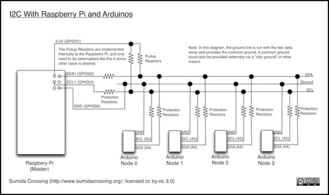
The following diagram illustrates one way to wire several Arduinos to a Raspberry Pi using I2C. This uses a third wire as the shared ground (ideally this would be the middle of three wires in a ribbon cable, if one with good capacitance were used). This is without level-shifting.
Level-Shifting
If you are going to mix 3.3V and 5V devices on an I2C bus, it’s really a good idea to divide the bus into 3.3V and 5V sections by inserting a voltage level-shifting circuit in the middle. You need to use one designed for I2C use, as many common level-shifting circuits won’t switch fast enough to keep up with the signal. Both Adafruit and Sparkfun sell a four-channel level shifter based on the BSS138 chip that is suitable for this. I2C only needs two of the four channels: one for SCL and one for SDA.
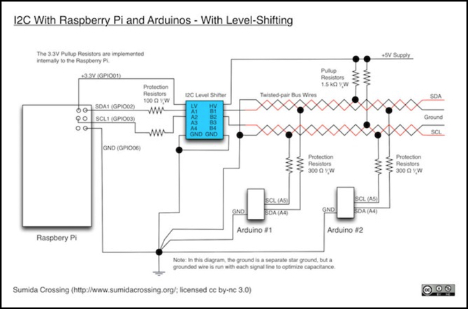
The following diagram illustrates how a level-shifter would be used. This diagram also shows the use of a central “star” ground and twisted-pair wires for the bus.
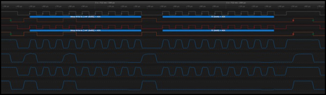
The screen-capture below shows I2C in action, captured by my Saleae logic probe with an I2C protocol decode (blue boxes). This is a single write of a binary zero byte to a temperature sensor (it’s what I had handy) with address 0x90 (binary 1001 0000) including the zero write bit. The left side is the start (data and clock pulled low) followed by the address on the data lines, and the right side is the data. Analog sampling was at 3.125 MHz (digital at 100 MHz, but that gets stored in a compressed form).
Note: while my probe isn’t the cheapest model they sell, you could make these measurements even on the entry-level one, since it will sample analog at twice the speed I was using and I only needed four inputs for this comparison.
This also shows the effect of a level shifter, since I was using a 5V Arduino Uno as the master and the sensor used 3.3V. A Sparkfun level shifter was placed between them. Both sides used external pullups (1.5 kOhm to 5V for the Arduino and 1.8 kOhm to 3.3V for the sensor). I did not use protection resistors for this example. The “wiring” was actually a breadboard with a bunch of 3” (7.5 cm) wire jumpers, so it was short but probably not ideal in terms of capacitance. Clock speed was Standard (100 kHz). This also shows the effect of the level shifter.
From the top:
- SCL 3.3V side (digital)
- SDA 3.3V side (digital)
- SCL 5V side (digital)
- SDA 5V side (digital)
- SCL 3.3V side (analog)
- SDA 3.3V side (analog)
- SCL 5V side (analog)
- SDA 5V side (analog)
The digital traces are the probe’s interpretation of the signal as 1 or 0, so they’re going to be clean. The only time these would matter is if the analog 1 wasn’t seen as a digital 1 (or vice versa for 0). The analog signal shows the waveform, with about 30 measurements per pulse, so it’s a fairly accurate representation.
While it might look as if the level-shifter is degrading the signal (the 3.3V side is slightly distorted in analog), that’s not the case. The signal looks similar when the sensor is transmitting. This is either an issue with the breadboard on the 3.3V side, or just extraneous noise due to the way I had the probe connected. In general the signal is quite clean, with pulses at their peak for most of their duration. I’m going to use this image as a reference as I experiment with longer and different wiring.
Also, although you can’t tell from this picture since the waves are scaled, the probe stores the voltage per sample and the voltage levels were correct. The 5V side had a few spikes to 5.2V (actual voltage on the Arduino 5V pin was 4.9V so that’s a 6% spike), but the 3.3V side was generally right at 3.3V.
References
There are several useful sources for additional material.
Arduino Wire Library documentation.
This is a bit spare on detail, so see the detailed reference as well.
Arduino Wire Library, Detailed Reference.
This goes into much more detail on how Wire works.
I2C Bus Specification.
This is a detailed write-up. At the bottom of the page there’s a link to the 64-page PDF NXP User Manual if you really want details.
I2C - Two-wire Peripheral Interface.
This is a good discussion of I2C and the Arduino Wire library, with lots of code examples.
Sparkfun has an I2C Tutorial.
Note that Arduinos don’t support multi-master configurations or 10-bit addressing discussed in this tutorial. Technically the hardware does support multi-master, but you’d need to write your own library.
Texas Instruments Application Report SCAA106: Troubleshooting I2C Bus Protocol (PDF)
This is a very detailed summary of what can go wrong, and how to check for it. It also has lots of interesting little details, including the formula for calculating pullup resistor min and max values, however that seems to assume a 1.8V bus, so don’t take the numbers at face value.
Another index of useful I2C material can be found here.
