


DCC and Lightboards
In a model train, typically the headlight(s) and tail-light(s) will be controlled via a simple circuit that’s placed on a circuit board called the “lightboard”, often the lights are mounted to the board as well, and either positioned behind small lenses, or transparent plastic structures (which may be tinted) called “light pipes” that direct the light to the headlight or other fixture. On a DCC layout, these can provide directional lighting due to the change in polarity when a train reverses (the “right” rail is positive when the train is moving “forwards” from the point of view of an imaginary engineering aboard it).
In many trains DCC decoders are sold as plug-in replacements for the lightboard: simply remove and discard the lightboard (keep it for testing purposes, actually) and install the DCC board. Or, in some cases, the lightboard has a socket for a DCC decoder, and you just need to plug in a standard decoder. That seems simpler, but in the confined space of an N-scale model it can be hard to fit a socket and second circuit board, so it’s not very common. If you are wiring your own DCC decoder, then things get more complicated.
Note: lightboards aren’t always as simple as those diagrammed here. Some manufacturers use “constant voltage” control chips, to try to keep the brightness constant as track voltage changes (and incidentally protect against overpowered track). There may also be other circuitry on a lightboard (Tomix uses a “constant lighting” system that puts AC power on the track atop any DC voltage, so lights can remain on even when the train is parked; you usually have to disable this in a DC environment).
Wiring DCC to an Existing Lightboard
Wiring a lightboard if you aren’t using a bipolar output has some issues. First is that you need to cut some of the traces on the board, both to insulate it from the track, and to possibly to allow the two sets of lights (head and tail lights) to be individually controlled. This can be problematic if they share a resistor. A lightboard will often use series wiring, and one shared resistor, and when modifying it you may need to add separate, larger, resistors to make the circuit safe. If you get it wrong, the LED may go “zap” (12V is enough to kill most LEDs).
The following are some generic diagrams of how lightboards might be wired. There is plenty of room for variation, and each case needs to be analyzed carefully to determine just what is going on.
Note: if the lightboard is also used to route power to the motor (and in locomotives they often are), it will have additional traces needing to be isolated from the motor, and may additionally have a capacity across the motor traces. If there is one, it needs to be removed, as these are to filter motor noise on DC, but will interfere with DCC signaling if they are still connected to the track pickups.
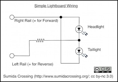
A simple lightboard circuit for directional lighting from DC track
With LEDs, you usually want a resistor on each LED for the simplest circuit, because no two LEDs draw identical power. Two LEDs in series can share a resistor (and it would be smaller than one dedicated to a single LED and run cooler), but two LEDs in parallel cannot: one will typically be much brighter than the other if you try. Red and white LEDs are particularly problematic, as they have significantly different power needs, and red LEDs in parallel to white will steal all of the power from white ones, leaving them dark. Note that two LEDs in parallel but reversed act like a single LED since only one is on at a time; head and tail lights wired this way can share a resistor, and if it wasn’t obvious that’s what’s going on in the diagram above.
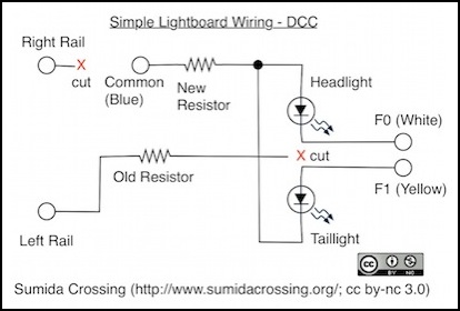
The simple lightboard, modified for DCC
DCC decoder function outputs (see RP-9.1.1, PDF) use a positive (+) common wire (color-coded blue) and negative (-) function “output” wires, which is the reverse of what you might expect. To modify a lightboard that controls both head and tail-lights for operation on DCC, you need to use two function outputs. Typically F0 is used for headlights (color-coded white) and F1 for taillights (color-coded yellow). If the resistor on the lightboard was on the positive side it could be reused, but it’s only on the positive side for one LED if the board has both head and tail lights, and so you’d need to add a resistor or do a lot of rewiring to use the existing one. It’s probably simpler just to cut the old one out of the circuit, and add a new resistor. onto which the blue (common) wire connects, as shown in the diagram above.
It may not be obvious, but in the following diagram the front headlight and rear taillight are parallel to each other, and thus need separate resistors as shown (ditto the rear headlight and front taillight). But the head and tail-light for each end are reversed, and so never operate simultaneously, and thus can share a resistor sized for one of them. This actually makes this kind of board easier to wire for DCC, since the common can go at the top left and there are already the two resistors needed. The middle left rail link would be cut and replaced as in the simple lightboard diagram above.
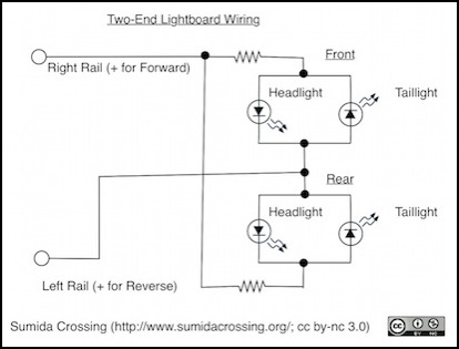
Two-ended Lightboard for directional lighting from DC track
Bulbs Need Resistors Too
Older trains may use 16V bulbs instead of resistors, and unlike LEDs those don’t need a resistor in series when used on DC. But perhaps surprisingly, when connected to a DCC decoder’s function outputs, they do, or at least it’s a REALLY good idea.
The main problem here is that a cold lightbulb draws a lot of power when starting up, used to heat the filament until it glows. Once it’s hot, the power level drops to that used to keep it lit, which is typically around 60mA for the small bulbs used on trains. The start-up power demand means that the current used by the bulb will be very high for a brief time (the technical term for this is an “inrush current” since the current rushes in at the beginning). Just like with motor decoders and stall current, if the decoder tries to supply more current than it’s rated for, it’s likely to destroy itself in the process. A decoder manufacturer might design to survive that kind of current for the short time needed, even if their decoder’s normal output was rated lower, but unless they specifically say so, don’t count on it.
Credit where it’s due: I first learned of this from a posting on JNS Forum by “mrpig” (Gordon), although Don has a nice write-up on Akihabara Station.
There’s a second issue to worry about as well. Trains on DC typically have about 3-5 volts on the track when the train is running, and none when it’s stopped. Trains on DCC have the voltage of the function output (likely 1-2 volts below track voltage) at all times power is applied. This will cause the bulb to run much hotter, and brighter, than usual. This could be enough to melt plastic in some cases, and it’s going to shorten the life of the bulb significantly. A resistor drops the voltage, and will make the bulb run cooler and last longer. Of course the resistor will pump out the missing heat, but hopefully far enough away from the bulb that they’re separate heat sources, and not directly touching the body shell the way the bulb could be.
Note: it’s also possible they use 12V or smaller bulbs, and already have a resistor to protect them from 16V or higher track power. Reusing that may be safe (it should handle the inrush current issue), but will likely still leave the bulb running hot.
How Big a Resistor?
How big this resistor should be is an interesting question. It’s basically handling a short circuit, but only very briefly so you don’t need to worry (much) about the short-circuit current (which is as close to infinite as the decoder can supply, for a very short time). Instead it needs to be sized for the normal power level it’s going to dissipate, based on the normal current required by the bulb. Too large a resistor will significantly dim the light, too small and it may not block enough of the in-rush current. I’ve seen a recommendation that 22 ohm or 33 ohm resistors are appropriate, and that these need to be 1/4 Watt for bulbs up to 75mA, or 1/2W for bulbs up to 100mA. If those work to limit the in-rush current to a safe level, then larger ones will also work, with a greater voltage drop.
Note: Digitrax also recommends a “22 to 33 Ohm 1/4 Watt Resistor” for bulbs using more than 50mA.
For a 60mA bulb with a 33 ohm resistor, in normal use the resistor will drop ~2 volts from the supply voltage (V=IR, 0.60x33=1.98V). That’s not going to dim the light much, and will dissipate ~120mW (P=VI, 1.92x0.60=0.115, 115mA), so a resistor rated for 1/4 Watt is indeed fine.
Note that if there is more than one bulb in series, the current will be the sum of the bulbs (e.g., 2 sixty mA bulbs in series is drawing 120 mA through the resistor, so a 33 Ohm resistor will drop four volts, and dissipate ~240 mA; a 1/4 watt resistor may still be okay, a 1/2W resistor would be better).
However, even if you plan to run on a normal N-scale DCC system with “12 volts” on the track, you may want to dissipate more power, to drop the voltage lower. Let’s assume you have a real “12V” supply but aren’t losing any in the track (you might have more volts, or lose a couple before it gets to the train), and lets assume you lose a volt going through the decoder (close enough). That means that if you can drop 5 volts in the resistor, you’ll have 6 volts at the bulb, which is still enough to be quite bright, but close to the normal level it would operate at on DC. A bit of Ohm’s law (R=V/I in this case) reveals that this would take an 83 Ohm resistor. It turns out that 82 Ohms is a standard 10% resistor size. Power dissipated (P=VI, where V is the 5 volts lost in the resistor) would be 300 mW, so you’ll need a 1/2 watt resistor.
But if you want something more portable, this gets complicated. The NMRA’s S-9.1 DCC Electrical Standard (PDF) warns that N-scale decoders need to handle up to 24 volts, and those for larger scales up to 27V). Most HO-scale DCC power packs have a track voltage around 16 - 18 volts, but some are reported to be up to 22 volts. Dropping 5 volts from 16 is still about double the bulbs expected voltage, and dropping 5 from 22 probably leaves the bulb above it’s maximum rated level. However, using larger resistors to drop more volts means more power is being dissipated in the resistor, and it rapidly becomes impractical. To drop 10 volts, you’d need to dissipate 0.6W, meaning a 1W resistor is needed. That’s getting a bit large to fit in a train. And if you really did run it on a 12V supply, you’d have a very dim bulb.
So the bottom line is that you probably don’t want much more than 5-8 volts dropped in the resistor, and for maximum life you should run such trains only on DCC systems that put out the 12-14 volts of typical N-scale DCC command stations. An 8 volt drop yields just under 0.5W, so a 1/2W resistor will work. To get that you need a 133 Ohm resistor. You can get 130 Ohm resistors in a 5% grade, which should be easy enough to find, or 120 Ohm resistors in 10% grade. I’d actually recommend the 10%, 120 Ohm resistor in 1/2 Watt size, as it has a better safety margin. That will drop 7.2 Volts, making the bulb voltage about 3.8 volts unless you have very dirty track, which might be a bit dim. You can back that down to 100 ohms or less if you want more light.
