


LCC for Arduino
I’ve added this page to collect information related to using Arduinos with the NMRA’s new Layout Command Control (LCC) standards, and specifically for information about CAN Bus shields available for it.
LCC depends on more than just the CAN Bus, as there is an LCC protocol used over the bus. The OpenLCB library provides support for both LCC and a subset of CAN hardware. Most shields and boards come with CAN software intended for use in automobile diagnostic applications. If the OpenLCB library does not support a specific board, additional programming will likely be needed to make the OpenLCB LCC code work with the shield’s native CAN library. At present (fall, 2015) it appears that only the Sparkfun shield is both supported and in production, although the Jaycon shield may also work. The OpenLCB library is also a fairly stripped-down subset of the standard, originally created for demo use and not obviously updated since then. You may need to extend it, or even rewrite it, if you’re going anything serious.
Note: while the OpenLCB libraries include a CAN library (and likely depend on this specific library), this is apparently based on an older library created for the Roboterclub Aachen e.V. (Aachen Robot Club) by Fabien Greif, which supports the MCP2515 (a common controller used on most Arduino shields). This version is described as “adapted and extended by Alex Shepherd”. A better choice today would probably be Neil McNeight’s CAN_Library, which is a compilation of several libraries (including the Aachen one, although apparently without the Shepherd modifications) and supports the MCP2515, AT90CAN family of AVR processors, the SAM3X ARM processor (used on the Due) and the K2X controller used in the TeensyDuino. Some adaptation of OpenLCB routines is probably required to use this library. It’s also a “cleaner” library in the sense that it was formatted to use the standard Arduino approach to libraries and made consistent with a recent version of the Arduino software (version1.6).
LCC Wiring
LCC requires at a minimum four wires arranged as two twisted pairs (i.e., a basic Ethernet cable). However it is preferable to use Category 3 (or better) cables with four twisted pairs. Some inexpensive cables are still made to the original two-pair standard, but anything described as Cat3 (or Cat5, 5e or 6) should have all four pairs. Ethernet cables must be normal, not “crossover”, cables (the latter are often sold for certain residential Internet uses like game system connections).
CAN wiring is a linear bus. This means that there are no branches and one end cannot connect to the other in a loop. There will be two end nodes that connect to only one other node, and all nodes between them will connect to exactly two neighbors. The nodes at the end would normally have terminating resistors connected across the H/L lines. These are provided on some shields via a jumper.
Note: short “stubs” are allowed, but these are basically for single nodes and shouldn’t be longer than 1.75m (5 feet), and there’s a limit of about 8.8m (29 feet) total of stubs.
A repeater (or bridge) can connect two bus lines together. It’s possible that an Arduino Due with its two controllers could be made to function as a repeater (and this would be a lot cheaper than commercial CAN repeaters, which cost several hundred dollars). This would likely require some programming, as I haven’t found an example sketch that does this.
Because CAN is a bus, a single CAN controller is really driving two interfaces. Although shields typically come with one DB9 connector, a short cable can be assembled that attaches this to two RJ45 connectors. Notice that the two RJ connectors are wired straight through (e.g., pin 1 to pin 1 and so on). The DB connector provides a ground on either or both pins 1 & 2 (depending on the maker of the shield), which should be connected to the common ground used by the shield circuitry (i.e., the ground of the Arduino board).
Note: there’s a potential bit of confusion in the wiring terminology. One of the ground wires in a CAN Bus is called the “shield” (formally the CAN_SHIELD). This has nothing to do with the fact that Arduino add-on boards are also called “shields”.
There is, unfortunately, more than one DB9 pin arrangement in use. In particular, there is a CAN in Automation (CiA) standard CiA 303 (CANOpen) that many devices use. This puts H, L and Ground on pins 7, 2, and 3 of the DB9. The Sparkfun Arduino shield (V1.2 and earlier), and several other shields, do NOT use this standard, and use a different one (apparently found on some OBD systems) using pins 3, 5, and 2. Version 1.3 of the Sparkfun shield adds the CANopen pins as an option (labelled “CAN” on the shield).
The following diagram shows the adapter cable for an Arduino shield to connect to an LCC-style bus (using the original OBD pin assignments). Note that pins 3 & 6 (the ground and shield wires) must be connected to each other and to the Arduino’s ground, per the LCC standard.
Note: I haven’t actually built and tested one of these, so it’s possible that I got something wrong and that wiring this up would fry a shield or some other component on the bus. I’m pretty sure it won’t, and that it will work fine, but use at your own risk.
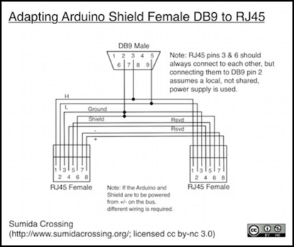
Diagram has been updated (but is still for v1.2 shield)
In the basic four wires, two are used for H/L signal lines, one is a reference ground and the fourth is a shield ground that is doubled-up with the ground line (the name is a bit of a misnomer, since shielded cables are not used; I expect this is a holdover from automobile wiring with DB9 connectors, where a shielded cable is more likely to be used). Two optional lines (marked “+” and “-“ above) provide a low-amperage power supply (7.5 - 15 V @ 500 mA) for powering bus-powered devices. The last pair of wires is reserved for future use. Technical note TN-9.7.1.1 says that in addition to simply wiring pin 3/6 to the common ground, a small resistor/choke filter can also be used to isolate the signal ground from noise on the power ground if both are connected.
LCC also allows screw-terminal connections to be used, provided that an Ethernet RJ connection is available as an option.
Terminating LCC
A CAN Bus is a type of “transmission line”. This means that it’s basically a radio-frequency (RF) wave guide. That’s a difficult concept if you’re used to digital circuits, because even through the bus is carrying digital data, it’s fundamentally using analog transmission at high frequencies to do it. One of the odd characteristics of that is that when the signal gets to the end of the line, it will “reflect” back. Think of it like a wave in water traveling from one end of a narrow channel to the other: at the end, the energy in the wave is redirected back, causing the wave to reflect off the end of the channel. In a wave guide, those reflections are attenuated due to resistance in the wire, but they can cause interference for nodes near the end of the bus.
Now on a short bus, you won’t encounter that, because the transmitter on the furthest node is close to the receiver on any node, and drowns out the reflection. But the longer the bus, the more those reflections become a problem. The solution to this is to damp out the signal at the end of the bus. And the way to do that is with a terminating resistor at each end.
If you omit termination, a CAN Bus may work. Or most nodes will work and some combinations won’t. This leads to all kinds of hard-to-debug problems, so don’t omit the termination.
Now for complex physics reasons, there’s more than one way to skin this cat. You can put a 60 ohm resistor in the middle of the bus, or a 120 ohm resistor at each end, or even do a split resistance methods with two 60 ohm resistors to ground at each end. If you look around for discussions of CAN wiring or read transceiver data sheets you’ll probably find all three mentioned. The LCC standard doesn’t specifically address this other than to say “conform to the CAN requirements” (i.e., use termination of some kind). TN-9.7.1.1 is a bit more helpful, and describes the three methods, as well as some others that it says should not be used.
The simplest solution is probably the best. When you arrange LCC nodes with dual RJ45 connectors, the one at each end of the bus will have an open jack. Plug an RJ45 plug into the open jack with a 120 Ohm resistor across pins 1 & 2 and those will terminate the bus. When you add a node on the end, move the resistor to the new end node. Note that any “stub” nodes will also have an open jack, but should not have resistors. There must always be exactly two terminating resistors on the bus (using this method).
To paraphrase Monty Python: “Two shall be the number thou shalt count, and the number of the counting shall be two. Three is right out.”
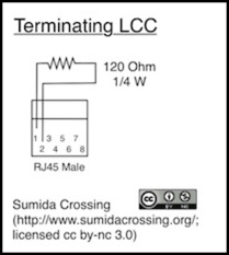
One interesting side comment: There’s little written about the power rating of the resistor. The LCC technical note says 1/4 W. In most cases that’s going to be fine. I will note however that the tech note implies that the voltage on one of the signal lines can be as high as 27 volts. That only happens if it accidentally gets shorted to DCC or something. But if it did, that poor little resistor is going to end up carrying something like 6 Watts, maybe half that if you’re lucky. But only for a very short time before they both go “poof” and let out the magic smoke. Since shorts like that aren’t very likely, and 10 Watt resistors are big and expensive, you probably are better off using the 1/4 Watt resistor and just planning to replace the termination if you ever screw up the wiring and short to a power bus. Just something to remember to check if you do have a short.
JMRI and Other Computer Support
While JMRI supports LCC, at present (Fall, 2015) no USB-CAN connectors are listed in the supported hardware section.
There is a CAN-USB adapter made by Peak, available from several suppliers, that has monitor applications available for Linux, Windows and OSX. The adapter comes in non-isolated (US$255) and isolated (US$325) versions. I’d recommend the isolated version; it’s cheap insurance for your computer’s USB port. Although this won’t support JMRI, at least not today, it could be used for simple testing of compatibility. Note, however, than the pinouts of the DB9 connector on the Peak do not match those on the Arduino shield, and an adapter cable would need to be made, using different pins than the adapter cable shown above. The OSX software (MacCAN) for the Peak provides a simple library and a monitor application that can send short (8 byte) CAN messages.
If you just want to monitor the bus, I turned up a USB-based logic probe that will do CAN decodes, from a company called Saleae. There are a number of good reviews out there if you look around. One thing to be aware of: the inexpensive model, Logic 4, doesn’t support the low-voltage range needed to decode the L signal line. You may be okay using just the H signal line if you aren’t building your own transceiver circuits (but you might want to ask them). There are also knock-offs of them, although I wouldn’t recommend those. And there are probably other, similar, devices on the market that will decode CAN if you hunt around.
CAN-enabled Arduino Boards
There are not a lot of Arduino boards with built-in CAN support, but there are a few.
Arduino Due: US$50
This has partial CAN support, with two controllers built into the microprocessor. However a shield is still required to add the pair of transceiver chips needed to utilize the controllers. Since the shield only needs the transceiver, but two controllers, a normal CAN shield isn’t going to do the job. You’ll need one specifically designed for use with the Due.
HobbyTronics Leonardo CAN-BUS: UK£23.40
This is a Leonardo-compatible Arduino with CAN controller and transceiver chips on the same circuit board. Behavior is apparently functionally identical to the Seeed Studio shield, as the link to the same library (they also link to a separate library, which may be a derivative of it). Note: the Leonardo is now “retired” by Arduino, so this probably isn’t a good choice.
Railstars
Railstars previously made the io:duino, an Arduino based on the AT90CAN processor with a MCP2551 transceiver chip. This met the LCC requirements, with dual Ethernet connectors and the blue/gold buttons used for LCC event association. Unfortunately the company is no longer in business.
Shields
There are two basic parts to a CAN circuit board: the transceiver and the controller. Normally, each of these is a single standalone chip. Atmel’s AT90CAN series of AVR microcontrollers (the AVR is the type used in the Arduino) includes a single CAN controller, but an external transceiver will still be required. The Arduino Due uses an Atmel ARM SAM3X/A series microcontroller that includes two CAN controllers, but similarly a shield with transceiver chips is still needed. Software libraries are available from the OpenLCB project to allow the Arduino to work with LCC. These support shields based on the MCP2515 controller and MCP2551 transceiver chips. which would work with most Arduinos. It’s unclear to me at present if these libraries would work for the Due or an Arduino built using a AT90CAN (although the now-defunct io:duino used that chip with those libraries, it may have been using a customized version). However, as noted at the top of this page, there’s a more recent library for CAN that does support them, and the OpenLCB code could probably be modified to use it.
Notes:
1) at a list price of US$50 the Arduino Due is fairly expensive for an Arduino, in part due to its higher-performance processor. Solutions based on the Uno or similar boards and a shield will be less expensive overall, although this depends on the specific shield used.
2) Most shields use DB9 connectors (one per transceiver) rather than LCCs required RJ45 (two per transceiver). While DB9 connectors are standardized for the automobile OBD application, this connector doesn’t meet the requirements for LCC electrically; the connector lacks the shield/ground pins required in the standard, although those could potentially be added to an RJ connector fitted externally. The power lines appear to meet the requirements for the optional LCC power lines for a bus-powered device, however the lines are rated for exactly 12V on some devices (normal automobile voltage), rather than the 7.5 - 15V permitted by LCC, so it is uncertain if bus-powered shields would be fully LCC-compliant.
CuteDigi LinkSprite CAN-BUS Shield: US$13
This is a basic single-controller shield with a DB9 connector, including both controller and transceiver chips. The OBD pinout is used: pins 3/5 are used for the signal H/L wires, and pins 9/2 for +12V/ground (a second ground is on pin 1). A switch is provided to break the +12V connection and a jumper is included for a terminating resistor. A tutorial is available from LinkSprite and includes a link to their library (note that both are focused on automobile applications).
DFRobot
DFRobot previously made a CAN-BUS shield, but it was discontinued in May 2015. It is unclear if a replacement is planned. The original did not use controller/transceiver chips compatible with the OpenLCB library.
JayCon CAN BUS Shield: US$20
This is a partially-assembled kit (the chips are soldered in place, but you need to add headers and bus connections). It appears to be compatible with the SparkFun shield, so libraries for that will probably work. And more importantly, it comes with the board designed to allow addition of two RJ45 connectors, making it a natural for LCC. I’ve ordered a set of shields to play with, so I’ll have more to say in the future, time permitting.
Sparkfun CAN-BUS Shield: US$25 - This is the only shield that I am certain will work with the OpenLCB library, although others based on the same chips may.
This is a basic single-controller shield with a DB9 connector, including both controller and transceiver chips. Pins 3/5 are used for the signal H/L wires, and pins 9/2 for +12V/ground. A CAN library is available from the manufacturer, and the OpenLCB library notes support for it.
Note: this was updated to v1.3 in October 2015; there don’t appear to be significant changes other than the pin customization mentioned at the top of this page, but I don’t have one to play with yet.
Seeed Studio: (price varies)
This is a single-controller shield sold through a variety of resellers, with prices as low as US$25. The shield uses the standard controller and transceiver chips, and includes a power switch for the +12V line. It has a single DB9 connector. The OBD pinout is used: pins 3/5 are used for the signal H/L wires, and pins 9/2 for +12V/ground (a second ground is on pin 1). (I had misread the documentation the first time I read it, but a subsequent re-reading clarified things; they don’t actually give pin numbers in their documentation, just a diagram of the DB9).
Togglebit Arduino Due CANShield: US$50
This is a shield specifically designed to work with the Arduino Due. It includes two screw-terminal connectors for the H/L wires for each controller, and jumpers for adding terminating resistors to each. It also has a large prototyping area for assembling additional custom circuits.
