


One Point Five Meter Line
What can be done in a very small space to make a diorama with a bit of action? That was the challenge I set myself, as both a way to display some of the structures built for my layout, and as a way to show of my Arduino-based Tram Controller.
Note: larger versions of these diagrams are in the Arduino Diagrams album, along with other diagrams related to the controller. And I now have a Construction album for construction photos.
Both the track and the small platforms I’m likely to use that go with it are described on my Tomix Fine Track page. However, my latest thought is to scratchbuild low platforms (or perhaps use the new ones from Kato, more on those later).
This project was set aside and not worked on for a long time, mostly because I needed to work on the Arduino software and it was more complicated than I anticipated. At present it’s still on hold.
Here’s the basic idea:
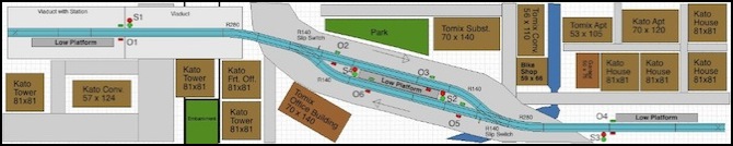
One Point Five Meter Line, revision 4
And here’s what it looks like so far:
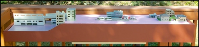
First building mock-up on completed box structure
I started with a plan for a layout 1.5m (5 feet) long, and 33 cm (one foot) deep. This was designed for table-top display, with the left end dropped slightly so that the line can be placed on an elevated viaduct station. The left end will be urban, the right end will be suburban with a strong residential character, and the middle will blend the two with a residential/commercial feel.
Construction
One problem with that design is the difficulty of getting either plywood or hardboard for the structure and sides in 5’ lengths. I thought I’d need to buy a whole 4’ x 8’ sheet, for a couple of 6” (15 cm) wide strips. The original plan was to make it sectional. But then I’d need to deal with making track connections, and a non-continuous fascia.
I toyed briefly with the idea of making it four feet long instead of five, as I can get 2x4 plywood panels fairly easily. Then Tossedman on the JNS Forum suggested using a Baltic Birch panel, and that solved the problem. Baltic Birch plywood is a high-quality cabinet grade of plywood made in Russia (and also Finland, apparently), and while they sell it in more normal sizes, they also sell it in 5’ x 5’ panels (or rather 152.5 cm, since it’s metric). I bought a sheet of 1/4” (6mm), which has five plies (quarter-inch plywood often only has three, five will make it stronger). This isn’t cheap: my panel cost US$37 and I had to get it cut at the store to fit in the car, and specialty lumber yards change for cuts (quite a bit too). I ended up paying $47, but I have much more than I need, and an idea of how to use the rest on another project. If I think of it as 1/5 the cost (my sides are 6” high, or 15 cm) then it’s less than $10 for the plywood.
Wood
Plywood acquired, I cut the curve on the two sides (I clamped them together and cut both at once with my saber saw) and cut out a couple of holes in the “back” side.
The two sides, as noted, are six inches high, except at the end where the viaduct station goes, which is 3.5” (8.9 cm) high, and 12” (30 cm) apart. Internally I’m using some 5/8” square dowels to keep the sides straight and the exact distance apart. Some of these will also serve as supports for the insulation foam that provides the “ground level”.
After all the cutting, I went over the edges with a file, removing any splinters and gently rounding the edges of the plywood and end-caps, so they’re less likely to split and splinter in the future, and don’t have any sharp edges to scratch people. Although once there’s a couple of coats of paint on, rough edges wouldn’t matter that much anyway. Still, I like to be neat.
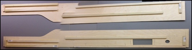
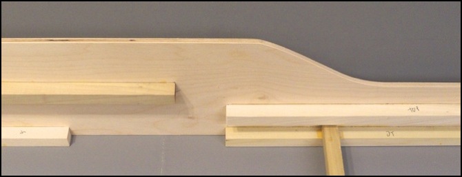
Sides with bracing glued in
The photo above shows the two sides with the bracing glued in. Please forgive the badly-stitched panorama; PE couldn’t cope with my inability to keep the camera in the same orientation when holding it up high. The upper braces (nearest the curved side) will support the insulation foam used as the scenic base. The lower ones will have “feet” attached so the assembly can stand on furniture (a table or similar) without scuffing. Several cross-braces, as well as the two end-caps, will hold the sides exactly 12” apart.
The cut-outs is for the control panel, an aluminum lid from a Radio Shack 270-1803 project box, 5” x 2.5” with pre-drilled holes for screws in the corners. The panel will be screwed through the sides and into the dowels. The only controls on the panel will be a light switch and the Arduino controls (run, emergency stop, and the two max-speed potentiometers). The circular hole is for wires to/from the Arduino, which will be externally mounted.
You’ll note that the upper supports are different distances from the top on the two ends. I’m using 1” (2.5 cm) thick insulation foam on the lowered end, for size reasons. However this foam only comes in 24” lengths, so on the upper section (which is around 40” (102 cm) long, I’m using 2” (5 cm) thick foam, to avoid having a seam. I didn’t need to buy a whole 4’ length of the thick foam, as I still have some scraps left over from the original construction of Sumida Crossing. Eventually the foam will be glued to the upper supports, but initially I’ll just rest it in place, to allow removal for scenery work.
The next step was to glue the sides together. To make the corners square and solid, I used the 5/8” square dowels to make corner braces, first gluing them to the sides and letting that set overnight, then gluing both end-caps to both the sides and the braces and clamping both parts securely until the glue set. This gave me a good right-angle corner, and a very strong bond. I used yellow carpenter’s wood glue for this, as it is not water-soluble once it dries and it creates a very strong bond on porous materials such as wood.
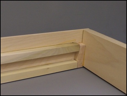
Front corner - the end-cap glues to both side and brace
I also put in three cross-braces, which glued not to the sides, but to the square dowels running along the sides. These were cut slightly shorter than 12”, then clamped in positions that held the sides exactly 12” apart (well, mostly, there was one that got a bit wider before the glue dried somehow). These are really only there to hold the sides a constant distance apart, to create a more rigid structure. But the two end ones are also useful as handles for picking the assembly up by during construction.
Side showing two upper supports at different levels, plus lower-front cross-brace
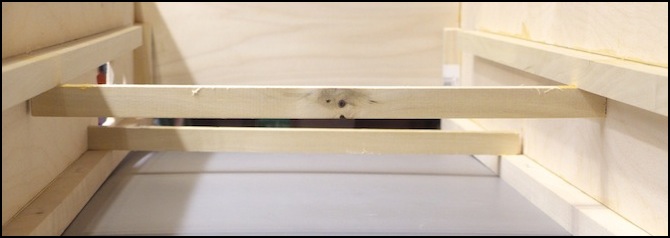
View from low end showing middle and rear cross-braces
Glued, the assembly is quite rigid, and yet surprisingly light. At the back on one side are the cut-outs for the control panel and the Arduino wiring. The Arduino itself will mount in a small box on the outside, where it is accessible for connecting the USB cable to program or debug it.
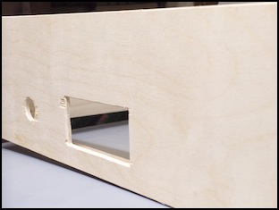
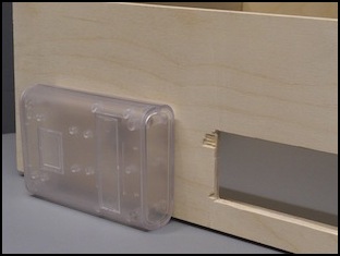
Cut-outs, with planned Arduino box (it expands to hold an Arduino with multiple shields)
And yeah, I’ve yet to master the art of cutting plywood without fracturing it. I probably need a new blade in the saw. Well, that will mostly be hidden under the control panel.
Painting
I originally planned to prime them with my usual gray paint on the outside and partway down on the inside top, and then paint them in the same bright green I used for the Sumida Crossing fascia. After priming, I changed my mind and bought a different color paint for the outside, as the green just seemed to be too bright for this application. Instead I used a medium red-brown, Glidden “Sweet Tea” interior latex in their “satin” finish (I have to wonder who thought this looked like sweet tea; it seems too dark for that).
The primer I used is the same Glidden Gray latex primer I’ve been using on all of my projects. It makes a good base for dark colors, and it’s also a nice color in its own right where I simply need to seal wood, rather than fully painting it. Unfortunately Glidden seems to have stopped making it. I have enough for several more layout tables, but eventually I’m going to have to find a replacement for future projects.
This assembly has now been painted. First two coats of primer went on and dried for 24 hours. Then two color coats went on. I did each side’s color separately and let it dry for a day before doing the other side. Primer will dry enough in a couple of hours that I could flip it over and do the other side. Color takes longer to dry. It will actually remain tacky for some time, so when I did flip it, I used some support “triangles” to keep the painted side up off the table while I painted the other side.
Painted, it then needed to sit relatively undisturbed for several weeks for the paint to fully cure (latex paints take about 30 days to cure). Once that happens, it is relatively immune to scuffs and marking from casual handling. One reason I choose the “satin” finish was to get the most robust finish I could without going to a hard, glossy, shine. But until the paint fully cures (the stabilizers evaporate and the pigment and binder fuse chemically into a hard shell), the finish is easily damaged, so it is important to take care while handling it.
Painting done, cutting the insulation foam to fit came next. I do this with a hand saw for long, straight, cuts, first marking the line I want to follow. This is dusty work, and I kept my shop vac running while I cut. It has a HEPA filter on its exhaust so it doesn’t just blow the dust around. Once cut, I test fit, and then filed the foam down to fit (I deliberately cut it a bit on the wide side), which generates a lot more dust. Finally it was done, and you can see the results at the top of the page.
Insulation Foam Ground
The “ground level” on this, really two ground levels, is pretty basic: just two flat sheets of extruded polystyrene insulation foam. Since I’m modeling an urban environment, I can get away with making this flat, although I may carve in some kind of drainage channel or small streambed, just to add some variation. I’m using 1” (2.5 cm) foam for the short “urban” end, where space is tight, and 2” (5 cm) foam for the long upper part, because I have some and because it will be stronger for a piece over three feet (1 m) long. This also allows me to cave in some detail without affecting the structural integrity of the foam.
The foam will initially be left loose for ease of removal for painting and scenery work. Ultimately it will be glued to the lengthwise square dowels supporting it (I expect to use Gorilla Glue for that, as it’s all I could find that would bond wood to styrene permanently.
Controls and Wiring
The controls for the Arduino mount on a simple sheet of thin aluminum, easily drilled for them, that’s screwed into the side of the layout. These will have wires going to a set of screw terminals inside, from which I’ll run wires to the Arduino pins, allowing me to work on each without disrupting the other. The controls are more fully described on the Tram Controller pages, but there is basically two throttle potentiometers, a run/park switch, an “on”/“emergency stop” switch, and a lighting control switch (which will power both building lights and the IR LEDs used for the sensors.
A power strip will be screwed to the outside, and the several “wall wart” power supplies connected to it. Then the layout can be unplugged with one cord for transportation. This won’t be attached until later in the project, well after the paint is cured.
Wiring from the arduino will be short lengths going to terminal strips inside the support structure. From there, wires will run to other terminal strips directly below track feeders, signal masts, and LED/phototransistor sets. Again so I can work on anything individually without affecting other parts of the layout.
Finally, there will be a 12V supply to where the buildings go, for interior lighting. Exactly how this will be done is still TBD, but I expect to make use of the copper-tape and “wire glue” method I used for the expressway, because that’s the same method I plan to use for the Urban and Village building wiring on the main layout, and this project is in part a proof-of-concept trial of those plans.
