


Building A LOLbooster
Note: this describes work done in January 2011. The kit described is no longer for sale.
Note: as of December 2014 Railstars, the company Don created to sell this kit and other products, is out of business. I’ve left this page here, since it was an interesting kit to build.
I built a do-it-yourself kit to make a DCC booster, called a LOLbooster. I’m something of a novice at electronic kit assembly, despite prior experience with a soldering iron for layout work (track feeders and DCC decoder installs). I haven’t done PCB kit assembly in a very long time, and not much then. So this was a bit of a learning experience for me, but overall a fun one, even if it did have its hair-tearing moments.
Disclaimer: I don’t have any financial interest in the LOLbooster project, but I did get this kit for free in thanks for my interest and feedback during its development. This isn’t intended to be a formal product review, just a record of my experiences.
Boosters
In DCC, there are four main subsystems that work together:
Throttle -> Command Station -> Booster (aka Power Station) -> Decoder
The throttle is the part a human uses, typically with a number of buttons and knobs to set speed, direction, and function state. The Command Station takes input from the throttle (there’s no standard for that, and a number of proprietary systems, like Digitrax’s Loconet, are used) and outputs DCC commands as per NMRA Recommended Practice RP-9.1.2 DCC Power Station Interface. The booster (which is often incorporated in the same box as the command station) takes that signal and modulates it onto a high-current power supply suitable for running trains, which is connected to the track. And the decoder sits on a train, and passes power to the motor and function outputs in accordance with the commands received.
Boosters are typically around 2-5 Amps (some are up to 10 Amps), and can run 10 - 50 typical N-scale trains without sound. If you need more, you can connect up additional boosters. I’d originally thought I was going to need a second booster in addition to my command station, but later testing gave me the numbers above, which suggested I wouldn’t. However, it can’t hurt to have an extra.
A typical booster costs around $150 or more, but these often have unnecessary features. If all you really need is a stripped-down booster than can feed several track segments, it would be nice if there were cheaper options. And a few people have designed circuits to let you build your own. Don Goodman-Wilson, whom I know through the JNS Forum, is one of those people, and his booster, called LOLBooster, is documented on his Railstars website.
LOLBooster is just a booster. You can’t hook up a throttle to it; it needs to be connected to an existing command station. But if you know which end of a soldering iron to hold, you can make one for about $75 for parts and a circuit board from Don (see his site for details). You’ll need to add the power supply yourself, which can often be recycled from an old laptop computer wall-wart (you need one that puts out a suitable DC voltage, 16-18 V DC for N-scale (even 15V will work, but it’s right on the edge), or 18-22 V DC for HO, at a suitable wattage, about 45W minimum for N-scale, and 54W for HO). Higher wattage won’t hurt, but keep an eye on the voltage spec (and it must be DC), and don’t use a lower wattage supply. It’s good not to use too high a voltage either, as this makes the voltage regulator chip run hotter (and it’s already quite hot under heavy load).
As of the Rev. B circuit board, a 15V DC supply will work better for 12V N-scale use, and is recommended.
Round 1 - December 2010
I’d been following Don’s work, and commenting on it. While I don’t really need a booster right now, I need some practice working with electronics and I can probably find a use for a second booster eventually, so when Don offered me one, I said “sure!”. Then I just needed to put it together. This turned out fairly easy, although not without incident. But if I can do this, probably pretty much anyone can.
This also turned into more of an experiment than either of us had originally planned, as some odd behavior uncovered during testing led Don to think about revisions to the design, and some testing was done to support that. I should note that the Rev. A design works just fine, with the caveat that it has some issues detecting shorts, but my Zephyr is also less good at that than I’d expected it to be.
If you haven’t done any soldering before, I suggest investing in a cheap kit to practice with before assembling something like this. It’s easy enough to make mistakes, and why risk a $75 kit on a beginner’s mistake. That said, I haven’t had much experience with through-hole kits (like maybe one, twenty-plus years ago) although I have done a bunch of other soldering since, and I put this together. Mistakes were made as you’ll see below, but soldering badly wasn’t really one of them, I think. Working slowly and carefully, and thinking things through in advance, were my recipe for success.
Note: Don says this can be done in “30 minutes to an hour”, and maybe that’s true for someone with a fair bit of experience. My first board took several hours over two nights to assemble, as I was working carefully and double-checking both the instructions and the finished assembly as I went.
Parts
I won’t go into the full parts list here, as that’s well documented in the instructions (link no longer valid, removed), but it comes with a number of chips that are sensitive to electrostatic discharge, so the usual precautions against ESD need to be taken. The white backdrop you see in all the photos is a grounded ESD work mat, and I wear a grounded wrist strap when working with the chips. You don’t need the mat if you’re careful, but a wrist strap is a really good idea and you can get them at Radio Shack for a few bucks.
The hard work of laying out the circuit board has been done (although you can make your own if you really want to be cheap, assuming you know how).
Note: the photos here are also in the LOLbooster photo album, in case you want to see larger versions.
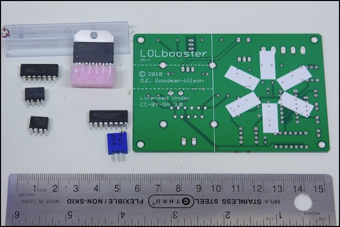
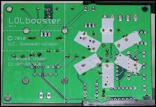
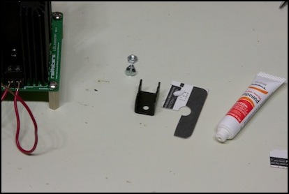
LOLbooster circuit board and some of the parts. It’s quite small.
The Rev. A circuit board I used (above) has a slight problem: the logo was printed over the through holes for some of the components, meaning those weren’t tinned and no metal is exposed. You can expose the bare copper by scraping off the silk-screened printing with a sharp Xacto knife, but that’s hard to do, and once exposed you need to solder to it before the copper oxidizes. I’m told this will be fixed in the Rev. B circuit boards, which will also have a slightly-modified circuit design.
The problem with scraping is that “printing” on PCBs is actually done using the same epoxy used to provide insulation over the underlying copper (all that light green stuff is insulation), so it’s easy to expose the copper ground plane or traces adjacent to a hole when trying to expose the hole itself. Additionally, a similar epoxy is used to hold multi-layer boards together so you can’t use solvents to remove the printing, as this would also expose the copper, and might damage the board itself. Scrape I did, and with predictably bad results at first:
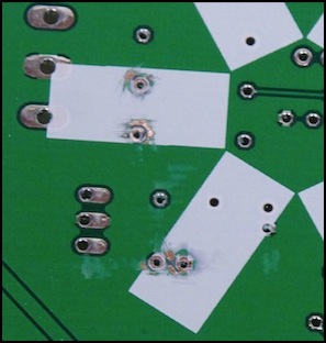
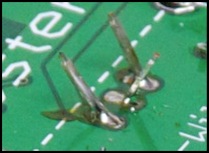
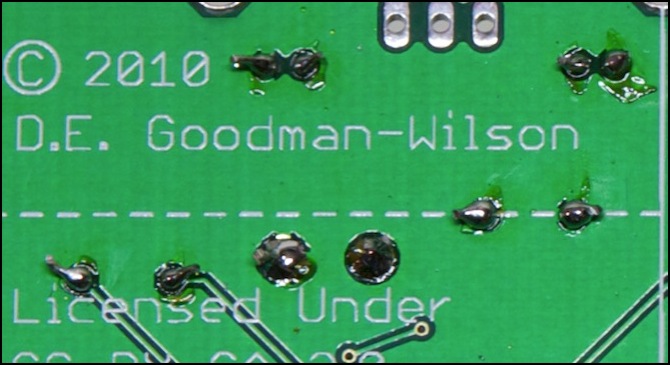
Exposed ground plane
That bright, shiny, metal outside the circle around the two upper holes isn’t part of the hole, it’s the ground plane, or if you’re really unlucky it’s one of the traces that isn’t at ground. Soldering to the board like this is pretty nearly guaranteed to create a short. With a bit more care, and some practice, my later holes were better but I still made a couple of mistakes. The trick is to use the point of the blade, and scrape along the raised bit just around the hole (with the tip slightly in the hole to start, then moving out as you expose more copper). Don’t let the blade get parallel to the board, or you’ll likely scrape something you don’t want to.
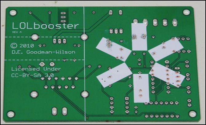
Circuit board with printing (and some insulation) removed
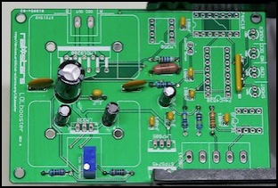
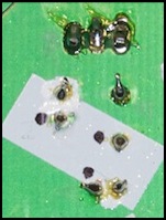
That wasn’t good, so I hit on the idea of using some model paint to cover the parts that should have been covered. First I used my multimeter to verify which holes were normally connected to ground (the black dots in the lower photo are next to grounded holes). These I didn’t need to worry about (well, unless the adjacent copper wasn’t also at ground, something I didn’t think to check then). Then I carefully applied paint around others except at the edge of the hole itself (which is what I’d wanted scraped clear). More testing with a multi-meter followed the paint drying to make sure all was good.
This seemed to have worked, although I noticed the paint blistering when I was soldering (it’s not heat-proof). However, I didn’t have any shorts, and that’s what matters.
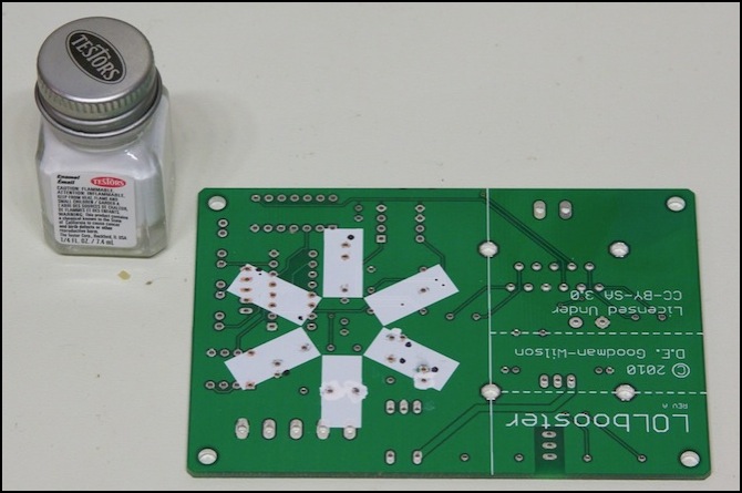
Circuit board with exposed ground covered with enamel paint
More Parts
The individual parts are mostly well marked, and pretty easy to tell apart based on shape or number of pins. In some cases the print was small enough, or faded enough, that I had to use a magnifying glass to check. The only potentially troublesome ones are the two 8-pin chips (LM358 and SFH6731), which had rather faint printing, and the small ceramic capacitors (which are marked, but not always well). Ceramic caps are marked with three-digit numbers, with the third representing the number of zeros to insert after the first two digits to get the capacitance in picofarads (1 nF is 1,000 pF, or “3”; 1 μF is 1,000,000 pF or “6”).
Something to be aware of is that labels for packages containing capacitors may be printed by systems that lack Greek letters. In such cases “μF” is written “MFD” (which looks like lit ought to mean “milli”, but it really does mean “micro”).
Also note that the SFH6731 doesn’t have a notch at one end, just a very faint indented circle in one corner (that’s the “notch” end for when you go to install it).
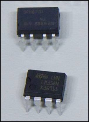
The two 8-pin chips: SFM6731 (top) and LM358 (bottom)
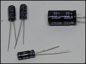
Electrolytic Capacitors, clearly marked.
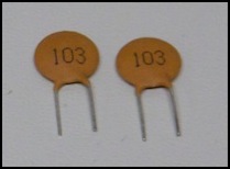
Ceramic Capacitors: 10 nF (“103” = 10 x 1,000 pF)
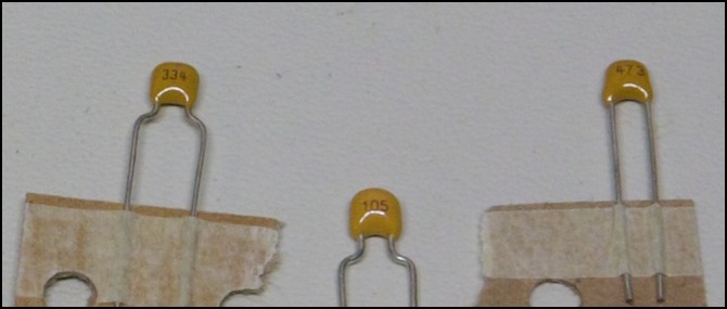
More ceramic capacitors (L to R): 330 nF “334” (aka 0.33 μF), 1,000 nF “105” (aka 1 μF), and 47 nF “473”
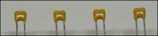
Four 100nF Ceramic Capacitors. These are the hard ones as they had two rows of numbers front and rear, and only one of those rows read “104” (and it was really hard to read). As long as you don’t separate them from the paper tape they come on, the fact that there are four is a good reminder of which these are.
Tools
Good tools are needed for any work. In addition to my soldering iron, I also used:
- Small needle-nose pliers for bending leads.
- Hardened-edge cutters for trimming leads.
- IC insertion and removal tools.
- Magnifying glass and flashlight for checking work closely.
- Hobby vise with weighted base and large jaws suitable for small circuit boards.
- A couple of small aluminum clip-on heat sinks for soldering (which I used as clamps).
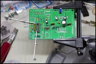
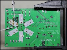
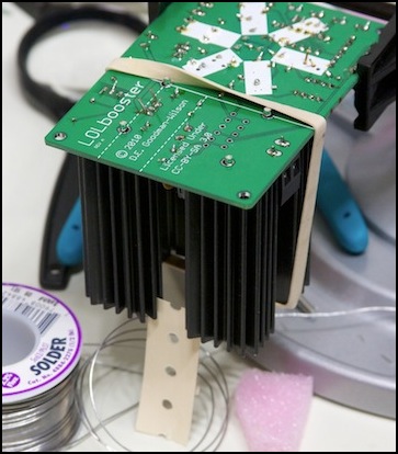
My vise, seen in the picture below, turned out to be just large enough to hold the circuit board (the jaws are notched for this). They do make larger ones for big circuit boards. I’d originally bought this for model-building, but it worked well for its intended purpose too. Mine is a PanaVise Junior (model 201) mounted to a weighted “tray base mount” (model 312).
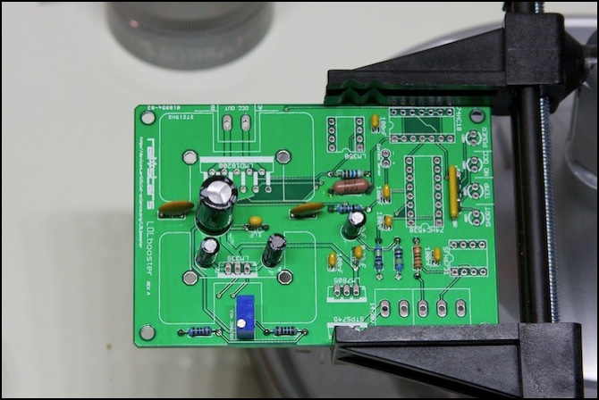
Circuit board clamped in vise (a ball joint lets me quickly flip the board over to work on the back)
Soldering
I don’t consider myself to be very experienced at precision soldering. I understand the theory, and I’ve soldered more track feeders than I can count (and melted more than a few ties in the process), as well as a few wire-in decoders. But circuit boards and components, not so much (and it was a long time ago, and I never did much even then). So there was a bit of trepidation as I prepared to actually attach the components.
Note: avoid the temptation to put your face above the object being soldered. Burning rosin is not something you want to inhale. A small fan to draw air across the object and away from you is helpful.
Basic strategy: Put the components to be soldered in place in several batches, starting with the ones closest to the board (e.g., do all the resistors together). Bend the leads at about a 45° angle so they’ll stay in place when you turn the board over. Suspend the board upside down so the components hang free under it, and don’t have any pressure against them. Let the iron heat to working temperature. Then “tin” the tip (melt some solder onto it and wipe the excess off on a damp sponge, which should give you a shiny silver tip). Let the iron re-heat, then working from the non-component side of the board, touch the tip of the iron to a lead right where it emerges from the board and to the bare metal on the edge of the hole, and touch the tip of the solder (hold it about 3” back) to the opposite side, also touching both lead and board. Wait for the solder to melt (5-10 seconds), then push the solder wire down until you’ve melted enough to fill the hole and a bit more; about two inches assuming you’re using fairly thin solder. Remove the solder, but hold the iron in place for several seconds so the solder flows down into the hole, then remove the iron and don’t touch the board for 10 or 20 seconds (the iron needs to re-heat and the joint you just made needs to cool). Inspect the work to be sure it looks okay, then move on to the next component. When all are done and the board has cooled off a bit, clip the excess leads just above the end of the solder.
And note that the joints will typically look a bit dirty from the rosin, and this can make it look like solder has flowed away from the hole even when it hasn’t. But unless you put way too much solder in, surface tension will hold it close to the lead. If you do manage to connect two leads together you can remove excess solder using a de-soldering braid.
A good solder joint should be shiny and both fill the hole and stick up a bit along the lead, like the one in the front of the photo below. These don’t actually have to be perfect; the back one in this photo is a little dull, and the middle one doesn’t have quite enough solder on it, but all three work reliably.
Solder joints before trimming leads
Things actually went fairly well. I worked in stages, as the instructions recommend, placing all the resistors on the board, then soldering them. I did a bit of checking with my ohmmeter after that, finding points I could touch the board traces to measure through each resistor. That let me verify that all my solder joints were good ones (a bad one would have significantly higher resistance). After that, I did the same with the capacitors (this time doing the ceramic ones first, and after they were soldered applying the electrolytic capacitors) although I had no way to test those. I nearly forgot to check the polarity on the electrolytics, but I was working slowly and checking the instructions before I attached each set of components, and that reminded me.
That was good for two hours of work (slow and cautious, that’s me), then I stopped for the night. Part of me really wanted to finish. But the sensible part noticed that it was late and I was getting tired.
The board after attaching resistors and capacitors
Not pretty (and I don’t like the lack of shine on the one at the lower left), but they appear to be good joints.
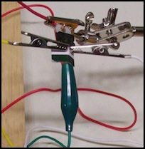
The next day, I finished up the soldering. This included attaching the sockets for the chips. This needed a bit of finesse, as the pins are too short to bend, so the socket kept falling out. I finally hit on using a couple of aluminum clamps used to protect delicate components when soldering to their leads, using them as simple clamps to hold the socket in place (this only works if the socket is near the edge of the board).
Socket clamped to board with two aluminum clips.
The other problematic parts were the two large heat-sinks. The right solution would be to attach the chip to the sink after spreading heat-sink paste appropriately, then solder both the chip and the heat sink to the board for strength (otherwise the weight of the heat sink may flex the chip leads and damage their solder joints). But I want to run a couple of tests that require removing the heat sink, so for now I’m soldering the chips, but not the heat sinks, and using caution moving the board around. I’m also not using heat-sink compound yet, but as I don’t plan to run the board for long at any given time, and I’m woking in a cold basement, the poorer cooling provided is not likely to be an issue.
So I attached the chips to their heat sinks to ensure each was the right distance above the board when soldered, clamped the heat-sinks in place with a rubber band (and a couple of bits of cardboard between them to keep the band from pulling them towards each other, and soldered the chips in.
A simple clamp: cardboard and rubber-band
With all the soldering done, I installed the four integrated circuits in their sockets. I could have done this sooner, but why risk damaging the chip somehow? Installing a chip in a socket isn’t hard, however despite lots of experience (I used to work with equipment that needed chips swapped for software upgrades) I managed to bend a couple of pins, and somehow installed at least one chip in such a way that it caused problems later. This is a place where caution is really called for, and I rushed a bit and paid for it later.
The thing about ICs is that their pins angle outward, so they’ll fit snugly into the socket. You can install these by hand, without any tools, very carefully (a grounded wrist-strap is essential). The method I learned long ago is described here. To summarize: place one side just barely in the socket, push the chip sideways to compress the pins until the other side lines up with the holes, then straighten it out and gently press down, making sure you don’t miss a hole and bend any pins. Once all pins are firmly in the socket, press on the top of the chip case with a fingertip to seat it all the way down. This method works better if you bend the pins in just a bit with your fingers first.
As noted, I managed to do this wrong. A chip insertion tool is cheap, and does this much better (put the chip in the end of the tool, which compresses the legs, set the whole assembly down on the socket so the tips of the legs are above the correct holes, push the plunger down to set the chip into the socket, then removed the tool and use your fingertip to set the chip all the way down as described above).
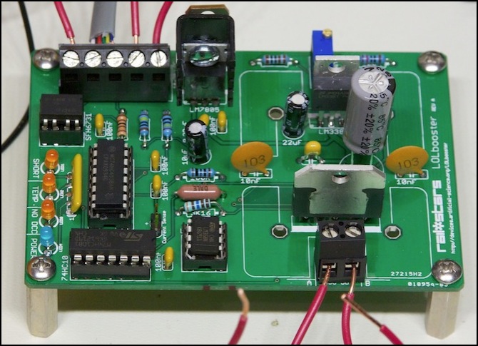
When all was said and done, I had a finished LOLbooster, or so I thought:
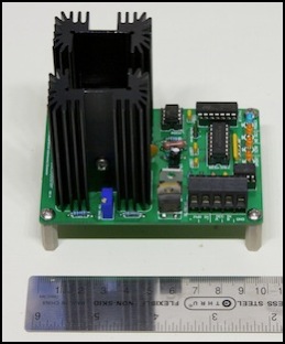
LOLbooster: done?
Debugging the Board
Life is never that simple. I hooked up my Zephyr as the control station (DCC inputs and Ground) a +15VDC power supply (DC+, DC-), turned it on...and nothing happened. No warning lights, no voltage on the DCC output pins, no smoke or odd smells.
I’ll cut to the chase: the problem was something to do with the ICs not being properly inserted into their sockets, perhaps a bent pin. I eventually removed and reinserted the socketed chips, and the board started working. I’ll summarize the initial tests in case they’re helpful to others, but if you’re not interested you can skip to the next section.
After a bit of fruitless testing that wasn’t very well directed I asked Don for help. Some more focused testing followed, that showed the LM338 was outputting 13.6 VDC (about what was expected) and this was reaching the input (pin 1) of the LM7805, but that the output (pin 3) was at 0 V instead of +5V. And the solder joints all looked good. So, bad chip, right?
With much effort I removed the LM7805, picking up a replacement at Radio Shack (it’s a fairly common chip). Taking the old one off was mostly an effort of patience. I cut the three pins to remove the chip. This was made easier by the fact that I could remove the big heat-sink on the LM338 next to it since I hadn’t soldered that down. Then using a solder wick, I removed as much solder as I could from each side of the board. Then I heated the pin from one side while gripping the stub on the other side, and gently flexed and turned it until it was loose and could be pulled out. After letting the solder cool, I opened up the holes with a very small drill held in a pin vise until they were large enough for a new LM7805, but I didn’t install it just yet.
Note: removing components from a PCB is a bit tricky. While it worked for me this time, as you’ll see below a later attempt removed the electrical contact altogether, breaking the board.
Next, I took a +5V power supply I happen to have and tried touching it to the pad where the +5 output of the old chip had been (red wire below):
LM7805 removed, +15 (white/copper wires) and +5 (red/black) connected.
What’s interesting is that the power light on my +5V supply went out the moment I touched the pad, and came back on when removed. More thought and discussion, and I opened up the +5V supply (which I’d built a long time ago). A check with my IR thermometer showed its LM7805 (yes, it has the same chip; I said it was common and available at Radio Shack) was heating rapidly (from 68°F to 125°F in about 10 seconds, despite a heat sink). The supply wasn’t turning off: it was connected to a not-quite-dead-short, and trying and failing to provide much more than its 1 Amp rating into the circuit. That kept the output voltage very low, which kept the power light (which on my old supply is just a LED and resistor across the output terminals) from lighting
I’d previously checked the resistance between the LM7805 pads and ground, and one of the two had been much lower than the other, which I thought was significant. But I think I was measuring the LM7805 itself, or some other circuit element. For a while I thought I might have shorted to the ground plane where I’d accidentally exposed copper before, but lots of checking resistance to ground (which generally gave me large numbers rather than the 0.1 Ohm or less of a short) seemed to rule that out. Another possible idea was that I had defective capacitors (which should be heating if they’re shorting).
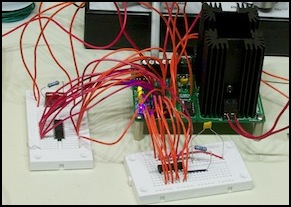
I then hooked up what was left of the old chip to my 15V supply, with a mess of alligator clips and some cardboard for insulation, as well as a couple of spare 100nF capacitors from my parts drawer, and sure enough it worked fine (regrettably with the pins maimed, it’s not going back in). The photo below shows it outputting +5.026 VDC when fed with +15VDC.
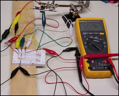
Rube Goldberg’s breadboard (chip top center in clamp, caps on left side of white board)
Note: in the following photos, the black dots are next to contact points that are normally connected to ground (I measured them before adding components and marked them with a sharpie marker).
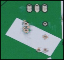
Board backside, before and after adding components
Along about here I took the socketed chips out of the board, to protect them during further testing. Unfortunately I couldn’t re-create the problem without them, so I put them back in (this time using an insertion tool as described above). And to my surprise, the problem had gone away. I’m fairly sure the culprit was a pin on one that had bent, rather than going into the socket, as one pin wasn’t quite straight when I went to insert them the second time.
Final Assembly: Heat Sinks
I still hadn’t soldered in the big heat sinks, so I needed to be careful when handling the board, keeping them vertical (and upright unless I was working on the underside of the board) to minimize stress on the attached chips. But I did finally add the heat-sink compound (a bit more on how useful this is in the testing section below).
Heat sink compound (also known as “thermal paste” is used to fill the microscopic surface irregularities in the heat sink and the metal part of the chip it’s touching. Without it there is air in those gaps, and air is an excellent insulator, which reduces the effectiveness of the heat sink. However, thermal paste isn’t as good a conductor as metal (in fact, it’s actually pretty poor, just better than air), so you want the metal to touch where it can. A very thin layer of paste is recommended, typically a “grain of rice”-sized amount for a computer CPU. The chips we’re heat-sinking are smaller than that.
LM7805 heat sink with a “grain of rice” of heat sink compound (use about half on this sink)
I applied this to the metal part of the chip where it will touch the heat sink, spreading it with a small piece of cardboard cut from the packaging the paste came in. I used ordinary Radio Shack 276-1372 “Heat Sink Compound”. Although you can also get metal-based pastes such as Arctic Silver, there really is little benefit to paying extra for such formulas (see this site for a nice example of the differences). Once applied, I used the cardboard to scrape it into a very thin layer.
You can also use your finger, or a latex glove. However fingers can contaminate the compound with oils, and if you use gloves they need to be the non-powdered kind to avoid contaminating it with powder. A razor blade or credit card edge also work.
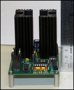
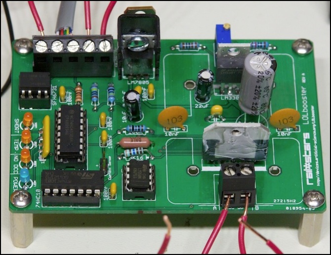
With the paste spread, I attached the heat sink with the provided screw, nut and lock-washer. Then I did the second one. After initial testing showed the LM7805 running a bit hot, I also added a heat sink to it.
LM7805 with heat sink attached (center rear)
Heat sink compound spread a bit thick on LMD18200 (it needs to be scraped thinner)
Testing
Once the board was apparently working (well, the little blue power light came on; that’s a good sign) I needed to run some tests. Some of these were to confirm basic function, others were things Don requested for his own information. I won’t bother to summarize all of them, but these are the important ones:
Note: all tests were done with my Zephyr’s RailSync lines (outermost two wires on the Loconet cable) connected to the DCC inputs and the Zephyr powered up. I also used a 15 VDC power supply for the LOLbooster itself; a reasonable size for N-scale use.
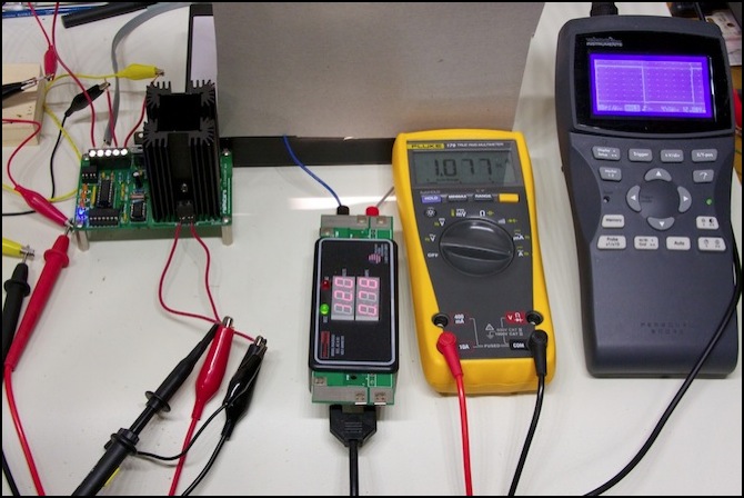
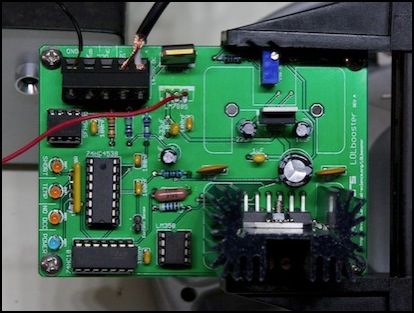
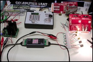
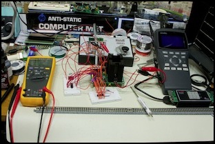
Test Rig (multimeter used as Ammeter on input power, RRampMeter (with bulb) used as output load and meter, oscilloscope used to check DCC output shape)
Test 1: burn-in
Connect the power and Zephyr, connect my RRampMeter to the output, with a 12V, 18W automobile lamp across the “track” side of that (this is my “load” tester I’ve used elsewhere). The LOLbooster turns out to be sensitive to the inrush current of a bulb and connecting one once it’s powered on will trip the “short” detector, but powering up with one connected works fine.
I powered up, noting that the RRampMeter was reporting 12.0 volts on the rails (sheer coincidence), and let it run for 20 minutes with the bulb as load, checking the temperature on all eight of the ICs every 5 minutes using a hand-held IR thermometer. The room I was testing in was a chilly 60°F (about 16°C). Most chips were only a few degrees warmer, and never warmed up. The two big heat-sinked chips did get warmer, with the LM338 climbing to 72°F (22°C) fairly quickly and the LMD18200 climbing to 82°F (about 28°C) over 15 minutes, then stabilizing. The two large socketed ICs (the 74HC10 and 74HC4538) both went to about 68°F - 70°F fairly quickly, but stabilized there.
If the output voltage of the booster isn’t quite what you want, turn the screw on the “voltage adj.” pot (next to the LM338 heat-sink) to adjust it. Note that this pot has a very limited lifespan measured in turns; get it set to a value you like, and then don’t touch it.
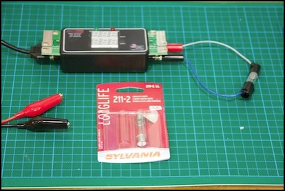
Simple Load Tester (RRampMeter and 18W bulb)
Test 2: short circuit protection
With the system as above, except for the RRampMeter and bulb, connect a short wire to each DCC output, then power up and touch the ends together and hold them. What should happen here is that the “short” LED lights and the power to the track is cut off. That’s not what I saw.
2a) Testing as above, the “short” LED did not immediately light; instead eventually the “temp” LED will come on, holding for another 5 seconds would cause the “short” LED to come on, and the output to shut down. Release the wires and wait 5 seconds, and the failure will clear. Doing it a second time, and this time it will immediately light the “short” LED.
2b) Now power everything off, connect up a load (I used the RRampMeter and bulb again) and repeat. This time a short will be detected instantly.
Note: if you connect the bulb after the booster is powered up, it will trip the short warning because a cold lightbulb draws a very large current when it warms up. If this happens while the booster itself is starting up, not enough power is available to trip the warning, and the bulb warms up slowly. But if the booster is all powered up, it tries to feed the bulb the power it needs instantly, and that’s too much for it.
The problem here appears to be that I was testing too soon after powering up the booster. If you wait a few seconds, shorts are more reliably detected. That may not be the whole of the problem, but things did improve after waiting.
Note: this behavior isn’t strictly desirable, and Don is making changes to the Rev. B board to delay power-up until the board is ready to detect shorts.
2c) I did a more realistic test, connecting the DCC output of the booster to some track (without trains), powering it up, and placing a quarter across the rails. The quarter test can fail, if the voltage loss in the rails is too high (it’s a good test for inadequate or too few feeders; if a quarter shorting the tracks doesn’t shut down your DCC system, your wiring is bad). I had used a multi-section length of Unitrack from a box of previously-used track, with an extra-long (about four feet) Kato 24ga feeder wire for this test, and that was apparently enough to cause some problems. Even trimming it down to two feet of track was a bit problematic.
With the LOLbooster, the first time I tried this after powering on the booster the “temp” warning LED came on after 5 seconds, and then the “short” LED lit after about 20. The second attempt after powering up the booster worked, and it always detected the short. This may have been another “need to wait longer before shorts can be detected” problem.
Oddly, testing with my Zephyr powering the track also failed to detect the short (the quarter started “singing” when placed on the rails, and after about 30 seconds the Zephyr shut down, apparently from high-temperature). That’s really surprising, as the quarter-test is pretty universal, and the Zephyr normally responds correctly to it. I suspect my test track has a high enough resistance (due to old and bent/dirty unijoiners and the long feeder wires) that it causes a slow ramp-up rather than a quick short. And this is part of the problem seen with the LOLbooster. I also have a very old Zephyr, from when they first came out, and perhaps those had some design problems.
It’s not clear that’s the whole story, and this is an area Don’s continuing to look into.
Test 3: Voltage Adjustment
Using the RRampMeter with the light bulb as a load, I measured 12.0 volts with my 15 V supply. I then tried to adjust this using the adjustment screw on the “voltage adj.” resistor tucked in above the LM338. What I found was that 12.0 was the maximum, but I could adjust it down to about 10.9 V. I replaced the supply with a 16V one, and now the peak output was 13.0, and I could adjust it down to 12.0 (and perhaps further: I didn’t try). I liked that better, but I tried again with an 18V supply, which didn’t change it from the adjusted 12.0 I had.
My conclusion is that a 15V supply would work for N-scale, but it’s right on the edge, and that a 16V supply has a bit more headroom, so I’m going to use 16V DC as my minimum instead. Anything from 15-18V DC should work. Note that the higher you go, the hotter the LM338 will run, dumping excess heat to drop the voltage, so for a 12V output, a 16V power supply is probably ideal.
Note: as described below, the Rev. B board has been redesigned, and 15V is now the recommended size.
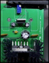
Adjustment screw (blue box, top)
I left the booster configured to provide 12.0 volts DCC into an unloaded circuit.
Test 4: Hook up track, run a train
I did. My little DE10 happily ran back and forth on the test track, responding to the Zephyr throttle fed through the LOLbooster. Success.
Test 5: Load Testing
I’d planned to stress-test the booster using a bunch of lightbulbs like the one I use with my RRampMeter. This would allow me to run for extended periods at multiples of 0.8 Amps. The problem is that if I connect the bulb up once the booster is running, the inrush current causes a short to be detected, and when the system restarts, it detects it again: result, the booster shuts down and stays down. I also had problems getting wires soldered to the bulbs (I kept getting cold joints with excessive resistance, which kept the bulbs from working properly).
I eventually built a test load with six small bulbs which didn’t short the booster if they were attached at power up, but didn’t provide enough load either. I replaced two of the bulbs with larger ones, and that got me to a 2.5A load without tripping the booster. The bulbs were wired in parallel, so each gets full voltage and their currents are additive.
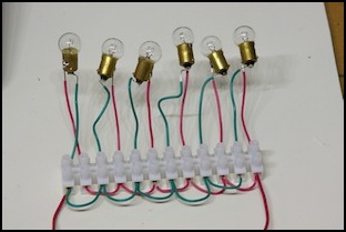
Test Load #1 (left) and #2 (right, in use)
All of the following tests were run using a 16V DC power supply, with the booster set to deliver a 12.0V DCC output with no load. And all were tested with a 2.5A load that caused the output voltage to drop to between 10.3V DCC and 10.9V DCC. Ambient temperature for all tests was 69°F - 70°F (~21°C).
Note: the same load causes my Digitrax DCS100 (calibrated for 12.0V with no load also) to drop its output to 10.8V DCC, so I don’t consider this a problem.
5a) Load Test w/o LM338 Heat Sink
I forgot to attach the LM338 heat sink, which I’d removed to work on one of the capacitors earlier, before starting my test. The booster shut down almost immediately. Okay, heat sinks are important. Got that.
5b) Heat Sink, no thermal compound, no LM7805 heat sink
I ran a test with the two big heat sinks attached. The temperature got to 147°F (64°C) on the LM338, 132°F (56°C) on the LMD18200, and something around 115°F - 120°F (46 - 49°C) on the LM7805 (it was hard to measure since it was right next to the big heat sink). Then it shut down after 27.5 minutes with no lights lit. My suspicion was that the 7805 overheated, as it is what powers the LEDs.
5c) Heat Sink on all three, with thermal compound
This worked better. I ran the test for one hour with no shutdown. Temperatures stabilized at 144°F (62°C) on the LM338, 136°F (58°C) on the LMD18200, and something around 90°F - 100°F (32 - 38°C) on the LM7805. The heat sink compound didn’t seem to make much difference, but perhaps I’d put it on unevenly or too thick. It also needs some time to settle in. So I turned the booster off, and waiting a day to try a longer test.
5d) Heat Sink Extended Test
I ran the same test as (5c) again, for a period of four hours before I shut it off. Temperatures stabilized at 154°F on the LM338, 140°F on the LMD18200, and something around 95°F - 110°F (35 - 43°C) on the LM7805. The higher temperatures tell me the heat sink compound was doing a better job conducting heat to the heat sink, away from this chip.
Despite the problems, the booster basically works. I’m going to be running more tests, and I’ll post to this page if there’s any interesting news to report. But I expect that at least for now, there’s nothing more to say. You (and even I) really can build a working booster in just a couple of evenings. How cool is that?
Round 2 - March 2011
The original tests were done over Christmas break, 2010, and into early January of 2011, which is when the material above was written. Unfortunately, this ended prematurely when, in the course of removing some components to test an alternate circuit design for Don, I broke the board. We were both busy, so this ended work for a few months.
Note: What I did was in the course of de-soldering a component’s leads, I apparently pulled up the metal contact plated on the board because I hadn’t fully separated the lead from it before pulling it up. This left no metal around the hole to solder to, and thus the new component couldn’t be installed. The moral of the story is to work carefully and not get impatient when removing components (or better yet, to avoid having to do so at all).
Don sent me a new board, and I bought some new components for it, and I assembled it. This is still a Rev. A board, but the idea was to try some of Don’s planned Rev. B circuits on a break-out board and see how they work.
Rev “A.5” testing
The results were quite gratifying: the booster now takes 6 seconds to power up, but it always reliably detects short circuits, either those in place initially or later ones. It also runs on a 15V power supply (versus the 16V supply I’d used previously) and because it’s wasting less power, it runs cooler too.
Don was satisfied and has gone on to make the RAILbooster, a pre-assembled version of essentially the same circuit. I don’t have one, as I’d already bought my Digitrax system before he began this project (in fact, the LOLbooster I built is gathering dust since I don’t presently have a use for it). But I really like the concept of small boosters you can buy for less than $100 with power supply, and use where you might otherwise install a circuit breaker to provide a local, protected, supply for a yard, expansion section, or whatever.
