


Equipping a Kato "DCC Ready" EMU
I’d installed DCC decoders in HO locomotives, but N-scale EMUs were quite different, and that made my initial attempt an entirely new experience. First, the space is much more constrained, and the cars have windows, which makes an inconspicuous install even more important. Second, the cars are very small, which demands more care and precision. That said, it isn’t really as hard as it may look, although there can be some pitfalls.
If you haven’t already, please read my guidelines for safe handling of electronic components before doing this yourself. Also, always test the train on DC power first, and confirm that the motor works easily in both directions, and that both sets of headlights and taillights work (note that some cab cars have an on/off switch for the lights, check that if there’s a problem.
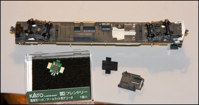
For now, I’ll concentrate on the “easy” one: adding decoders and lighting to a Kato “DCC Friendly” EMU. The decoders used are the EM13 for the motor car, and the FL12 for the cab car head/tail lights. I did not install the FR11 for car lighting, since LEDs aren’t prone to burn out from being left on, and omitting them saved nearly $200 per EMU set. I put “easy” in quotes above, because it turned out to be harder than expected, although I should have realized what I was in for from some of the other installation stories I’d read online (see links at the bottom of the page).
The two cab cars need FL12 decoders to make the head/tail lights come on in the appropriate direction. These are reversible decoders (the orientation controls which end the car is, head or tail; the “head” has its headlights lit when the train is set to “forward” direction). This proved to be incredibly frustrating. I’ll cover that in more detail later.
EM13 Motor Decoder
I started with the motor car, which uses the EM13 decoder to control the motor. This decoder inserts through a hatch in the bottom of the car, and slides between the motor and the brass rails that connect the motor to the wheels for electrical pickup, which ought to be a fairly simple thing to install, and I’m sure Kato thinks it is. My experience wasn’t quite that smooth.
First, to open the hatch, you need to slide it towards one of the wheel sets. The direction is indicated by a small arrow. Grasp the car in one hand (bracing the end you are sliding towards against a soft surface helps) and gently slide the hatch. It sticks a bit, and you may need to apply more pressure than feels safe, but resist the urge to squeeze it or apply pressure towards the car. All it needs is a push from a single fingertip. Once you have it off, you can see the underside has four simple hooks, and the body has four slots. Set the hatch aside, and remember which way you slid it.
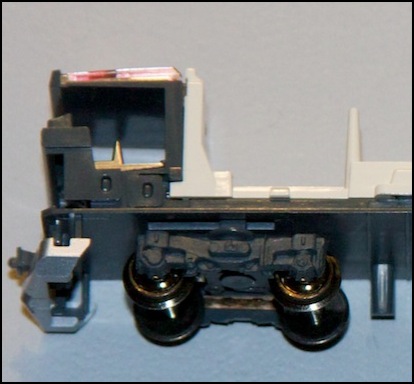
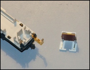
Under the hatch is the motor and two long brass pick-up rails leading to the two trucks (wheel assemblies). Next you need to remove one of the trucks. It’s the one towards which you slid the hatch, and looking at the body it’s the one where there is a decoder-sized recess between the truck and the motor (at the other end, two metal tabs stick up, making it obvious you can’t install the decoder there).
Removing the truck is the hardest part of this, at least for me. It requires more force than I like, and I continue to think I’m doing it wrong and am going to break something. Kato recommends prying with a screwdriver, which to me sounds even worse. My technique is to firmly grasp the car in one hand, and the truck with thumb and forefinger of the other, then tilt the truck away from me and apply force both sideways (towards the side of the car) and away from the car. It will (eventually) snap out of the receptacle on the car body. Moving it around a little may help, but it’s mostly forcing the tab out of the socket on the body that does the trick. The drive shaft between the motor and the truck comes away with the truck (it’s just snapped into the flywheel on the motor, and will slide back in easily later). With the truck off, the recess for the decoder is accessible.
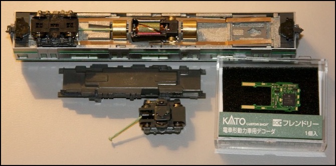
In the above picture, the truck has been removed, and the gap to receive the decoder is visible to the right of the flywheel. The decoder is shown in the orientation in which it will be inserted.
Now you slide the decoder in between the brass rails and the motor. This is one of the tricky parts, for two reasons. First, the decoder has an orientation, and you need to get that right. Second, it doesn’t always make good contact, and you won’t know until much later, but trying to fix that now may cause more problems than it helps. Assume it worked for now, but you may come back to this step later.
Orientation is important, as one side of the decoder has to touch the rails from the trucks (DCC power supply), and the other side has to touch the two round tabs on the sides of the motor (DC power output to motor). On the two forks of the decoder, the side with the long single contact strip should touch the power rails, and the side with the short strips at the ends should touch the motor. Which side is towards you depends on the specific model you are working on (on the EMUs I worked on, the motor side was towards me, but one install I read about was reversed, and this caused me a bit of confusion).
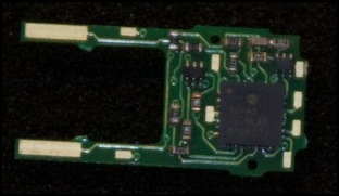
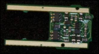
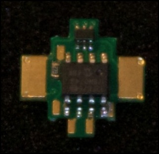
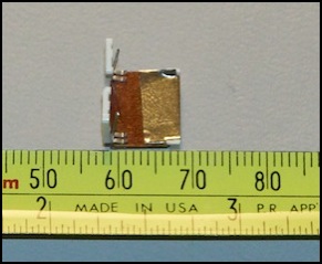
EM13 Decoder: L: Motor Side, R: Pickup Side
These are the two sides of the EM13 decoder. On the left is the side that faces the motor (towards you when looking at the bottom of the car in this E231). Look closely at the large end of the decoder and you will see that the green material bulges slightly at top and bottom. These fit into notches in the gray plastic lining the body, and serve as a good indication of proper positioning. Also, along the two arms are a pair of small green tabs (at the ends of the gold-color contact pad in the left photo). These bump against the gray plastic arch between the motor and right flywheel (if you push the decoder in too far, the arch will bend towards the flywheel as these push against it).
When the decoder is properly inserted, it lays flat in the recess, which allows the cover to lay flat. If the cover doesn’t lay flat, it’s because the decoder is in the wrong place. There are tabs on the cover that fit into gaps when the decoder is properly positioned, and hold it in place laterally, while the cover itself keeps it from moving vertically.
To test the decoder, place the car on the programming track, and try reading CV8, the manufacturer ID (with JMRI, use DecoderPro and start the Service Mode Programmer from the Tools menu, then click “identify decoder”). Since the Kato decoder is actually manufactured by Digitrax, a value of 129 should be read. If the read times out, try again (sometimes the EM13 is hard to read). However, if it can’t be read, the decoder is probably not making good contact with the power rails. In other words, the long contact pads (right photo of decoder above) aren’t resting properly on the brass strips that run under the truck you removed and re-installed.
Note: don’t write into CV8, unless you want to reset the decoder to factory defaults. It’s a read-only CV, but attempting to write 08 to it will reset the decoder to default values, which is useful if you think you’ve made a programming mistake.
If you can’t read from the decoder, before doing anything drastic, check the DCC command station to be sure it’s working (if you have another DCC locomotive that works, try reading its manufacturer ID). Then try sliding the decoder left or right a little, and check the positioning of the rails as much as you can without removing the truck. Reassemble everything (and it’s important that the cover is back on the bottom of the car, as the rails won’t make good contact without its pressure) and try again.
Only if all that fails, take the decoder out, and place a small shim (of something non-conductive, like 0.005 inch plastic, or a layer or two of index card) below the brass rails on each side (make sure they’re not wider than the rails and that they don’t block the gaps where the tabs from the cover fit, about 2 mm wide by about 1 cm long is probably a good size). This should press the rails up into the decoder. But shims too thick may cause the top side of the decoder to pivot down at the far end, away from the the motor contacts.
If it works, don’t program anything yet. Instead, put it on the track and try operating it (it will have address 03 by default).
If the decoder is readable, but the car doesn’t work on the track, try making the control station “forget” the decoder and re-learn it (for some reason this fixed a problem with one of my cars). JMRI is very useful for this, as DecoderPro has a Slot Monitor that can be used to “forget” a decoder (that’s for Digitrax control stations; other systems may or may not have something similar).
Note: if you want to program a 4-digit address on an EM13, it’s possible, but there’s a trick to it. See the Kato DCC Decoders page for details.
FL12 Cab Lighting Decoder
Since the motor car is typically in the middle of the train, the decoder there can’t control head and tail lights on the cab cars. Thus, each cab car needs its own head/tail light decoder. That’s the FL12’s sole purpose.
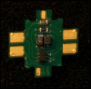
FL12 Decoder: L: Light Side, R: Pickup Side
Installing the FL12 decoders in the two cab cars proved to be quite the experience. First, these decoders can’t be read, even on the programming track, so there’s no way to be sure they’re set correctly short of using them. And when they don’t work, it’s unclear if it’s a programming mistake, poor electrical contact, or perhaps a defective decoder. And in my case, it wasn’t any of these, but operator error.
First, the decoder install. As seen above, the decoder has two sides. On one is a pair of gold contacts on each tab, on the other a single contact on each tab. The E231 cab car is similar to the motor car, in that a pair of power traces run along the bottom of the car, inside the floor. This is the side the two big contact pads (right photo above) should face towards. The four smaller pads face towards you.
The decoder installs through a small removable hatch on the bottom of the car. On some models, there is a plastic spacer inside the hatch that needs to be removed. See the photo above. With the hatch and spacer removed, slide the decoder in underneath the plastic wings (to the right of the larger opening, above. This is fairly hard to do, as the decoder has to be at the right angle to push the power strips away from the wings. Once in, slide the decoder all the way to the right, then replace the hatch cover (but not the spacer).
Note that the decoder can face in one of two directions. In one, the headlights are lit when the throttle is set to “forward”, in the other the tail lights are lit (and, of course, they reverse when the direction is changed). You don’t actually need to know which is which, just do each cab car the opposite of the other, and figure out which is the “front” when you have them on the track. Then place the motor car on the track, facing so that “forward” moves the front cab forwards.
Having done all that, it didn’t work. Repeated attempts to seat it properly didn’t do anything. Resetting the decoder to factory defaults didn’t do anything. Frustratingly, sometimes the headlights would flash briefly when the car was placed on the track, suggesting a loose connection. I tried a different decoder. I tried the other cab car. I began to contemplate trying another hobby.
After giving up and letting it sit for more than a week, I remembered something fairly important: lights are driven by a DCC function output, and DCC functions have an on/off state. What if the default state of the decoder was “off”? The decoder defaults to using F0 for the head/tail lights. Back on the operational track (not the programming track) it went, and F0 was pushed. The lights came on. Aside from feeling like a complete idiot, I was very happy.
With all three decoders installed, I programmed a 4-digit address in each. I had to reset one of the cab cars and do it over, as one of the three variables apparently didn’t get set. But in the end it all worked.
Car Lighting
Kato’s car lighting kit (11-209 or 11-210) is fairly simple to install, although the light controller board doesn’t always make good contact, and may need to be moved around a bit (this seems to be a theme with Kato’s circuit boards, and a surprising weakness on an otherwise very well designed model).
As of late 2011, Kato has a new version of the interior lighting kit that is much improved. This is described on my Kato Interior Lights page. At present this is only available in Japan, but that will change as the boxes are marked for Kato U.S.A. also.
If the interior lights don’t come on, or if they flicker or flash when the train is stationary, the cause is most likely that the lightboard is not making good contact with the two brass pickup rails. Letting it sit overnight sometimes cures this, but you may need to adjust position of the board or the two metal pick-ups from the lightboard. However, if the lights flash when the train is moving (and they will), the probably is most likely that the pickups on the trucks are making intermittant contact with the rails above them. This seems to partly be a weight issue, as the heavy motor car doesn’t seem to suffer from this problem. However, the cars are a reasonable weight (1.3 Ounces, where the NMRA recommended weight for a car this size is 1.5 Oz), and adding a small about of lead weight to one didn’t help me. I have some thoughts about improving this, but that’s a project for another day.
The first step is to take off the body. Other than the cab cars, this is trivial. The floor assembly snaps into the body, and all you need to do to release it is to gently spread the body from the bottom. Hold the car upside down in one hand, and use fingernails of two fingers on the other to spread the sides just towards the middle from one wheel assembly. The floor will pop free on one or both sides, and a little gentle encouragement will get both free. Then work towards the opposite end to free the whole thing. Putting it back together is just the reverse, with a little extra care to avoid moving the lightboard or the plastic diffuser.
The cab car is a bit more trouble. As you can see in the photo above, the cab has a top section. This includes a formed piece of transparent plastic that acts as a light pipe to the destination sign for the LED that operates the head/tail lights (or perhaps there’s another LED). The two front prongs of this sometimes catch in the slots of the destination indicator (which is part of the roof assembly). If the body comes free except at the very front, this is the problem. The solution is pretty simple: pop off the front of the cab (it’s attached to the roof assembly, but can be pried off with your fingernails; caution, it’s reluctant to come off but don’t force it, just keep prying gently and it will work free.
Once the cab front is off, you can stick a flat jewelers screwdriver into the slot and push the lightpipe out the back, and then the roof assembly should come away. While the cab front is off is a good time to add the destination marker and a driver, as described on the “Detailing a Kato EMU” page.
With the roof off, you’re ready to install the lights:
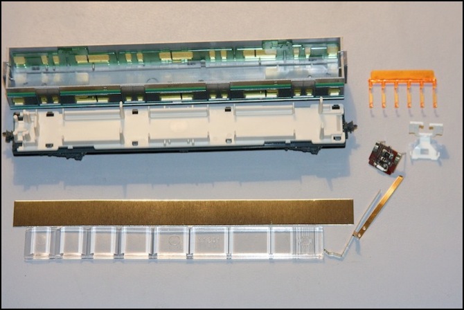
The picture above shows the car, with top removed, the orange plastic used to color the LEDs if you want “incandescent” lighting rather than “fluorescent” (not used on an E231, where bright white light is prototypical). Just below the orange plastic are the lighting control board, and the white plastic holder it snaps into. Below that are the two contact strips to be added, the long silver reflective tape, and the clear plastic diffuser.
In the left picture above, the two brass contact strips have been inserted into the car (one is sticking halfway out to show how it goes), and the lighting control board has been inserted into the plastic holder. In the right picture, a 6mm strip has been cut off the reflective tape, and applied to the lighting board to hold it in the plastic holder (being careful not to touch the exposed metal tabs that will touch the brass contact strips.

In the left picture above, the reflective tape has been applied to the roof of the car, and the plastic diffuser snapped in. The car bottom has the contact strips installed, but not the lighting board. On the right, the lighting board can been seen slid in against the contact strips on the right end of the car.
Below is a larger view of a cab car with the lighting board and diffuser, which is cut short to leave room at the left for the cab itself (note that the diffuser needs to be shifted far enough to the left that the plastic holder for the lighting board at the far right does not bump into it. If the car body has problems going back on, the diffuser is probably out of position.
When I first put the car on the track, the lighting operated intermittently (and that was after I adjusted the board so it worked at all, it’s easily knocked out of position when re-attaching the body). However, after letting it sit overnight it seemed to settle down, and began working much more reliably.
The whole process was incredibly frustrating at times, but having (nearly) done one set, I think I know where the problems are, and the next one should go much more smoothly. I hope.
I had wanted to add figures while I had the cars apart, but eventually decided to forego that for now (see my Detailing a Kato EMU page for that project). However with car lighting in, the large windows of the E231 make it very obvious that the interior is beige plastic with no riders. I’m definitely going to need to populate these trains, and probably paint the bench sets to look like upholstery.
A Note on Power
With one set done, I put the whole train on the track. The results were surprising. Using my Zephyr (13.8 volts DCC output), the total current draw peaked at 0.07 Amps for a 6-car train with two FL12, one EM13 and six interior light boards (non-DCC version). And typical draw was around 0.05 Amps for a moving train.
That’s far less than the “0.3 Amps per train” most people cite as a planning figure. Motor stall current is around 0.24 Amps (240 mA), but that’s not usually needed. So, 300 mA is probably a worst case representing a stalled or just-starting train, and typical power for a ten-car train is around 100 mA.
Parked, and with only the interior lights on, a ten-car train consumed just 0.03 Amps, and with one car removed it dropped to 0.02 Amps, indicating a power requirement of about 3 mA per car for lights. That’s a tenth of what a LED normally draws, so Kato has clearly built in a substantial safety margin against overpowered tracks.
This also means that power planing for DCC power districts (i.e., the number of boosters and the number and length of tracks served by each) needs to take this into account. A 2 Amp booster could run nearly 20 trains, or around three times that number that were parked in a yard if only one or two would typically move at a time. Of course if you also have older trains with less efficient motors and bulb lighting, you’ll need to allow for their higher power demands.
Note: Kato’s new lightboard draws more power, but a ten-car train still peaks at just 200 - 220 mA with running up a 2% slope.
Links of Interest
General References
JNS Forum DCC Page
DCC for Motor Cars from Akihabara Station (decoder selection)
DCC for Cab Cars from Akihabara Station (decoder selection)
Kato EM13 (motor car) decoder installs
E231 install from Yamanote-sen (EM13 install in E231; good explanation)
E231-500 Yamanote Line install from Akihabara Station (EM13 and FL12 install; detail on orientation)
E4 Shinkansen decoder install from Akihabara Station (EM13 and FL12 install)
A very brief example (in Japanese) of an E231 decoder install. (click the left link below the photos to see a couple more)
Wired decoder installs
EF66 install from Yamanote-sen (DN163K0a not quite “drop-in” install in an EF66; how to use aluminum foil)
787 Relay Tsubame (that’s a train) decoder install from Quinntopia
Other
See my Kato DCC Decoders page for information about decoders for Kato locomotives.
