


Preventing Flicker
DCC Power Protection Circuits for Car Lighting
Kato makes a lighting kit to add interior lights to some of their N-scale trains. This consists of a small lightboard, some brass strips that connect it to the wheel-mounted pickups (which are pre-installed), a strip of reflective tape and a transparent plastic diffuser. This is fairly easy to install, and does a good job of lighting the car interior. However, these appear to have a problem getting continuous power from the wheel pickups, which is brought out by any roughness in the track. This may be due to the cars being light enough to bounce on the springy pickups, or to a problem with the way power is fed up from those to the lightboard. The motor car is less prone to this problem. This causes the lights to blink repeatedly, or flicker, as the train moves along the track, even with new and very clean track.
Note: Larger versions of the images here can be found in the Car Lighting photo album.
The human eye can notice a flicker as short as 16 msec, but this requires high contrast. With more moderate changes, duration needs to be around 50 - 66 msec to be visible. What this suggests is that a varying intensity light is actually going to be less noticeable than a fast on/off change. It also suggests that the flickers I’m seeing could be as short as 16 msec (but nothing says they are, and I may need to deal with outages of 100 msec, that’s a tenth of a second, or longer).
Some of the problems may be poor connectivity between the lightboard and the pickup strips, which can be mitigated by carefully bending the strips, or potentially by making the connection permanent. However, a test case with one car showed that a permanent bond from the lightboard to the adjacent strips didn’t solve the problem. And in any case, that wouldn’t be a complete solution. Ensuring a continuous supply of power needs something more.
There are a variety of power protection circuits available on the Internet (see references section), and the design is rather obvious. I’m not the first person to come up with this general idea, although I’m not aware of anyone else who’s addressed the issue specifically with the Kato lightboard and the space available in the cars using it.
I worked out the “Voltage Regulator” design in my head while standing in an aisle in my local electronics shop looking at parts, and I’m not a serious electrical hobbyist; this is not rocket science. But I did spend quite a bit of time trying to find out if there was a better solution, as well as trying to determine the exact characteristics I’d need for the components. Part of that involved researching what others had done, and looking at how their experience and designs could influence my plans (see the references section at the end of this page). Eventually I settled on the Simple Capacitor design as both simpler and a better fit for my needs.
Basically, there are two ways to cover an interruption in the power supply: batteries and capacitors. Batteries are good if you need power of a sustained intensity for a long time, capacitors are sufficient if you need power protection for a very brief time. I could use batteries, but then I’d need some way to access them to replace them (a battery holder under the car and a very small battery, or removal of the body shell and a larger one) or a more complicated circuit to recharge them. I’d also need a way to switch them off when not in use. All told, that seems like a lot of unnecessary work, and I don’t really need long run-time anyway. So capacitor storage was the answer.
Before looking a the circuit design in more detail, I needed to define my other requirements, which were:
How much available space do I have?
What power requirement (amps, volts) do I have?
For space, I think I can use about 8 mm x 18 mm for the capacitor before it becomes too intrusive on the car interior. This assumes I’m locating it at the far end from the lightboard and the other circuitry, where it will block the windows and one set of doors. I’ll discuss the capacitor and its relation to the available space more below. As it turns out, I don’t need anywhere near that space.
My power requirement is to work at typical DCC voltages (<18 volts), down to about 10 volts on the track, and I should expect my normal track voltage to be in the 10 - 12 volt range. Because I’m designing this specifically for the Kato LED lightboard, which uses very little power, I also need to support a 3 mA power draw (I’ll design to 5 mA to allow for some component variation). Thus my maximum sustained power rating is going to be 54 mW. However, it turns out that I’ll need some components to handle larger peak currents. I’ll get into that a bit more below. While this circuit would also work on DC, the lower voltage of a typical running train (likely around 3-5 volts) would result in a much shorter runtime for the capacitor.
Caveat: before going any further, I should note that my designs are using 25 volt capacitors. There’s a risk here, as while typical N and HO-scale DCC systems use no more than 14 volts, some beginner’s systems are known to use higher voltages (some even exceed the limit of 22 volts in the standard). And capacitors fail badly when their voltage is exceeded, often with destructive results to whatever surrounds them. The usual practice is to select a capacitor rated for 1.5 to 2.0 times the largest expected voltage. To be safe on all DCC systems, a 35 volt or 50 volt capacitor would be needed. But capacitors get much larger (and more expensive) as voltage increases, and I’m optimizing for N-Scale. If you use these designs for other applications, or if you want to be able to run your cars on someone else’s system, keep this caution in mind, and either test the DCC system first with a prototype or check its voltage with an RRampMeter, or use a larger capacitor.
Let’s take a look at the object of this exercise, the Kato LED lightboard itself, and then we can look more deeply into the answers to those “requirements” questions.
Kato LED Lightboard
The Kato LED lightboard for most of their cars is part 11-209 (available in a six-pack as 11-210), the “Interior Lighting Kit w/ LED”. They also have an older bulb-based product: 11-204/11-205, the “Passenger Car Light Kit (Incandescent bulb)”, however that is not mentioned as compatible with many more recent trains and is no longer listed on Kato USA’s website. Since the LEDs will almost certainly have a much greater lifespan, and use less power while producing less heat, I’m using the LED kits exclusively to add car lighting to my unlit Kato trains, so this circuit only needs to work with those, which greatly reduces the power requirements it needs to handle.
Note: Kato has a new design of the lightboard due out soon. It's narrower, intended to fit the new Japanese subway train models they're producing, but it's also described as being brighter (as if that were needed). It's unclear if there have been other changes.
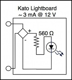
The design of the lightboard is pretty simple: it has three surface-mount components with two pickup tabs that are pressed against the brass strips that supply track power from the wheels. One component, marked “R12”, would appear to be a rectifier, which provides DC power to the LED and its resistor. The resistor is marked “561” which is surface-mount terminology for a 560 Ohm (“56” plus “1” zero) resistor. And my multimeter confirmed that it was indeed a 560 Ohm resistor. That’s a big resistor, but it’s the right size for a ~4 mA current, which is about what I expect is needed for the LED.
The mystery component could be something other than a simple rectifier, such as a current limiter of some kind. Whatever it is, it does rectify the current, as the LED will happily light regardless of polarity.
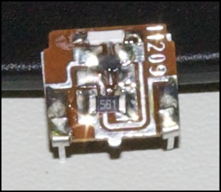
In the photo above, the white block at the top of the board is the LED. The black blob just below it is the supposed rectifier (the “R12” is too faint to see here, but is visible when viewed directly under a magnifying glass), and the “561” block below that is the resistor.
The current draw on these is really low. With ten lit cars parked on the track at 14 volts, my RRampMeter says the current is about 30 mA, and with 9 it’s only 20 mA. Which implies that they’re close to 3 mA each, and probably a hair less.
I initially thought the lighting inside the cars too bright on DCC, so operating these at a lower voltage would be desirable (and it would likely increase their service life). However, after painting the car interiors the light looks much more reasonable
Kato Lightboard 2.0
This all may be unnecessary now. In late 2011, Kato announced a new lightboard for their subway train models in Japan, which is also to some extent compatible with the older models. This is available (in Japan only so far) as “LED interior lighting kit, ver 2.0” in both single-unit (11-211) and six-pack (11-212) sets at about the same cost as the old one (720 yen versus 700 yen for the single unit, about US$9.25 at current conversion rates). This is described as being compatible with existing cars designed for the LED lighting (11-209/11-210) sets, however early reports are that the diffuser that fits into the roof, being narrower, may require additional work to secure in older cars.
While the lighting set is described as being “20% brighter” (as if we needed more light in these), it’s also reported to more evenly light the interior of the car, and to be less prone to flicker than the older design. I don’t have one to try for myself yet. But if so, this may reduce the need for extra circuitry to combat flicker in Kato cars.
DCC Voltage Requirements and Implications for Capacitors
I need this to work on DCC, but for the most part that doesn’t change the voltage requirement significantly. DCC systems can be as high as 22 volts (and some are reputed to be higher), but a typical worst-case is probably around 18 volts, and most DCC systems are in the 14 - 16 volt range. DC power packs can also output more than 20 volts, but again 18 is probably a typical maximum. To be safe, I really should assume voltages in the 20s, which would make my capacitor minimum around 35 volts (the next normal step above 25), but since I’m planning to use these in a DCC world, with 12 or 14-volt DCC systems, I’m going to be relatively safe using a 25 volt capacitor.
If I wasn’t trying to optimize for space, I’d use a 35 volt model; you always want a large safety margin on capacitor voltage, as they tend to fail catastrophically when the rated voltage is exceeded, leaking, bursting, or catching fire; all bad things to occur inside an expensive model. As it stands, I’ll just have to be careful what layouts I run my lighted cars on.
And there’s nothing about the circuit that would prevent it from working on a DC layout, should I run the trains there. At worst, it would provide much less run-time due to the lower typical voltages used.
Space Requirements
I need to fit the circuity inside the car, which imposes some space requirements. More critically, I also need to either fit the capacitor below the light-pipe (which means an effective height limit of around 8 mm) or place it at the far end of the car and run wires the entire distance. If I was willing to do that, 10mm was my limit. In either case, some modification of the interior would needed, and my length limit was probably around 18 mm before I blocked a significant portion of the interior. However, putting the capacitor at the far end from the lightboard, and putting the other components near the lightboard, would leave the middle of the car unblocked (except for some wires, which could be painted).
So, assuming a cylindrical capacitor (the typical shape) I could fit one about 8 mm x 18 mm. That was my most significant constraint.
After the initial testing, I switched to using a surface mount capacitor. I may still mount this at the far end to keep it out of the way, but that’s less necessary given its small size.
Capacitors
One big question that arises is: how much time do I need to keep the lights on, and can I get a capacitor with enough storage in the space I have? Ordinary capacitors are typically rated in microfarads (written μF or MFD; don’t confuse the latter for the typical metric “milli”, it really does mean micro, or one one-millionth of a Farad).
Note: I’ve updated the numbers here, based on some better information on LED run times. Particularly useful was this calculator.
Capacitors have very limited storage, typically not more than hundreds of microfarads if a compact size is needed (a Farad is one Amp-Second, which is large compared to a LED’s demand, but not that large). Models that will fit inside an N-scale train are limited to at most several thousand microfarads, and in practical terms much less. Looked at simplistically, a 1000 μF capacitor will light a typical 20 mA LED for about 200 milliseconds, which isn’t very long. But with a 3 mA LED like the Kato board uses the operational time is likely around a second. Longer, actually, due to the exponential decay of the output being limited at first by the LED’s maximum allowed current.
The largest 10 x 18 mm capacitor I could find (actually 10 x 16mm) rated for 25 volts was 560 μF, and the largest 8mm x15mm was 390 μF. At my planning current of 5 mA, I estimated that the larger one was going to provide perhaps 500 msec of power (or longer). That’s a pretty long time, actually. In practice, runtime turned out to be close to half a second (500 msec) at an acceptable intensity but it remained lit for seconds.
There could be power outages that lasted that long, but that’s not likely with the train moving at a reasonable speed on clean track. In addition, the varying intensity as the capacitor drains and recharges may help make the flicker less obvious even when it’s too long for the capacitor to cover. Side by side comparisons of an unprotected car and the eventual 100 μF circuit showed a very large apparent difference, even when the protected circuit was fluctuating in intensity. The sharp cut-out of the unprotected circuit is just much more obvious.
And I did settle on 100 μF for size reasons, once I determined that it provided an adequate run-time.
The run-time of a capacitor discharging through a resistor is controlled by the “time constant”, which is a function of the start voltage, capacitance and resistance. For a Kato lightboard with R=560 Ohms, and a 100 μF capacitor, the time constant is 56 milliseconds. This means the capacitor will fully drain in 168 msec (3x the time constant), but current will fall below the minimum for the LED after about 80 msec. But the LED limits the current to about 3-5 mA from the beginning, which is much less than the capacitor can initially provide. This means the capacitor drains much more slowly, and lasts longer. I don’t know the math for that, but it’s the reason the small capacitor works so well.
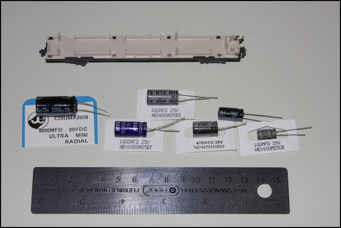
The above photo shows a variety of capacitors alongside an E231 commuter car for size, the second from the right, without the cardboard tag, is the 390 μF one I ended up using in the first on-car prototype. I also tried some of the larger ones in a test circuit on a solderless breadboard.
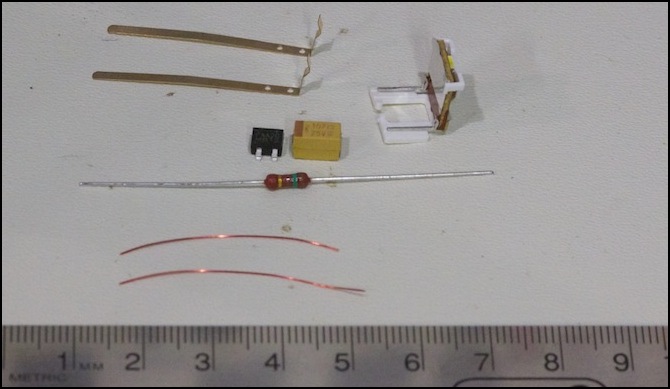
And above is the set of components I finally used, including the 100 μF tantalum capacitor (yellow box). As you can see it’s about half the size of the 100 μF electrolytic capacitor above.
If you’ve made it all this way, now you can skip ahead to either the Light Board page to see the finished circuit, or the Simple Capacitor design page to see the actual circuit design, and the details on why the specific components were chosen. Or you can read on to see what I did to test that circuit, and continue to the next page to see the prototypes.
References
Similar Circuits
Google is very useful for finding other designs for similar problems. I did a number of searches, and came up with several similar plans.
There’s a commercial product which is quite similar to the basic rectifier/capacitor circuit, the ACCW from TrainAidsA (scroll down on this page). From the specs it appears to use a 25V capacitor, which is a lower voltage than I’d feel safe with for a general-purpose solution, given that capacitors exposed to over-voltage tend to fail explosively, or at a minimum leak in a way that could damage the car. That said, the result is a very compact design, and the voltage should work fine for N-Scale applications unless you have a beginner’s system that is seriously overvoltaged. The lower voltage allows a larger (in a capacity sense) capacitor in the same space, which is preferable to a physically larger capacitor, although it still ought to have a resistor to lower the inrush current if you’re going to have a number of them on the track at the same time.
And here’s a design for a Lighting Circuit that does exactly what I was originally planning to do, using a 1000 μF input capacitor and omitting the output capacitor (not a good idea with a 78xx or 78Lxx, as the spiky output will shorten the LED’s lifespan). The rectifier used in this circuit is rather oversized, about 20mm across and rated for 70 volts). This one also lacks any inrush current protection.
Here’s a Constant Lighting circuit using a National Semiconductor LM317T (PDF) adjustable voltage regulator, similar to the LM78LXX used in my Voltage Regulator circuit, except in a larger form factor; this circuit uses a 100 μF or 220 μF power reserve capacitor, but lacks inrush current limiting. I actually found this page after my initial design was done, but it’s similar enough that it’s worth mentioning, and has the advantage that it uses parts available from Radio Shack (although the LM317T isn’t going to fit in an N-Scale passenger car; there are surface-mount versions that would, see the data sheet linked above, but you won’t find those at Radio Shack).
Here’s a page with several Lighting Circuits, some of which use supercapacitors with the LM317, a variant of the LM337. Unfortunately the supercapacitors (storage of one Farad or more, sold as memory backup capacitors) are an inch or more in diameter, making them unsuitable for N-scale use.
Here’s a DC Continuous Brightness Lighting circuit (meaning “lights at low voltage” not “keeps light lit at zero voltage”) using the National Semiconductor LM334Z (PDF), a “constant current” control circuit. This is an interesting circuit that replaces the resistor typically used with an LED with the LM334Z, allowing the LED to light at lower voltages. However, I suspect that this circuit has some issues with heat generation at typical LED currents, and may be unsuitable for very small spaces.
Technical References
Analogic AAT4610A data sheet. This is a current-limiting MOSFET circuit designed to control inrush current to a supercapacitor used in memory-card applications. I looked at using this in my Current Limiter circuit (on the Voltage Regulator page), but ultimately decided that it didn’t fit my needs.
Heat Sink Requirements website.
Article on Limiting Inrush Current.
National Semiconductor LM78LXX Series data sheet (PDF). This is a simple integrated-circuit voltage regulator, which I used for the Voltage Regulator circuit.
