


Buttons and Switches for Arduino Controls
Buttons and switches are a basic control. These can be thrown by a human, or they can be “microswitches” used to detect the presence of something. Their function is to let current pass or block it, a simple “on” or “off” state. On the Arduino they can be read using the digital pins, which also work with “on” and “off” states.
But switches and buttons aren’t quite that simple, in operation, circuitry and software there is just a little bit more to them than “off” and “on”.
Note: code samples on this page are released to the public domain (the other contents and the page itself is covered by the creative commons license at the bottom of the page).
Types of Switches
Whether a switch is called a button or a switch is a matter of the physical design, but both are switches in the sense that they “switch” a circuit between two states. The word “switch” is normally used when referring to a lever, which can be thrown to an “on” or “off” position and remain there. But it can be a button where one press puts it “on” and another puts it “off”. A button in turn can be made to act like a switch as just described, or such that it is “on” (or “off”) only while being held down, and returns to its normal state when released. Finally, either can be “momentary”: when pushed or thrown it turns “on” (or “off”, although that’s less common) briefly then returns to its usual state even if the button or lever remains held.
Of all of these, the “momentary” form is least suited to being used by an Arduino, because if the Arduino is busy during the brief time the switch is in its new state and doesn’t read it until later, the fact that it was pressed at all may be lost. I’d suggest not using momentary switches (often described as “(on)” with the word in parentheses) with an Arduino.
A switch can also be a multiple-throw type, where two (or more) electrical switches are thrown together by one mechanism. For Arduino use, a single-throw (or “ST”) switch is most useful. Finally, a switch can be “multiple-pole”, where one of several different switches is thrown depending on the setting (such as in a control panel selecting from one of several power packs). While a multiple pole switch may have uses, and could be treated as a collection of single throw (or “ST”) switches, it would probably be simpler to treat one as an analog control to be read several states with one analog pin, so they won’t be covered here.
Thus the rest of this page will focus on how to work with Single-Pole, Single-Throw (SPST) non-momentary switches. Some examples that will be used are:
1) Radio Shack 275-0634 “SPST Lever Toggle”, which when thrown remains either on or off.
2) Radio Shack 275-0011 “SPST Push On/Off”, which works the same as #1, except the when pushed and released it changes to on, and when pushed and released again, it changes to off. This one seems to have disappeared from their catalog, but the 275-0617 is similar.
3) Radio Shack 275-0646 “SPST Pushbutton”, which is off except while the button is held down.
Arduino Switch-Reading Circuit
To read a switch, you might think that you just wire it from a voltage source to the digital pin. But it’s not quite that simple. Without additional circuitry when the switch is off, the digital pin has nothing to make it “high” or “low” and will tend to “float”, which may provide improper readings. There are several ways to do this, but they all involve a resistor because you are connecting +5 volts to ground through a switch, and if you don’t have a resistor you have a short circuit the moment the switch is closed.
Standard Button Circuit
The standard circuit described on the Arduino Button page looks like this, where “Dn” is any of the digital pins (or an analog pin being used as a digital one), and “Arduino Ground” is any of the Arduino pins labelled “Gnd”:
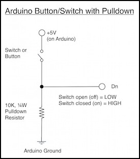
The behavior is very intuitive, which is probably why they chose it for the example.
When the switch is closed, +5 goes in the digital pin (“Dn”), which has internal resistance preventing a short. Some also goes down through the pulldown resistor. The net effect is that there is a +5V difference between where Dn is connected (above the resistor) and ground, which the Arduino’s internal circuitry can measure. On a 5V Arduino’s digital pin, voltages below some threshold are reported as LOW, voltages above a different threshold are reported as HIGH (and in between could be reported either way). So, with the switch closed, the pin “sees” +5V and reports HIGH, with it open it reports LOW.
This is nicely intuitive, and the program to read its present value is:
pinMode(buttonPin, INPUT); // do once in setup
integer buttonState = digitalRead(buttonPin); // do in loop as needed
Note: you can add a safety resistor on the digital pin of a few hundred ohms, but it isn’t really needed as the default state of the pin will be INPUT and you can only have a problem if you somehow set it to be an OUTPUT pin and then somehow bypass the pulldown resistor to short the pin to ground. In INPUT state, the pin has an internal resistance of 20 K ohms that protects it.
The pulldown resistor can likely be any value from 1 K Ohm to 10 K Ohms, or perhaps even more widely. A value of 10K Ohms is perhaps best, but I’ve used 2 K Ohms successfully. Since very little current actually flows through it, all you need is a 1/4 Watt resistor.
Pullup Button Circuit
There is a second way to do this, connecting the pin below the resistor:
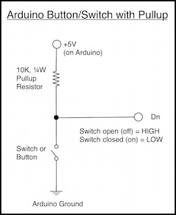
This is a bit non-intuitive, since a closed switch now causes the program to return LOW rather than HIGH because you’re measuring ground if the switch is closed, and +5 if the switch is open. It’s read the same way, and for a simple switch doesn’t provide any benefit. So why do it this way? Because if you are using an active external circuit rather than a simple switch, it turns out to often be easier to generate a really low voltage than a high one.
For a switch, there’s no benefit to this approach, so it’s usually ignored. But...
Internal Pullup Button Circuit
The Arduino’s pins come with an internal pull-up resistor you can enable. It’s a pull-up because that makes it more useful for things other than simple switches. To use it, you simply wire the switch between the digital pin and one of the Arduino’s ground pins, and turn on the feature. If you forget to turn the pull-up resistor on you won’t blow anything, but you will be measuring a floating pin so the results won’t be correct.
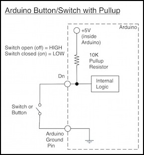
The software now becomes:
pinMode(buttonPin, INPUT_PULLUP); // do once in setup
integer buttonState = digitalRead(buttonPin); // do in loop as needed
You may also see examples that use pinMode to set INPUT and then use digitalWrite to set HIGH, which looks a bit odd but does the same thing as INPUT_PULLUP.
Aside from the fact that this is reading the switch “backwards” from what you might expect (an “on” switch reports LOW) it’s a lot simpler to wire, and so it’s really the preferable way to do things. And, you can always set an internal variable based on the switch to a more intuitive value, such as:
boolean buttonIsOn = (digitalRead(buttonPin) == LOW); // true when switch closed
Now your variable will be true if the switch is closed (on).
Switches and “Bouncing”
But just reading the “current state” of a switch isn’t sufficient. You need to do a bit more, in software, to get it right. This doesn’t change the circuit (and it is needed regardless of which kind of switch-reading circuit you use). But if you don’t do it, sometimes you’ll read LOW when it should have read HIGH, or vice versa. Welcome to the wonderful world of switch de-bouncing.
A switch has internal electrical contacts that are made from metal, often brass. These are flexible, to allow the switch to make a firm connection by pressing them together without permanently bending or breaking them. But “flexible” means that they can act like springs, and it is not uncommon for the contacts to bounce apart and then back together, possibly even several times, when a switch is closed, before settling into the final state. Apparently this can happen on an opening switch too.
Additionally, because there’s a middle-ground between LOW and HIGH where the switch can be reported either way, even a clean switch that doesn’t change instantaneously can report “bouncing” states because of the way digital logic works (see this site for a very detailed discussion). And this can happen on opening switches as well as closing ones.
Finally, electromagnetic interference (noise) can cause a spurious signal on a wire by inducing a voltage. As long as this is not continuous, it likely results in sporadic misreadings that can easily be ignored by code designed to cope with other sources of misreadings. Extensive noise would call for physical corrections, such as rerouting wires to avoid placing noise sources near switch wires, or shielding wires.
If the Arduino doesn’t attempt to read the switch exactly at the right (or wrong) time, it will never know it bounced. It will, for example, look LOW on one read and then some time after the switch closed it will be HIGH, and everything will appear to have worked perfectly. This time. So a switch that usually works may (one time in a hundred, or one time in three) fail to work properly, for no obvious reason. Testing some common switches I found bounces fairly easy to observe, which means de-bouncing switches is a fairly important thing to do if you care about reliably detecting changes, and only changes.
For some things this doesn’t matter. If you’re turning a light on, the fact that it went on, then off, then back on (perhaps repeatedly) in the space of a few milliseconds won’t affect the light or be visible at all. As long as you eventually read it and realize that it is now on, that’s all that matters.
On the other hand, a push button being used to count things should record exactly the number of times it was pressed, not the number of times it bounced.
If you can ignore spurious misreadings due to bounces, then simply read the pin and react to whatever state it is in immediately. But if you need to be precise, then you need some additional software to “de-bounce” the switch.
Ironically, when looking at the behavior of the switches with my oscilloscope, the one I got the best-looking bounce from was the one the software never reported a bounce for when I was doing my initial testing, the lever toggle switch #1. Over the first 100 microseconds (about 6 - 25 digitalRead cycles if the Arduino is doing nothing else) it was high, except for one downward spike), then it went back low for another 100 microseconds, before finally stablizing at high. By the time I caught this, I was already deboucing the software, so it never saw it. But had I not been, this would have counted an extra low-high transition easily. Since it stabilized after just 200 microseconds, the delay I’d need to use to debounce this switch would be quite short. Maybe.
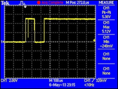
This is what a bouncing switch looks like (switch #1)
But bounces don’t just happen on that timescale. Here’s my more troublesome switch #2. This one has a bit of a hiccup about 180 milliseconds (not micro, milli) after it was thrown. This matches some of the odd behavior I’ve seen with this switch. It’s possible this isn’t the switch at all. It could be the wires on the breadboard moving and making an intermittent contact. I don’t think it is, as I haven’t seen this kind of spike on all of the switches, just a couple.
I should mention that the decaying curve here is because I’m measuring voltage at the Arduino pin relative to ground, meaning across the 2 K Ohm resistor, and apparently that’s evening out over time (I’m not too clear on just what’s going on there, but I think it’s an artifact of my scope and not real behavior in the circuit; pay no attention to the man behind the curtain...).
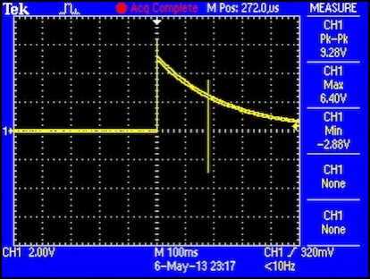
And here’s a bounce with a long delay (switch #2)
I wrote some software to detect bounces and report them, and on a few of my switches saw them up to 50 milliseconds after throwing the switch. I never caught one any later, but I didn’t look too hard for those (and there’s a lot of time, and bounces are short, so statistically it gets harder to find them by simple chance the latter they occur).
Cheap Switches
Some really cheap switches simply use two long strips of brass held at one end, and push them together (I’m looking at you, Kato turnout control). Those things are reported to bounce like a trampoline, because they’re essentially springs. I haven’t put one on my scope yet, but I plan to. Avoid using really cheaply-constructed switches with digital circuitry. Go buy something from Radio Shack for $3, it’s worth it in avoided headaches.
Reading a Switch
As mentioned above, the basic instruction to read a switch is simply the digitalRead function:
const int buttonPin = 2; // assume we’re using digital pin 2
pinMode(buttonPin, INPUT);
int val = digitalRead(buttonPin);
It’s not exactly complicated. The digitalRead command will take somewhere between 4 and 16 microseconds (not milli, but micro) to read the pin. I’m not sure why it varies, looking at the code that defines digitalRead, it shouldn’t be taking more or less time. Actually, since 4 microseconds is about the smallest increment of time an Arduino can measure, the command could be taking less. In any case, it will return either 0 (LOW) or 1 (HIGH) in an integer.
I find it easier to work with buttons as true/false booleans (and they take less space, one byte compared to two for an integer), so I don’t want to be using HIGH and LOW anywhere other than where I’m doing the first check on the read value. So my first order of business is to convert the reading to a boolean.
You can do this quite simply with a type cast, because both are really just using 0 and 1 (look at the source code for digitalRead and you’ll see):
boolean isOn = (boolean)digitalRead(buttonPin);
Note: this works, and since the Arduino uses C++ and in C++ “true” always equals “1” its even guaranteed to work as digitalRead always returns either 0 or 1 and nothing else. Unless someone decides to change the implementation of digitalRead to return something other than an integer containing 0 or 1 it’s always going to work. That’s highly unlikely. But if you want to be a purist, a completely clean implementation would be:
boolean isOn = (digitalRead(buttonPin) == HIGH);
All of these take the same amount of time (to within the measurement accuracy of the Arduino timer) so you might as well use the clean one. Additionally, all of the above has been for a pulldown resistor circuit. As noted earlier, a pull-up circuit has HIGH and LOW reversed relative to the state of the switch, and this last method provides for a clean way to compensate for that:
boolean isOn = (digitalRead(buttonPin) == LOW);
I’ll use this in subsequent examples, as I plan to use the internal pull-up resistors in my program.
Detecting a State Change
The simplest way to know that a switch has changed state is simply to keep its last known state in a variable, and check against that:
boolean switchOn = false;
void loop() {
boolean nowOn = (digitalRead(buttonPin) == LOW);
if (nowOn != switchOn) {
// it changed, do something
switchOn = nowOn;
}
}
But this ignores the fact that you don’t know why the state changed. Did a human throw the switch? Was it still bouncing from being thrown earlier? Was there a random bit of electrical noise on the wire misinterpreted as a change? This code alone will return erratic results. And in electrically noisy environments like a model railroad, it can return very erratic ones.
Ignoring Spurious State Changes in Software
If the switch bounces, you may miss it anyway, since the read only occurs once each time around the loop, and a normal loop could actually take a fairly long time (in microseconds). Even doing nothing else, my reads didn’t always catch a bounce on a switch I knew was bouncing, and they never caught more than one. So you might think that your switch doesn’t have a problem. But it probably does, and you’re just getting lucky. As I mentioned above, the switch I saw bounce the most (#1) on my scope, never got caught bouncing by my software, because I just didn’t happen to read it at the right time.
To eliminate false state changes due to bounces, you mainly just need to ignore changes until they’ve persisted long enough that you can be sure that they are no longer transient. There are several common approaches to this. These generally divide into two types: taking repeated samples until all recent samples agree, or waiting some amount of time for changes to stabilize. The former usually assumes some kind of regular polling, so in a sense it’s timer-based as well.
But you also need to take humans into account, if what you are doing in response to the switch should be “instantaneous”. Most people will notice a 100 millisecond delay. Few if any will notice a 50 millisecond delay. Much depends on what the specific control is doing. A person isn’t likely to be bothered by even a very-noticeable 250 millisecond delay in a light switch. However, if the switch is the trigger for a weapon in a video game, even 50 milliseconds of lag from pulling the trigger to firing the weapon may be noticeable to a highly focused gamer. That’s something to keep in mind: all switches aren’t equal, and different applications may have substantially different requirements.
Simple Code - Poll Until All Agree
The simplest code is just to read the pin, delay a few milliseconds (perhaps 10), and read it again. If it’s changed to a new state in both reads, then it should be stable otherwise assume it didn’t change this time, and go on with the program until the next time around the loop. One problem with this approach is that while you do the “delay”, the Arduino can’t be working on anything else. Also, you may simply read two bounces (out of dozens). Or you may read two “good” readings, while the switch continues to bounce and later misread one of those. It can cope with simple noise. And you will avoid some problems, but most certainly not all.
int firstRead = digitalRead(buttonPin);
delay(10);
int secondRead = digitalRead(buttonPin);
if (firstRead == secondRead) newState = secondRead;
I’m not sure who originally came up with this. I’ve seen it on a number of websites. I don’t think it’s at all a good solution.
Using a “delay” works for a simple program, but if you have several buttons and other things (like sensors) that need attention, wasting time like that isn’t a good idea.
Additionally, you might hit a late bounce on the second read (but not the first), and then you will reject the change, so you still need some way to check again even later. Simple doesn’t work reliably unless you make it complicated, so you might as well put some effort into getting it right in the first place.
You can elaborate this with multiple reads (usually at regular intervals) over a longer period, keeping a circular buffer of the N most recent reads and waiting until all N agree, which will definitely improve the reliability. Done badly this uses a lot of storage in SRAM, which is wasteful. Solutions using this approach can be quite elegant if done well, and suited to working on multiple switches simultaneously if they appear as bits in a single register. Implicitly this is creating some period over which all samples must be “good”, although the period is not explicitly stated (it’s the number of samples in the buffer times the delay between samples).
And you need not do a time-wasting delay, timer interrupts or other methods to trigger the periodic checks can be used. Still, it’s not the approach I’d choose.
Better Code - Explicit Debounce Interval
Similar to the “poll until all agree” method, is to periodically read the switch, keep track of when you read it and first detected a change, but don’t actually process the change until it has remained in the new state for a suitably long time, clearing the “wait” if it reverts to the old state during that time. This essentially waits until the worst bouncing is over and has been over for a “long” (in switch terms) time, but depending on what you use for that “long” time, you may not avoid detecting a final, late, bounce, so it’s not a perfect solution, just a “good” one. This is similar to an elaborated version of the delay and re-check approach, but the time to wait until the signal has stopped bouncing is explicitly stated, and the times between samples are not necessarily equivalent (although more are definitely better than fewer, as they provide more opportunity to notice ongoing bounces).
While this code has some similarities to others (all debounce code is fundamentally just a matter of waiting until the bounces stop), I developed it on my own. It was probably influenced by the example routine in the Arduino IDE (available online as well), originally by David A. Mellis and modified by Limor Fried. However that code is simply waiting N milliseconds after the first hit, to see if it reads the same value again. It doesn’t reset its timer if a bounce is observed while it is waiting. There are a lot of variations on the Arduino code floating around, most without crediting the original. While I don’t recall reading it before I wrote mine, it’s quite likely that I had and that it influenced my thinking, so I think some credit is due the original.
The code to do this is:
const int buttonPin = 2; // whatever pin you use
const unsigned long bounceTime = 20000;
unsigned long waitStart = 0;
boolean switchOn = false;
boolean waiting = false;
void loop() {
boolean nowOn = digitalRead(buttonPin) == LOW);
unsigned long readTime = micros();
if (waiting && (nowOn == switchOn)) waiting = false;
if (((nowOn != switchOn) && !waiting) {
waiting = true;
waitStart = readTime;
}
if ((nowOn != switchOn) && ( (readTime - waitStart) > bounceTime )) {
// it changed, do something
switchOn = nowOn;
waiting = false;
}
}
You can actually make this even simpler, once you notice that when waiting != true, waitStart is undefined, and when waiting == true, waitStart contains a non-zero value. Simply adjust the code to use the timer as the “am I waiting?” indicator with waitStart set to zero when not waiting. Here’s that version, reduced to a simple function with a constant BT_BOUNCE_TIME you need to set to the number of microseconds to wait for the switch to stabilize:
// call this with switchOn containing the value read by buttonOn the last time it was called
// and note that waitStart must start at 0 and be preserved between calls.
// Both parameters are specific to one pin; if multiple pins are being read, each needs its
// own switchOn and waitStart variables.
void buttonCheck(int buttonPin, boolean& switchOn, unsigned long& waitStart)
{
boolean nowOn = (digitalRead(buttonPin) == LOW);
unsigned long readTime = micros();
if ((waitStart > 0) && (nowOn == switchOn)) waitStart = 0; // clear pending change
if ((nowOn != switchOn) && (waitStart == 0)) { // start pending change
waitStart = readTime;
}
// accept pending change as stable
if ((nowOn != switchOn) && ( (readTime - waitStart) > BT_BOUNCE_TIME )) {
waitStart = 0;
switchOn = nowOn;
}
}
Here are a few other methods I found online:
- a very simple elapsed-time method done as an Arduino library
- a multi-button elapsed-time method, optionally using interrupts
Setting Timers
How long is a bounce? Well, “it depends”. What I observed was that switch #1 wouldn’t bounce at all (or as I found out later, that it bounced so little that I never caught it in my testing). Switch #2 would be caught bouncing once almost every time, and would take about 1,500 microseconds to bounce (rather odd that I always seemed to catch it at the same time). And switch #3 would bounce occasionally when I didn’t press firmly enough, and times would be around 50,000 microseconds. Unless it’s really critical to react quickly to a switch being closed, its probably safest to set the window (bounceTime in the example) to 100000 microseconds (or 100 milliseconds). But if you want to be more responsive, you can always test your own switch and see how quickly it bounces, and a value of 50000 microseconds (or 50 milliseconds) may be sufficient for a switch other than type 3, and below the threshold of human perception (but see below). For most normal switches, 20000 microseconds is probably a good choice, as you’ll have some initial period of bouncing that could last 10 milliseconds or more, and then you’ll wait your 20 milliseconds, for a total of around 30, which is still well below the human perception threshold.
The type 3 switch is a bit more complicated, because it will only remain on while the human is pushing the button. How long is that? Well, holding the switch in one hand and tapping it with the other as quickly as I could, I could get it to go on then back off in under 57 milliseconds. However, that was probably biased by the fact that I was holding it and it tended to move when I pushed it. If it had been mounted unmoving in a control panel, perhaps I could have done better. I think the lesson here is to avoid that kind of switch, or tell the user that they have to “press and hold” for a time for it to work. Because if you set the bounce window to 50 milliseconds, you might miss a legitimate press, and you might catch a bounce; the two are just too close together with that switch. I’d use 100 milliseconds for that type of switch myself (and I plan to use one for the “emergency stop” on my Tram Controller, so this isn’t an academic exercise for me).
But there was one more oddity. After writing the above code, which worked and gave me bounce-free transitions, or so I thought, I added a few println statements to the if blocks to watch just what was going on, along with printing out the times. What I saw was that after a 10 millisecond delay when switch #2 had successfully transitioned to a new state, I’d sometimes see a couple more bounces many tens of milliseconds later trying to go back down to the earlier state. These never persisted, and the switch never changed back, but it appears that this switch continues for bounce in some ways for close to 50 milliseconds after first changing. That lines up with the article I linked earlier by someone who tested a lot of switches: bouncing can persist for a long time.
This reinforces my opinion that I want a fairly long debouncing timer, despite apparently seeing the switch stabilize after a few milliseconds. Another reason to use a longer timer is that the more samples you take in the window, the more likely you are to see a problem.
In an Arduino loop that did nothing but read one pin, you might be able to read that pin more than 2,000 times in 20 milliseconds. In my program, with several analog reads taking place, I’ll be lucky to read it ten times. Extending the window to even 40 milliseconds would double that to twenty samples, which will probably improve the reliability.
Twenty milliseconds is what I’m using now in general, but I may go to 50, or even 100 on individual controls if I think the delay won’t be an issue.
This may not be the best way to debounce the switch either. I think it could be too slow to react to a switch with persistent bouncing, and it could produce false results with “on while held” switches, which can cycle fast and bounce long. I probably need to do more work to handle those reliably. But for simple things like toggle switches, this works very well indeed.
