


DC Power Supplies
Many things on a layout other than trains require electricity. On a simple one you can use the “accessory” output of the DC Power Pack (throttle), but that’s really not the best choice. This page will discuss the different kinds of power supplies available, and related information like capacity and fusing. It’s intended to be the root of a set of pages about power supply issues, although the others have yet to be created.
Power Supply Components
What makes up a DC power supply? There are basically three parts, although you can add other things: the transformer, the rectifier (bridge) and the filter.
The purpose of a power supply is to convert household voltage (120 Volts in the U.S.) to a lower voltage, such as 5 or 12 volts, suitable for powering small equipment. So to start there will be a power cord, and for safety a fuse on one side of that cord. A ground isn’t required, but may be provided. Usually a power switch will also be placed on one lead, although again this isn’t required. In a simple power supply, like the ubiquitous “wall wart” supplies, the fuse will be internal and self-resetting, and there will not be a power switch.
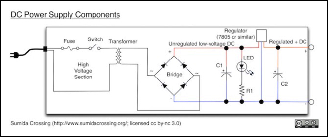
The transformer handles the first stage of this, reducing the higher voltage to the lower. Transformers only work on AC power, so at this point the power is still AC. Transformers can produce more than one output voltage, but usually only one will be provided, and any lower voltage created via a regulator. However, regulators are inefficient, while transformers are very efficient, so sometimes a more expensive transformer with multiple outputs will be used.
The second portion of the supply is the rectifier, which converts AC to DC. This is basically four diodes arranged in a square arrangement, known as a bridge, bridge rectifier or diode bridge. This is so commonplace that often it is supplied as a single semiconductor with four leads. A rectifier converts AC to DC, at the cost of some voltage (so the transformer has to provide a slightly higher voltage than is really needed). However it doesn’t do anything about the fact that the incoming voltage is a series of waves that go to 0 volts 120 times a second. For that we need a filter, or basically just a big capacitor. In the diagram above, C1 is the filter capacitor.
The capacitor connects between the positive and negative outputs of the rectifier, and smooths out the output power. For a typical supply, this is probably a few thousand MFD (micro-Farad). Big, but not outlandishly large. And because it’s working on the DC output, it can be an inexpensive electrolytic (can type) model, although it should be rated for at least twice the output voltage of the supply.
That alone gets you a specific output voltage. However, the voltage is going to go up and down slightly as the wall voltage does, and there’s always a bit of variation in that. For a system that’s intended to be used for microelectronics, having a predictable voltage is important. So most modern power supplies will add a regulator on the output (and usually these require a couple of small, additional capacitors for noise-filtering purposes). Regulators aren’t very efficient, since they simply throw away excess voltage as heat. Depending on the input voltage to the regulator, relative to the intended output voltage, the regulator may or may not require a small heat sink. Regulators can only reduce voltage. And, again, they’re simple semiconductors and need an input slightly higher than the output, so if you’e going to use one, that has to be planned as part of the transformer selection.
In the diagram above, C2 is the output filter capacitor for the regulator (a typical size is 0.33 MFD). A similar capacitor may also be placed on the input side of the regulator, but is sometimes omitted. These are placed very close to the regulator, to reduce the effects of noise on it.
Even regulators aren’t exact, and output voltages may be a few percent off from the rated value.
In more expensive systems, the regulator can be replaced with a DC-DC converter. This is a semiconductor circuit that efficiently produces a set DC output from a higher DC input. Regulators use a fairly standard three-lead design (DC + in, ground, and DC + out) and DC-DC converters (often called “buck converters”) are often designed to have compatible pins so you can simply replace one with the other (the semiconductor models often cost US$15 or more, where regulators only cost a couple of dollars).
And unless you want to spiff the design up by adding a voltmeter (or voltmeters) or an ammeter, there’s really nothing more to a power supply than that.
The first electronic circuit I ever made from scratch was a 5V power supply (for powering other things I built later). I still have it, about 40 years later, and it still works quite well. Power supplies are very sturdy circuits, although the capacitors can prove problematic over time. If you’d like to build your own, Popular Science has a nice article on making a dual-voltage +5V / +12V supply, although it’s lacking a bit of detail. This design is nice because it shows how you make two output voltages from one transformer using regulators.
For a more hands-on explanation, see this instructable on building a similar 12V supply (this one is for 240V power, but it’s otherwise the same for 120V, you just need a different transformer). The PS supply is almost identical to the one I made (in fact, they appear to have used the same Radio Shack kit box and probably built it from the same Radio Shack plans I used), although mine only had one voltage, and used a LED rather than a neon bulb.
These days, if you need a 5V or 12V supply, it’s more practical to simply buy a wall-wart of the appropriate size. But making your own is fun, and a great learning experience. Just be sure to fully insulate the input wires everywhere (at the switch, fuse, and connections to the transformer), as those carry potentially lethal 120V current. And test the resulting circuit with a multimeter, to make sure high voltage isn’t showing up somewhere it shouldn’t.
Accessory Voltage
Most older accessories are designed to operate on the accessory output from a power pack, which was usually somewhere around 18V, and AC (alternating current) rather than DC. This was simply the output of the transformer inside the power pack that was also provided to the throttle system. Often these accessories would say that they were for “16V”, but in order to work they actually had to tolerate power supplies that might put out more than that. Examples include grain-of-wheat lightbulbs and solenoid-driven turnouts. If you’re using any of those, you do want to provide them the power they are expecting.
If you are dealing with modern electronics, LED lights and similar, usually these will expect DC power, and it will be more efficient to provide a lower voltage, often 5V, 9V or 12V DC. That isn’t always true, as some may be engineered to expect 18V AC. As with anything, check the written specifications from the manufacturer.
You may end up with several different kinds of systems with different expectations of voltage. That’s not a bad thing, as it’s almost always a good idea to use separate power supplies for capacity or noise-isolation reasons, as we’ll get to in a bit.
Capacity and Amperage
While voltage describes how “intense” the electricity is, current describes how much of it there is. Current is given in Amperes (or Amps). Actual “power” is the product of voltage times current, and is given in Watts.
Usually when we deal with model railroad electronics, we need to deal with fractions of an Amp, so we use milliAmps (mA). One milliAmp is 1/1000th of an Amp. Power supplies will have a rating in either Amps or milliAmps, but what matters is the total.
A power supply can’t provide more amps that it is designed to provide. If you hook up more loads to it than the rating allows, one of two things will happen: it may adjust to the added load by reducing its voltage, or it may simply attempt to provide the extra current and damage itself (likely by overheating) in the process, and fail. Neither of these is good, so it’s important to consider the capacity of a supply (in Amps or mA) when hooking things up to it, and to understand how much load (in mA) each provides.
Complicating this is that not everyone will tell you what load their accessory or device provides (i.e., how much current it needs). If you have a Watt rating, then divide that by the voltage to get Amps. Similarly a milliWatt (mW) divided by voltage will give you milliAmps (mA) of load.
Here are some typical loads (these are mostly worst-case, meaning highest, numbers):
- small incandescent bulb: 60 mA
- colored LED: 30 mA
- white LED: 50 - 60 mA (or more)
Note: LEDs come in a broad range, from those using 5 mA to ones using hundreds, the above numbers are typical “worst case” numbers, and real use is often lower, but could be higher.
- tortoise switch motor: 16 mA (stalled) @ 12V
- solenoid switch control: 1.5 A
Note: solenoids are often arranged so that one control throws multiple turnouts, so multiply the current needs. These can often be very many amps, so Capacitive Discharge Units (CDUs) are used to throw the turnout, and have a recharge period where they draw current to refill their capacitors are a lower rate (but still probably more than 1 Amp).
- small motors: tens to hundreds of mA
Many modern devices use power supplies where the transformer (or equivalent) is in a block that plugs into a wall outlet, providing low voltage AC or DC via its power cord. These often have capacities of hundreds of mA up to a couple of Amps. Costs run from around US$5 to US$50, depending on capacity, whether or not they are “regulated” (closely maintain the specified voltage) or are a commonly used size. Many supplies of this sort using a larger “brick” with a power cord to the wall also exist, and are basically the same. These are often made for computers but last much longer than those do, so finding used ones at a reasonable price may be possible.
If you want power supplies rated for more than a couple of Amps, self-contained power supplies, usually made of metal with an open cage-like structure for cooling, are available. These can get quite expensive. However, it’s also possible to recycle power supplies made for desktop computers, with some care.
More current means more damage in a short circuit (and a more expensive power supply you might destroy that way). I tend to prefer smaller supplies for exactly that reason. However, with output fusing (something I also recommend, more below) that’s a manageable problem.
Variability and Noise
When we use the word “noise” about an electrical circuit, what’s meant is that instead of the DC being constant or the AC being a smooth sine wave, there are rapid changes in the voltage. These can be “sags” caused by applying a heavy load (e.g. starting a motor) or quick, “spiky”, changes than come from digital circuitry. Often DC is “filtered” by adding capacitors, to smooth out this noise, but those have to be sized to the particular kind (frequency). A large capacitor is needed to cover even short-lived sags, but won’t work as well at removing spiky digital noise. For this reason you’ll often see different sizes of capacitor used in circuits.
Another way to deal with noise is to not have it. If you have something that produces a lot of noise, like a tortoise switch motor, you should probably use a separate power supply for it than for things that care more about constant voltage (like microelectronics).
For this reason, although a single big power supply may seem more efficient (and may cost significantly less), it’s often a good idea to use multiple smaller power supplies for specific purposes.
Grounding
There are two reasons electrical systems use ground lines: safety and electrical reasons of “reference voltage” or “return current” between two power supplies.
At the low voltages we work with in a layout, safety is not an issue. Most power supplies (modern ones) don’t even include a ground prong on their plugs.
The kind of ground that matters to us, where it matters at all, is a “reference” or “return” ground.
If you’re familiar with wiring DCC, you’ll know that when using separate boosters, they need to share a common ground wire to allow for voltages that leak over (through trains) from an electrical block on one booster to an electrical block on the other to be balanced out. This also provides a “ground reference”, which is important when two systems on different supplies need to agree on what “positive” means.
However, that doesn’t mean that everything needs to connect to the same ground. In fact, it’s a very good idea to keep the ground wire of multiple accessory supplies separate from the ground wire of a DCC system, to isolate noise on one from the other. And neither of these needs to connect to a “real” (earth) ground.
But if you wire up two devices that need to communicate with each other through wires, unless there’s some very sophisticated circuity involved, those two systems need to share a common ground. Note that this assumes both use a DC supply.
What that means is that the two systems should each have their negative outputs connected to each other. You only want that to happen once, otherwise you can create “ground loops”, which can actually damage electrical circuits. But they do need to connect once.
A common method is called a “star ground”, and each supply will have a line from its negative side run to a common point, where both (all) negatives connect together. That’s not the only approach, and they could all connect to a long wire (a “bus” ground), which can be more efficient if they are far apart.
It’s a good idea to make the common ground wire large enough for the largest current of any of the supplies, but mostly this is simply a shared reference for what “zero” means, and carries very little current normally.
Fuses and Protection
A fuse is a one-time current limiter. When current exceeds the allowed amount, the fuse has a tiny bit of metal in it that melts, breaking the circuit. This keeps the wires from melting (or starting a fire). Fuses are very important in any electrical system.
Note that fuses only care about current. The voltage doesn’t matter. So a 1 Amp fuse will blow at about 1 Amp, regardless if the voltage is 9V, 12V or 15V. That’s probably not exactly true, but it’s close enough for real world use to treat them as identical.
You might think that because your wall outlet has a fuse (or a circuit breaker) you don’t need one elsewhere, but that’s not true. Currents that would cause problems depend on the size of the wire, and the wall-outlet fuse is sized for very large house-current wires. Currents that could start a fire on a layout won’t even make the wall fuse warm up.
To work properly, a fuse must be smaller than the maximum size of the power supply. How much smaller is open to debate, but sizing fuses at 80% of the supply rating is a common and reasonable approach. This means that if you have a power supply rated for 1 Amp (1,000 mA), you should use an 800 mA fuse. You might not be able to find one that size, so a 3/4 Amp fuse (750 mA) may be the next best thing.
Fuses aren’t exact though, which is one reason to pick a rating below the supply size. And over time, they can degrade. A common rule of thumb is that loads shouldn’t exceed 80% of the fuse rating. So our 1,000 mA supply protected by a 750 mA fuse shouldn’t have its load exceed 600 mA.
Now again, that’s not exact. And exceeding this 80% number will only cause an under-spec fuse to blow. If you don’t mind the small chance of replacing fuses more often, you can hook up larger loads. I’d still stay below the fuse rating (750 mA), just to be safe.
Other than fuses you can get other kinds of protection: circuit breakers and thermal current limiters. Circuit breakers usually have a small pin that pops out, and needs to be manually pushed back in. This is useful as a visual indicator that there was a short circuit, and as a way to force you to think about the fact that you have a wiring problem. Circuit breakers like this are generally only available for currents of several amps though, so they aren’t useful with smaller power supplies. They also cost more than disposable fuses.
A self-resetting current limiter works on the same principle as a circuit breaker, but doesn’t have a button. It will just reset after it has a chance to cool down. This is useful for things like motors, where you might have stalled the motor briefly, or started two at the same time, and exceeded the limit. In the even of a real short, this isn’t as good as a fuse or circuit breaker, as it will keep turning the power back on and doesn’t provide any visual indication that a short has occurred. But in some circuits, this is preferable to a fuse or circuit breaker.
A power supply will nearly always have either a fuse, circuit breaker, or thermal protector on the line (input) side of the system. This protects against a short-circuit or similar failure inside the power supply. This may also protect against a failure on the load (output) side of the power supply. But depending on the design of the power supply, it may not. For this reason I recommend putting a fuse on the wiring side for each output.
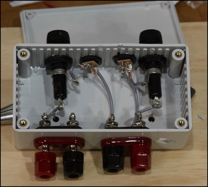
My usual approach to this is to build a “fusebox” This can have one or more circuits going through it. On the input side is a power jack that matches the cord from a typical wall-mounted power supply. On the output side are two screw terminals. The black, or negative, terminal wires direct to the negative side of the power jack. The red, or positive side, ruse through an inline-fuse holder to the positive side of the power jack. If something (like a short) draws too much power, the fuse will fail and break the circuit.
Here’s an example of a simple two-circuit fusebox:
Note: although the wire from the left jack appears to go to the right black output, that’s a trick of perspective, it actually runs below that and over to the left black output.
And here is a large model for eight circuits (with only the first three wired). This one uses posts on both input and output on the first circuit, as it was built for a supply that didn’t use a standard plug.
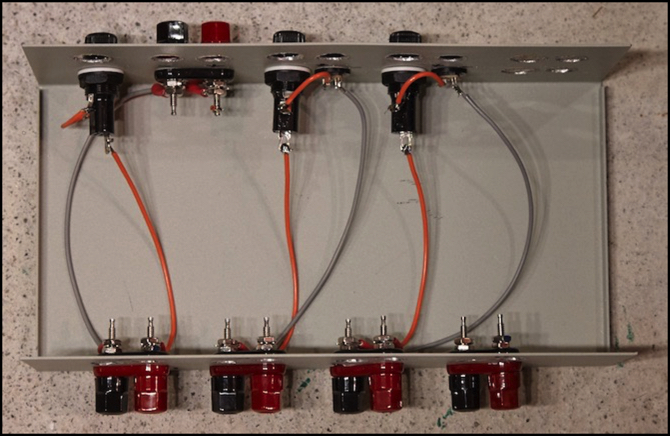
These are easy and cheap to make (the hardest part is drilling holes for the connectors), and well worth the investment of time and money. Mine have served me well for years.
