


WS Lights
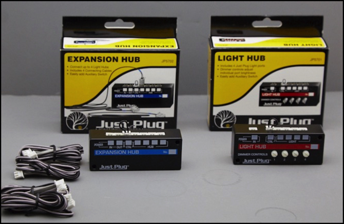
One method of lighting buildings is the plug-and-play system from Woodland Scenics, which uses LEDs on 24” cords that plus into Light Hubs containing all of the circuitry needed to use them, including an intensity-control knob. Curious as I am, I took a set of these apart and ran some tests. This page summarizes those tests and the conclusions I drew from them.
Electrical Testing
My power tests were made using an adjustable benchtop DC power supply and an MRC 220 DC Power pack. As I’ve previously mentioned, DC pack accessory outputs tend to put out fairly high voltage when unloaded, and this was no exception. The 220 put out 18.0 V AC (RMS). For these tests, I confirmed with my multimeter that wall power was normal (121.1 V AC RMS, which is typical for my house).
The wall-wart transformer they sell for use with these is rated as 16 V AC. I didn’t buy one to test, but my power pack test clearly exceeds that.
Reported voltages were measured with my multimeter (a good-quality Fluke) and oscilloscope (a hobbyist-grade Tektronix scope).
Intensity Control
I tried varying the intensity using the adjustment. This has about 3/4 of a circle of turning radius (270 degrees). The lights came on somewhere between 60 and 90 degrees from zero, depending on the power supply (the lower setting worked at higher voltages like 18 volts, at my 12 volt minimum test voltage the control needed to be turned up to about 90 degrees). From there to full (270 degrees) the light increased steadily, and to my eye it appeared to be a smooth change. The knob itself operated smoothly, and could easily be turned with even my oversized fingers. It’s also slotted, so a screwdriver can be used, which would be handy if it’s tucked away in the benchwork somewhere hard to reach.
So the intensity controls work well, and are easy to use.
Light Hub Circuit
Now if you’ve read my site often, you’ll know that curiosity is one of my basic traits, you might even call it a vice. The first thing I think when seeing something like this is “how does it work?”. The second is “how do I take it apart and find out?”. So I did.
It’s pretty easy to disassemble the hubs: two small phillips screws and the back of the case comes off. Inside there’s a circuit board which easily pops out (getting it back in is a bit more work, but not too hard).
The board in the expansion hub is trivial, it just connects the input to the outputs in the way you’d expect from basic electronics (i.e., the Light Hubs are wired in parallel, not serial). There’s a “control” port on it (the one with a plug with a loop of wire stuck in), which just loops out one of the two power inputs and that can be used to connect an external switch. They sell one for US$10, although you could add your own by using half a Connecting Cable wired to a simple SPST On-Off toggle.
You could also run the “control” wire through a relay, and use some external system to activate the lights connected to the hub (or all the lights fed from a string of Expansion Hubs). I can think of some useful applications for that, although they’re outside the “simple” domain.
The board in the “Light Hub” is more interesting. This has the connection for the external power supply and its own control port if you want to switch these four separately, as well as the four sockets for lights and their associated control knobs. I was curious about two things: what kind of voltages was it designed to work with, and how did the intensity controls work?
The circuit board, while not terribly complex, had more on it than I’d expected:
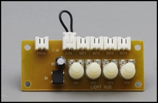
On the left photo, the jack at far left is the power input, and the one with the loop of wire is the control input. You need the wire there because the power passes through that jack. The two objects on the left side of the board are a full-wave rectifier and a capacitor: your basic AC to DC conversion system. The cap is 47 MFD and rated for 35 Volts, a bit small in capacity for this kind of DC supply, but likely enough for lighting purposes. Between the two of them, the output will be fairly smooth DC (and it was, as we’ll see below), so there shouldn’t be any flicker in the lighting that you could notice, even on video. And the 35V rating is more than enough for any model railroad power supply, and a good 2x the size needed for the ones this will mostly be used with; it’s the same rating I’d pick if I were building a supply like this.
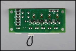
The image on the right shows the back of the board, which is quite busy. There are a total of twelve resistors, in addition to four surface-mount transistors. Tracing the circuit out shows a fairly obvious potentiometer-controlled transistor used for light intensity, and a resistance per light of 685 ohms (built as two parallel 1.37K-Ohm resistors for some reason). I checked with my multimeter, and the resistance was indeed 685 ohms (plus or minus no more than 2 ohms on my sample).
Here’s what I think the circuit looks like:
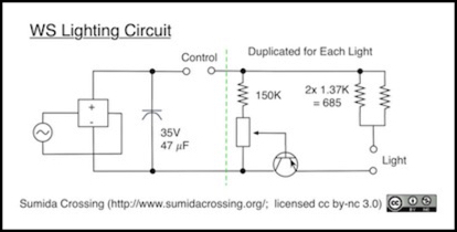
Notice that this means that each Light Hub does its own rectification to DC. This is why a single Light Hub can be used, since it doesn’t depend on any circuitry in the Expansion Hub. Also, this means that the limits of the rectifier do not affect how many Light hubs are in the system.
Calculating the maximum safe voltage off this is difficult, since we don’t have exact specs for the LEDs. I did some back-of-the-envelope math for similar (I thought) components, and came up with 16 Volts as a limit (15.8, actually). But the circuit clearly works on 18 V AC, which has peaks over 21 volts as measured on my scope (below). And while “average” voltage is lower, as I understand it the peak is what matters for a semiconductor junction, not the average.
Power Pack Use
I don’t recommend using the accessory outputs on a DC power pack to drive LEDs. That’s just asking for trouble, for several reasons. That said, the manufacturer clearly states that this system is intended to be used on a DC power pack accessory output. You need to make your own cable for that, by cutting one of the Connecting Cables in half and stripping the ends to attach to the screw terminals, so it’s not quite plug-and-play, but that’s their recommendation, so I thought it best to test against that. There are packs out there that put our more than 18.0 V AC on their accessory outputs, but that is the highest voltage pack I have, and I don’t have a way to produce variable-voltage AC in that range so I couldn’t test at anything else.
I hooked up one LED light (a warm white stick-on version rated at 20 mA), turned the adjustment knob up to full, and connected the Light Hub’s power jack to my pack’s AC outputs, which I confirmed were putting out 18.0 Volts AC RMS. I did this with the light hub’s circuit board removed from the box, so I could get at it and test. I let this run for several minutes. Not a long time, but long enough that the LED would have failed if it were overloaded, and it survived. I then hooked up three more LEDs, all set to full intensity, and did more tests. These also ran for several minutes, with no failures.
That’s not a real stress test, as I’d need to leave it wired up for hours. And even that wouldn’t show if the LED’s lifespan had been significantly reduced due to stress. But at least in basic terms, the system is obviously designed to work on fairly high AC voltage from a power pack accessory output as claimed.
What I saw on my scope in this testing was that the output of the Light Hub’s rectifier was a DC voltage measuring about 21.9 V (“RMS” per the scope) with one light and 20.0 V with four. The difference likely has to do with how the capacitor on the output is storing excess power. It will charge to peak voltage (about 23V) every 8 milliseconds (half a 16.6 ms cycle) and be drawn down by its load. More load, and the voltage will get closer to the average (which should be around 16.2 V DC). Clearly even four of the “20 mA” LEDs weren’t really loading the circuit.
I did see more ripple with more LEDs. And that correlated to the RMS voltage reported by my scope. With one LED, ripple was 2.8 V peak to peak and “RMS” voltage was 21.9V. Assuming 21.9 was actually the median value of the ripple, half of 2.8 V added to that puts peak at about 23.3 V DC. That’s correct for 16.5 V RMS AC, suggesting that about 1.5 V is lost in the rectifier, which is a typical value (rectifiers are semiconductors, and typically lose between 1.1 and 1.6 volts). Increasing to four LEDs of load, ripple increased to 7 Volts peak to peak, with 20.0 volts “RMS” reported, implying about 23.5 V as the peak.
Regulated Supply Testing
I next connected the Light Hub up to my adjustable bench power supply set to 15.0 Volts (and confirmed with my meter that it was producing 15.0 volts). Output of the rectifier was 13.7 Volts, suggesting a 1.3 volt loss in the regulator, which was close to the 1.5 measured in the power pack test, and the difference is likely due to the lower voltage in use.
I then hooked up four of the “20 mA” LEDs, and ran the system at three different DC voltages 12, 15 and 18 volts. The LEDs would not light below 9 volts, and were visibly dimmer at 12 V than at 15 V, so I view 12 Volts as the lowest reasonable DC input power. At 18 volts, total current (per the supply meter) was 40 mA, or just 10 mA per LED, half the rating. At 15 volts this dropped to 20 mA and and at 12 volts to 10 mA, or just 2.5 mA per LED. Now the supply meter isn’t the most accurate tool, but it’s reasonably close. This implies that I’d get the rated current at 21 volts DC (which is about what I had on my 18 V AC power pack test). I didn’t actually test at 21 Volts DC, as I didn’t want to be wrong and blow all four of my test LEDs.
As mentioned, I’d earlier confirmed that the per-LED resistors were effectively 685 Ohms (two parallel 1.37K resistors). At 15 Volts input (13.7 volts rectifier output) and 5 mA per LED, that’s going to be dropping 3.4 volts, meaning that voltage across the LED should be 10.3 Volts less the voltage drop across the transistor (which should be in the ballpark of 1.6 volts, because it, too, is a semiconductor). Meaning I should measure that at 8.7 volts.
With that info in hand, I used my multimeter to measure the voltage drop across one LED (i.e., the two pins on the socket with a LED connected) and found it to be 8.5 volts at full intensity, reducing to around 7.9 V at half-intensity.
This was quite a surprise. I’m used to white LEDs with a forward voltage of 2-3 volts. It turns out that there are a number of high-voltage white LEDs available now, some tolerating voltages in the tens of volts but still operating at relatively low currents. I’m guessing that that’s what they are using here.
Note that this means that you can’t simply plug in your own LEDs then, unless you use the same kind. You’d need to add more resistance to drop the 8.5 volts (or whatever) down to the usual 2-3 volts. Exactly what you’d need depends on what you’d use for a power supply.
Testing Summary
So, my summary is that this system works as advertised. It can operate on regulated DC from about 12 volts to at least 18 volts, and on unregulated AC (such as you’d get from a power-pack) at 18V RMS, which is typical of most HO power packs. And the intensity control provides a wide range of variation, and is easy to use. The system is pretty much foolproof.
Whether its worth the cost is a different question. I cover that a bit in my review of this system, so I won’t discuss it here.
