


Block Wiring Overview
In a DC-powered model railroad, electrical blocks are sections of track that can be fed power independently. This allows trains to run independently in them by connecting separate power-packs to individual blocks via a selector switch. A model railroad using DCC doesn’t need that, as trains can run independently on a single “block”, and the whole railroad could potentially be just one block.
Why, then, would you want to divide a DCC-equipped model railroad into blocks? There are three reasons: the first is electrical power (amperage) requirements. More trains use more power, and more power means thicker wires, and eventually the wiring becomes too heavy to be practical. This has led to limits on the size of DCC power supplies, which limits the number of trains per “power district” (a form of block).
The second is train detection. If you want to create grade crossings that know when a train is coming, or signaling systems that warn an operator of a train ahead, or if you want to automate some part of the train operation, then you need to know where trains are located on the track. I want to do all of those, so I need to plan for occupancy detection.
The third reason is problem isolation. People make mistakes, and some of these affect the power (e.g., running into a switch set against you and shorting the points). Separate electrical blocks with individual circuit breakers will isolate one train from another trains problems. The also make it easier to track down the cause of problems.
All of this does make DCC wiring more complex than the “just two wires” you’ll often hear stated as a benefit of DCC. You can build a model railroad with “just two” bus wires (plus the feeders from them to the track, which can be quite short). But for any complex layout, you’ll benefit from doing more. Even then, there’s less wiring than with a multi-locomotive DC layout. And the wiring is simpler as well, if you plan for it properly.
Power Districts and Boosters
In DCC, power to the track can be supplied by multiple sources. These are called “Power Stations” in the standard, but more commonly are known as “Boosters”. The first booster is typically integrated with the command station, which is the device that merges throttle and other commands and sends the signal to the power station(s) to be added to the track power.
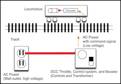
A simple DCC system
Power to run trains is measured in Amps. Power stations are effectively limited to about 10 Amps (which is enough to run 50 - 100 modern N-scale trains without sound). However, ten amps is a lot of power, and a short circuit could cause significant damage. Most boosters intended for smaller scales are limited to 5 Amps, and some of that is headroom to allow the sudden rise in output caused by a short-circuit to be detected. So, if you want to run more than around twenty trains (or run fewer with sound or have others sitting in a yard with lights on) you’re going to need more than one 5A supply, and that means adding a second booster.
Each booster supplies a separate subset of the track, and the two must be electrically isolated from each other. These are called Power Districts. A Power District can be subdivided into electrically isolated subsections using circuit breakers or auto-reversing circuits (a form of circuit breaker used where track loops back on itself). These subsections are often called Power Districts or Sub-districts.
But these are all essentially electrical blocks. And in fact an existing block-based DC layout can be converted to DCC and retain the pre-existing blocks as districts or sub-districts if desired.
Many DC layouts only gapped one rail, a technique called “common rail” wiring. Although DCC supports common rail wiring, it’s strongly NOT recommended. The preferred method is to gap both rails between districts and tie the boosters together with a separate ground wire (which has to be heavy enough to carry the full booster output). This is called “booster common” wiring (Digitrax calls it “home ground” wiring). If you do use common rail wiring, you need to be careful not to have a separate ground between boosters (and/or circuit breakers) as this can create a ground loop, which can damage the equipment.
When converting from DC to DCC, you may also want to add heavier wire from the power supply to the feeders (known as the “track bus” in DCC books). Taking the opportunity to switch from common rail to dual wires when adding the bus is something that will pay you back later in flexibility.
Note: A circuit breaker needs its own power supply to operate. This must be separate from the supply powering the booster(s), as the load on the booster supply during a short will cause a dip in its output voltage, which could impair the operation of the circuit breaker. As a consequence of the above, the circuit breaker’s power supply should probably not be tied to the common ground used by the boosters (except if both are tied to earth ground somewhere as a safety ground). Note, however, that the circuit breaker will have a “ground” terminal which must be tied to the booster ground as described above when “booster common” wiring is used. See the links in the references section at the end of this page for more about such wiring issues.
Block Occupancy Detection
Another reason for electrical blocks with DCC is to use them with detectors that can tell if the block is occupied. These work by detecting current: if something in the block is drawing power, it’s occupied. Thus these won’t detect anything other than locomotives (or motorized cars) unless the car is equipped with lighting, or a resistor between two metal wheels (often added to cabooses on U.S. model railroads so both the front and tail end of a train will be detected).
Occupancy detectors may be used with circuit breakers, or separately. And one power district may be subdivided into multiple occupancy detection blocks.
The primary use for occupancy detectors is signaling systems, although they can also be used for grade crossing activation or in conjunction with computerized train control or simpler automation such as automatic train stop at stations.
Occupancy Detection: A Signal System Example
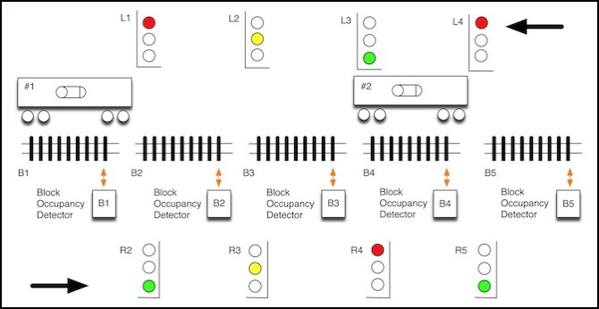
As an example of the relationship of block occupancy detection to track signals, here is a simple three-aspect signal system with one track allowing travel in both directions, based on U.S. practice. The phrase “three aspect” means that signals can have three values, “clear” (green), “approach” (yellow), or “stop” (red). These could be indicated by several kinds of lineside signals, or by “cab signals” (displayed on a computer screen, or on a handheld DCC throttle that supports cab signals, such as the Digitrax DT402). The operator of the train would be expected to stop before entering a block guarded by a “stop” signal, and to reduce speed to a specific intermediate value when entering a block guarded by an “approach” signal. Japanese railroads use similar systems, and for DC layouts, both Kato and Tomix makes signals that work this way.
In this example, there are five blocks (B1 - B5), each with an occupancy detector. Each track segment has a signal at each end controlling access to the block. For instance, track segment B2 has signal L2 at the right end, controlling access by trains moving to the left, and signal R2 at the left end, controlling access by trains moving to the right. Some control system, which could be simple electrical relays or a more complex device such as a computer, lights up the appropriate signal based on information from both that block, and adjacent blocks. So, as shown here, L2 is set to “approach” to warn that B1 is occupied, even though B2 is unoccupied. But R2 remains “clear” because both B2 and B3 are unoccupied.
With cab signals, the display is linked to the next block ahead, but implies immediate action. Thus if train #2 is moving to the left, its cab signal would display the values of L3 at all points within block B4. However, the most common form of cab signal uses red to mean “restricting” rather than “stop”. In other words, rather than “stop now” or “stop when you get to L3”, a red cab signal means “reduce speed now and move slowly until you reach L3”. The actual speed used for “restricting” varies, but is typically 15 or 20 mph (about one quarter of maximum speed for most trains).
By the way, notice the fundamental flaw of three-aspect lineside signals used in this simple manner: if train #1 and train #2 are moving towards each other, both may simultaneously enter the next block at full speed, since they receive “clear” (green) signals from R2 and L3. This means that #1 will approach R3 and #2 will approach L2 at full speed, and only see a red signal when they are about to collide and it is too late to slow down.
In a safe signaling system, you need to look two blocks ahead (thus, R2 would show “approach” when train #2 is still in block B4, and similarly for L3 and B1). Cab signals effectively give you this, since you “see” the next signal before you get to it. Real-world signaling has more than three aspects in most systems, to represent more intermediate speeds or other responses, but that complexity isn’t needed on a model railroad unless you are trying to exactly replicate prototype practice.
If trains will always be moving in the same direction, or stationary, this simple “one block ahead” signaling system would work fine even without cab signaling. Since I’m modeling Japanese trains with dual-track, and such lines are typically only used for single-direction operation (a difference from North American use of double-track) I could get away with a system this simple.
Note: real-world systems have the additional complexity of dividing signals into those adjacent to the thing they protect (“home” signals), and those further away that give advance warning (“distant” or “approach” signals). I’m not going to go into that here.
For information about how I plan to equip the layout with prototypical Japanese signals, see my DCC Japanese Signals page.
Occupancy Detection and Train Operation
How you divide track up into occupancy detection blocks depends on what you want to do with it. It also depends on what you have that will trip the occupancy detector. Occupancy detectors generally work on power draw, and thus anything on the track that draws power will cause the block to indicate as occupied. With a conventional freight train, this means that the locomotive will indicate occupancy, but the rest of the train won’t. There’s a solution to this: metal wheels with a small resistor soldered between them, which will draw just enough current to trip the detector. Passenger trains have another solution: lighted cars, if the lighting is always on, will draw power and trip the detector (I need to test this, as LED lighting may not draw enough).
No matter what you do, it’s a good idea to have at least the front and rear of the train indicate occupancy, and that’s pretty easy with passenger trains having head and tail lights, or with older freight trains that can have a caboose equipped with lighting or resistor-equipped wheels. It’s harder to do with modern freights unless you equip all wheels with resistors, or designate special cars that draw power (such as one with a flashing rear-end marker) for use on the ends of the freight.
It is often said that a block should be as large as the largest train. This makes a bit of sense in controlling costs, since smaller blocks are not useful for keeping trains apart, which is the purpose of signaling. However, there are a number of times where you want to know with precision where a train is, and this means that the occupancy detection (electrical block) needs to be small. You can make several small electrical blocks part of one signaling block, to reduce costs for signals and other electronics.
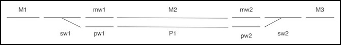
Passing Siding Electrical Segmentation
This is an illustration of a passing siding (or a station track), showing the possible electrical gaps in the track. Blocks M1, M2, and M3 are the mainline, and would be three signaling blocks. P1 is the passing siding, and could be a fourth signaling block (sometimes sidings aren’t part of signaling systems). The two switches (sw1, sw2) could be part of the mainline blocks leading into them (sw1 in M1, sw2 in M3) since a train can’t usefully pass through the switch if the lead-in block is occupied. Or they could be isolated to protect trains in M1 from electrical problems at the switch (when switches are thrown, there is often a momentary short, more on this below).
Note: no matter what, sw1 has to be isolated from both mw1 and pw1 (or M2 and P2 if there is no separate warning section), as there will be an electrical short when the switch is thrown otherwise.
Within the bounds of the siding, mw1, mw2, pw1 and pw2 are warning sections. These are needed only if you plan automated control, as a train anywhere in pw1/P1/pw2 occupies the entire siding and a train anywhere in mw1/M1/mw2 occupies the entire mainline. A warning section allows a control system to detect that a train is approaching the end of the siding, and bring it to a halt before it fouls the switch. If you just want to do signaling, mw1/M2/mw2 and pw1/P1/pw2 can be treated as two detection blocks, rather than six.
Thus, the simplest wiring for a passing siding creates four occupancy blocks (M1+sw1, mw1+M2+mw2, sw2+M3, and pw1+P1+pw2), but there could be as many as ten. Unfortunately, I want the option for automation, so I’ll have more than six, although with unidirectional running I can eliminate a couple.
Isolating Switches
A track switch (or turnout) is composed of fixed and movable rails, plus a structure where two rails cross called a frog. The movable rails are called points. In a model railroad, when the points are moved from one position to the other, the polarity (or phase in DCC) of the power changes, and this causes the two rails connected to it to change.
There are switches with electrically isolated frogs (often called “insulfrog” switches) that avoid this problem in part, although if the switch leads to a reverse loop, or “wye” track, there can still be problems. However, if you use Unitrack, the #6 turnout is not an insulfrog turnout, and thus you need to be aware of this problem and deal with it.
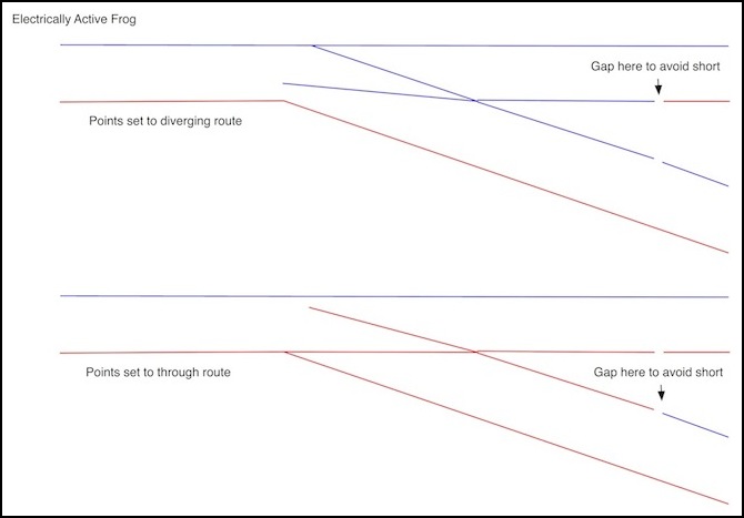
The switch needs to be gapped on the two inside rails at the trailing end (the two rails leading to the frog) as shown above. This is simply a matter of inserting an insulated rail joiner if you use the Kato switch (or other sectional track).
However, when the switch is thrown from one side to the other, there may be a brief interval where the points contact both tracks (or one track and a power feed for the other), causing a short. This is typically fast enough that it will not interfere with the operation of locomotives, so having the track on the left side (i.e., that connected to the approaching mainline block) ungapped would be okay. However, sound decoders have introduced a new aspect to this.
Sound decoders draw enough power that they may not be able to continue operating through even a brief short. What this means in practice is that the decoder will “reset”, and for many this means it will go through a startup sequence, causing the engine sound to go from normal operation to idle before resuming. Some models will also make additional sounds at startup, such as couplers connecting or compressors charging the brake line. Since these aren’t prototypical sounds for a locomotive running at speed on a mainline, this is annoying to say the least. Although I’m not aware of sound decoders for Japanese trains today, my old HO railroad suffered from this problem, and I’m going to plan to avoid it as I expect that there will be such decoders in the future.
The solution is to gap all six rails leading into the switch, and feed it from a separate circuit breaker. Since switches do not need to be part of a signaling block, and don’t have to be part of occupancy detection blocks for that matter, it is possible to feed a number of switches on separate tracks from a single circuit breaker used only for track power to switches. For problem isolation, you shouldn’t get too carried away doing that. But there are many places where several switches located together are separate, but can be combined in this manner. For example, a double-track station with two passing sidings plus a cross-over has six separately fed “switches” (counting the crossover as two, since each of the two mainlines through it needs a separate feed). Combining all of these into one non-detector power block fed from a circuit breaker separate from those used for the sidings or mainline should be fine, as shown in the diagram below (OD = Occupancy Detection).
Note: in practice, I did things a little more simply that the above implies. See my Wiring Design page for details.
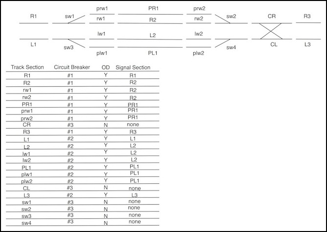
Occupancy and Electrical Blocks for a Double-Track Station
Putting it all together,the above diagram shows the general solution. This requires three circuit breakers, and sixteen occupancy detectors for full bidirectional “train control”. If I exclude the crossover and running tracks (CR, CL , R1, L1, R3, L3), then I have two circuit breakers, but each needs six occupancy detectors. Since the detectors I’m using come in sets of four on a common power input (a BDL168 has four sets of four), that means I’m going to need one four-breaker PM42, and one BDL168 occupancy detector.
But do I need to have bidirectional control? Except at the riverside station, where track design may force me to run some trains the wrong way to enter the storage tracks or subway, I’m building two-track mainlines, and Japanese prototype operation is (at least in most cases) to run uni-directionally on such track. Thus, there’s a question of what can be removed with that assumption, and whether it simplifies things. The following diagram shows this reduced design:
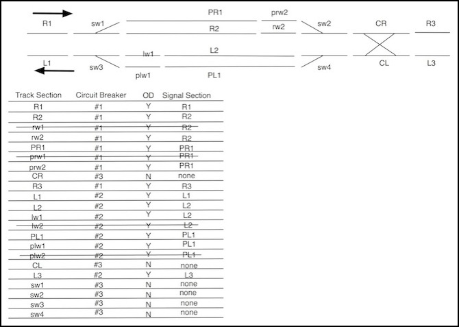
Simplified Occupancy and Electrical Blocks for a Double-Track Station
This still requires two circuit breakers (half a PM42), but only 4 occupancy detectors each. That means I use half of the BDL168. Another way to look at it is that one PM42+BDL168 can handle a four-track station with passing sidings on each track. That’s a relatively minor savings, but it will likely save me several hundred dollars on the Urban Station table.
So that’s the background for my power wiring plans for the layout. See the additional pages listed on the left in this section for further details.
References
This page was strongly influenced by a series of posts on the JNS Forum’s Layout Automation board by Martijn Meerts, although the DCC basics mostly came out of my own head (and thus from years of reading various books on the subject). I’d also spent quite a bit of time thinking about signal systems for my old (North American prototype) layout, and block detection, although I never got around to building them. But I hadn’t really thought through the control aspects, and the need for “warning sections”, albeit obvious in hindsight, was a completely new idea to me.
References:
JNS Forum Layout Automation “platform”:
Automated Computer Control - Chapter 1, Introduction
Automated Computer Control - Chapter 2, Basics of Blocks
Automated Computer Control - Chapter 3, Advanced Blocks
For additional information about block control, see:
Loy’s Toys’ Layout Wiring page is a good introduction to general concepts.
Alan Gartner’s Wiring for DCC, Block Detection page has some more technical suggestions and detail, and the Track Wiring page has a recommendation against using Common Rail wiring.
And if you want to understand signaling (even if it is mostly about North American signals), a really good book to read is:
Railroad Signaling, by Brian Solomon, hardcover, 168 pages, ISBN: 978-0760313602
a paperback edition is available as of early 2010, ISBN: 978-0760338810
Since Japanese Signaling is something of a meld of American-style “speed signaling”, and British “route signaling”, that’s only partly helpful in understanding what signals in Japan do, but it provides a solid foundation to build on.
