


The Grade Crossing
A grade crossing has always been a planned feature of my layout. Although many urban railways are grade-separated, on fills, viaducts, or in cuts or tunnels, a surprising number remain at grade, particularly adjacent to stations, where roads or pathways need to cross multiple busy tracks.
There are several distinctive elements that make a grade crossing “look Japanese” compared to western ones:
- First, the main colors are usually yellow and black rather than white and black or red and white (that isn’t universal, and Japan does have some crossings that use white as the bright color).
- Second, although they have “crossbucks” (the two boards making an “X” atop a pole), these are simply striped yellow and black, rather than having writing on them, as is often the case elsewhere.
- Third, while there are usually two circular red lights that flash in an alternating pattern, these may be mounted vertically rather than flanking the pole, and they are often supplemented by an indicator with two red or orange arrows showing the direction of motion of approaching trains.
- Fourth, while there are crossings with no arms to block vehicles, or with simple ones, the more common sight is a pair of arms on each side of the tracks, with the one blocking oncoming cars lowering first, giving cars on the tracks time to clear before those blocking the exit lower. This prevents drivers from attempting to run around the gates; a common cause of fatalities elsewhere, while allowing those who rush the gates to exit safely without damaging the arms.
- Finally, there are often signals facing the oncoming train that will light to indicate that the crossing is working properly, and others that will light to warn of an obstruction on the track (such as a stalled car), and the latter can be triggered by a manual push-button on the crossing pole (something that would only be practical in law-abiding Japan) as well as by automatic systems based on lights and photocells.
Additional important details include:
- Electrical cabinets (of the usual silver-colored metal form) and cable guideways alongside the track.
- Protective fences on the street side of any crossbucks or gate mechanisms, usually of short poles with boards between them, although sometimes of steel or recycled rail.
- Various caution and warning signs (see the example pictures mentioned below).
A page of photos of prototype crossings is available in the Scenery section.
Layout Position
There are several places on Sumida Crossing that could have grade crossings, including the Urban Scene under the station (where the subway tracks are), and the curved four-track main above the village on the River Crossing scene, but the best location is atop the riverbank where the commuter line comes off a bridge and enters the Riverside Station. Here there is sufficient room to model a reasonably complex crossing, and a good viewing position for those standing beside the layout to appreciate it, and a road there would be a useful scenic element, providing access to buildings on the hilltop overlooking the canal.
The chosen position isn’t perfect: the subway tracks run below just to one side, so access to work the crossing gates needs to be carefully planned. But it is possible. And the adjacent bridge, while making things more crowded, is also a realistic space constraint, which can be used to good effect to help form a scene.
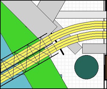
Crossing Design
The road that crosses the tracks will be two lanes (one each direction) rather than the four of the Commercial Avenue approaching it (the large gray “V” in the upper left) or the single-lane side street that parallels the tracks on the back (upper horizontal gray rectangle above). This is because it represents a through street large enough to justify a bridge over the adjacent canal and an underpass beneath the Rapid/Shinkansen tracks on the other side. This also gives a good excuse to model a four-gate crossing, which should provide additional interest if I model the delayed exit gate behavior.
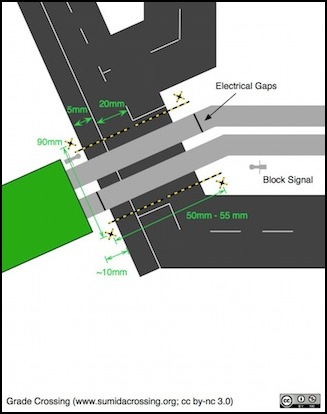
The street itself will have lanes of 3m width, which is about the minimum for a normal street with two marked lanes (single-lane side streets can be narrower, even when used for bi-directional traffic). That works out to 20mm per lane in 1:150 N-scale. There will be a sidewalk on at least one side (possibly both), of about 5mm (a scale 0.75m or 30 inches wide; a bit narrow, but reasonable, the sidewalk down to the river will likely be larger). This means that the gateposts need to be about 50-60mm apart flanking the road.
So the crossing will feature four sets of crossbucks, each next to a crossing gate. The gates will be lowered by a pair of Tortoise slow-motion switch machines (Circuitron part 800-6000), each Tortoise driving two gates via a Remote Signal Activator (part 800-8100). At least two, and probably all four, of the crossbucks will be equipped with alternating LEDs (driven off some kind of oscillating circuit, TBD) and, if I can make the LEDs fit, a sign box with a pair of directional arrows will be equipped on the post facing each entry lane. A DS64 stationary decoder will drive the two tortoises (see below).
The gates themselves will be made of brass stock, while the crossbucks may be brass poles with plastic details. A few signs will be added, but I’m probably going to skip the obstruction warning signal (they’re not found everywhere, and it would probably make the scene too “busy”, visually. Although I could change my mind.
Sound will be added through a small speaker and a digital recorder chip (also triggered off the Tortoise contacts), but that’s likely to be a slightly separate follow-on project, although I’m going to plan out the details up front.
Train Detection and Crossing Control
Detection of trains approaching the crossing will use the occupancy detectors of the blocks on either side of the crossing. When a train enters the approach block, the gates will come down (speed limits will need to be calibrated to the length of the block, and the block facing the adjacent station will be short and require some kind of speed restriction). When the train clears the crossing (is no longer in the approach block), the gates will go back up. The blocks thus need to have their ends adjacent to the crossing, but on different sides depending on the direction of travel (recall that these tracks are intended for unidirectional running, so the gates only need to work in one direction for each track; this simplifies the problem significantly).
One benefit of controlling this with DCC is that I can manually trigger the gates using the handheld throttle’s “turnout control” feature. This will allow me to force the gates closed if I need to make a reverse move between the staging/subway tracks of the station and the commuter line tracks, or between the two commuter-line tracks using the crossover.
There will be block signals adjacent to the crossing, placed so that a train stopped for a red signal will not block the crossing itself. The problem with this is that the gates will come down anyway. Another option is to place the block signal approaching the station on the far side of the bridge, with a short block incorporating the space between that signal and the grade crossing. The downside of this is that either the block needs to be fairly large (putting the signal back in the middle of the curve, perhaps), or there would need to be a speed restriction. Perhaps I’ll just let the gates start, then manually open them from the throttle. More thought on these options is required.
As with the planned signaling system, the control logic for the crossing will be a script running in the JMRI software, which will take action (activate or deactivate outputs on the DS64) based on detection of trains by the occupancy detectors. This means that the response time of the detector-script-ds64-tortoise system will need to be relatively short. One uncertainty at present is how quickly my older computer will be able to execute such a script, particularly once there are a couple dozen such scripts running to control signals.
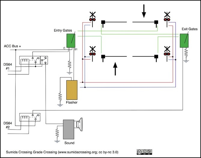
When the crossing is activated (the first DS64 output in the diagram below is set to “on”), first the lights will start to flash, the warning bell will start to sound, and the gates on the entry lanes of the crossing (top right and lower left) will close. After a short delay, the second DS64 output will be set to “on”, and the gates of the exit lanes will also close. Once the train passes, both DS64 outputs will turn “off”, the lights and sound will cease, and all four gates will rise. Not shown here, but likely, will be directional arrows on at least two of the masts, controlled by two more DS64 outputs. Essentially, one DS64 (four outputs) will be dedicated to the crossing.
Two DS64 outputs will be needed for the gates and lights, each connected to a 12V relay (the OMI-SH-212D, for example; Radio Shack sells a similar model, part 275-249 and other, similar, relays). This can be a DPDT relay, as shown here, so that it can control both gates and sound system, or the second output of the Tortoise could be used to switch power to the sound system. Two DS64 outputs aren’t strictly necessary, as a simple timer circuit could be used to delay the activation of the second Tortoise.
As the directional arrows will simply be a couple of LEDs, they can be driven directly off the DS64 outputs.
The sound system will be some kind of digital recorder (TBD) that can be programmed from a computer. A small speaker will probably be concealed in the scenery near the crossing, since a crossing warning is fairly high pitched, and doesn’t require the base response of a large speaker. Alternatively a large speaker could be mounted under the layout, but this would likely lose some directionality of the sound, although high-pitched tones can be difficult to localize.
I expect I’ll power this off the ACC bus (13.9V, 5A accessory bus), but since the power is controlled via the relays, I could just as easily use a dedicated power supply if I wanted to (e.g., if the power needs of the sound system are too large, although I think that’s unlikely for what I’m doing, or if I really need 12V exactly).
Implementation
So far this is just design, but I have most of the parts already (the Tortoises will be recycled from my old layout, and I may need to buy some small LEDs and components to make the oscillator to drive them, or just buy one like the Circuitron FL-2). I don’t expect to get to this for a while, but I needed to plan the positioning of the gate actuators and run some brass tubing through the foam and the plywood below to serve as a guideway for the actuator wire, before I glued the foam into position.
