


Prototyping and Refining the Design
I’m a strong believer in testing things out with a prototype before committing to a final design, and that’s particularly true in electronics, where I only partially know what I’m doing. For this project, I did a lot of design, and came up with my basic Simple Capacitor and Voltage Regulator circuit designs, then I built some prototypes on a breadboard (below) to see how well my theory lined up with reality. What I found was that run time was actually quite a bit longer than my conservative estimates had allowed for. While a 100 μF capacitor was shorter than I initially wanted, it was an option if I wanted a particularly low-profile design and the one I ultimately went with. The 8mm 390 μF capacitors I’d bought for my first batch of circuits turned out to be quite long-lived indeed.
Note: Larger versions of the images here can be found in the Car Lighting photo album.
Breadboard
With circuit diagram and parts in hand, it was time to build a prototype. Actually, first I breadboarded it to see if it would work at all. Then I built a prototype I could install in a car, to see how it worked on the track.
The breadboard was assembled with a 180 Ohm 2-Watt resistor to start (I couldn’t find a 2W 150 Ohm resistor locally), and also used the IC version of the rectifier (mainly because I didn’t want to use up one of the SMD ones adding wires to connect it to a breadboard). The larger wattage resistor gave me a safety margin to play with the larger capacitors (the largest of which would pull current producing slightly more than one Watt for up to 25 msec when recharging).
Using the breadboard, I tested runtime using a 2200 μF capacitor (way too large to actually fit), and found that it just kept going. Light was probably acceptably bright for 3.5 seconds, and it took minutes to fade completely. At the other extreme, the 100 μF capacitor was very brief. I’d guess it was bright for around a tenth of a second, although possibly longer. Still much longer than I’d first expected (my math had been wrong), and potentially useful to protect against very short outages, but not quite what I’d like to have given a choice. And I did have a choice, as the 390 μF capacitor would still fit in my available space (even a 590 μF one would). That 390 μF capacitor maintained an acceptable brightness for well over half a second. There could certainly be longer outages, but that was long enough for me to proceed with the use of these for my first on-train prototype.
The breadboard was also used to check heat generation. In the simple design, only the rectifier is going to produce heat (well, the resistor would if it were exposed to repeated back-to-back cycles). Using an IR thermometer (the kind you point using a laser dot to get a temperature reading) I could see that even after a half hour on my 14 volt Zephyr, the regulator was about 1.5 degrees Fahrenheit (less than one degree Celsius) above the background temperature, and the lightboard itself was less than one degree above room temperature). The capacitor and resistor were at room temperature, as far as I could tell, which wasn’t a surprise since they are unlikely to rise significantly even in normal use, and in steady-state “on” status there’s no reason for them to heat (the resistor produces less than 0.08 Watts when powering the LED directly; it only generates around 1 W when recharging the capacitor).
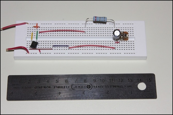
Prototype 1: the breadboard circuit
Making an Installable Circuit
With circuit diagram and parts in hand, it was time to build a prototype.
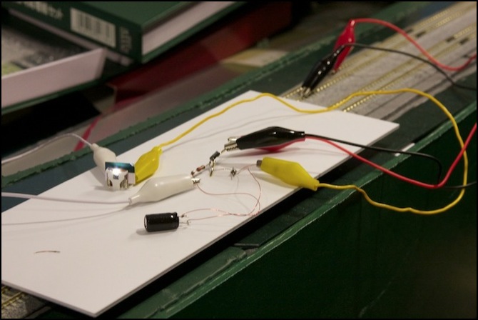
Prototype 2: a snarl of wires
The second prototype, seen above in a test on the track without a car, worked equally well. In this version, the same 390 μF capacitor was used, but connected to the smaller elements to be used in the final car: a surface-mount rectifier and a 1W resistor. I tried just soldering things together using fine wire (30 ga magnet wire), but it proved very hard to work with when soldering directly to things, and the result was a bit of a mess.
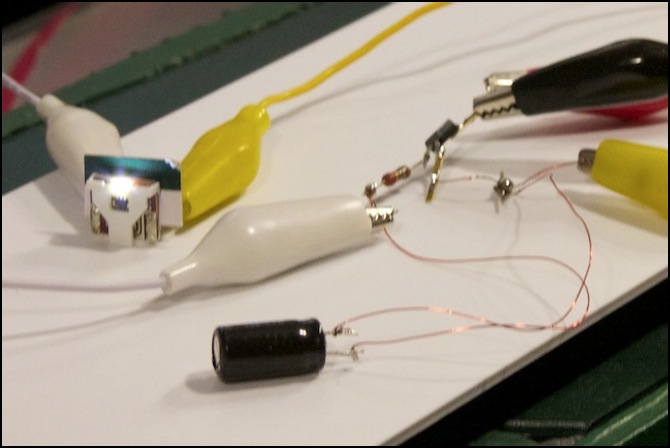
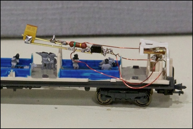
Prototype 2: close up
Here you can see the lightboard (left) with its glowing LED, the resistor (above right white alligator clip) and the adjacent rectifier, and the capacitor (foreground). The wire is 30 ga magnet wire. And the really poor level of my soldering skill is also apparent.
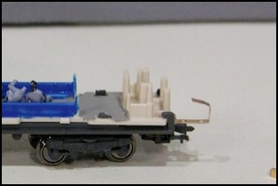
Installing this in a car required wiring it to the pickups and more permanently wiring it to the lightboard. First the pickups were bent into a semicircle (left, above). But the plastic turned out to be in the way, so the part curving towards the front was cut off, and the remaining “L” shape was used as an attachment point for the wire.
For the lightboard itself (right, above) the tabs that normally stick down and contact the pickups were bent to point forwards, with a small (~1 mm) separation from the lightboard itself, and wire eventually soldered to them.
The car was then placed on the track, where it promptly tripped the DCC command station’s circuit breaker. After a bit of thought, and a return to the workbench, I realized that in my haste to try it out, I’d connected the lightboard to the input side of the rectifier, and the power pickups to the side with the capacitor. Somehow, all of the electronics survived this mistake unharmed. A bit of de-soldering, and re-soldering in the right place, and I had a working circuit mounted in a car.
Testing the prototype by pushing the car along the track with a finger, I maintained constant lighting at normal speeds. At very slow speed, there was a slight waver to the intensity when it it a bad spot, but not one likely to be visible once the car body was added (you could see it when staring directly as the LED).
Then I pulled out the motor car and used it to push the car around at various speeds. With this, the new circuit essentially didn’t flicker at all, unless it was moving dead slow. By comparison the motor car, which I’d considered flicker-free, had a noticeable variation in its intensity. By all measures, a resounding success.
A Smaller Capacitor
While I’d been testing this, I decided that capacitor really was annoyingly large, and that I wanted to try using a smaller one. After I’d posted my original design, Don had suggested that I look at tantalum capacitors. I’d originally looked at those when I thought I needed very larger capacity, and the costs had been in the tens of dollars. But with 100 μF as an option, this turned out to be a very good idea. A number of surface mount capacitors of that size were available for $2 - $5 each, and these were small enough that they’d be much less obtrusive. Prices go up quickly from there, with 150 μF costing 2-3 times as much, so 100 μF it was. At the same time, I realized that I could simplify my soldering by using brass strip.
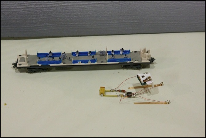
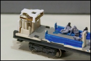
Prototype 3: assembled
Assembling the prototype went relatively smoothly, although the result was bulkier than I’d like. But part of that was because I’d made the brass strips long enough to hold a second capacitor if the storage of a single one turned out to be inadequate. The hardest part is the magnet wire, as it’s difficult to strip (I used a butane lighter to burn the insulation off) and hard to solder. I may switch to stranded decoder hook-up wire.
Prototype 3: installed
That’s obviously not a final installation, as it is too high up and would interfere with the plastic light pipe inside the car. But it was a good size for testing.
Placed on the track, this worked very well indeed. At a reasonably slow speed, a car without the circuit flickered badly, while the car with it was rock-solid. Obviously, even 100 uF is sufficient to my needs. I just need to work out exactly how I want to do the final wiring to install these, and I’ve got a working solution.
See the Movies page for a short video showing an unprotected and protected car being pushed by the motor car.
I still wasn’t happy with the assembly process; soldering to the brass strip was tricky, and the stiff magnet wire was difficult to work with. As a result of that, I switched to assembling the circuit on a bit of circuit board, see the Lighting Board page for more on that.
