


Table Construction
Construction of Sumida Crossing began in August of 2009, after several months of sketching track plans and thinking about what I wanted to include (my “want list” of features) and ran into early October. I had decided to do this as a set of flat tables may of plywood and small board lumber, with insulation foam atop them to provide scenery. This gave me a sectional layout that was portable (in a sense; I wouldn’t try taking it to a show or anything, but if I moved it could move with me).
The first phase of table construction involved just the upper deck for the two sides, and the river scene end that connects them, creating a 4’ x 12’ surface. Construction of the other end, including the helix, and the lower storage deck was to be deferred for later (well, I built the tables for the storage level). Initial track, electrical, and scenery work was to follow this initial construction. But in the end, I added the other 4’ section, to make the subway level a complete oval. The helix is still deferred.
The tables are individually constructed of 1x3 pine as 2’ x 4’ box frames using butt-joint construction, and topped with a half-inch sheet of plywood. Pre-cut and pre-sanded birch plywood panels were used, which raised the cost but provided a very smooth top for painting the river scenes, and spared me the effort of sanding them. The structure is simply screwed together, without glue, using coarse-threaded 1 1/4 inch drywall screws. I’d used #8 wood screws on my earlier railroad, but the number of screws involved in this one (there are 32 per 2x4 table) motivated me to try drywall screws, which have been reported to work well, and are relatively inexpensive. They’re not quite as strong as #8 screws, but provided a solid joint.
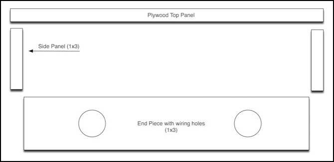
Although the plywood panels are nominally 4’ long, in practice they were about 1/8 inch shorter than that, so I made the long sides of the box structure to match. The 2’ width was correct. I actually got in trouble a couple of times where the box structure was 1/8" longer than the plywood atop it. This is mostly hidden by the foam above it, and I was careful on later tables to get it right, but there are a couple of places with awkward gaps I need to hide as a result.
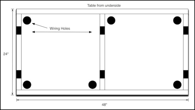
Before assembly, the cross-members (one at each end, and a central one to increase rigidity) had two 1” holes drilled, to allow wiring to pass through, rather than dropping below the table (where it would have ended up going around the support braces, making it difficult to remove the individual tables for scenery work on a table-top). The river scene tables had matching holes drilled on the sides, rather than the ends, as those tables will be laid cross-wise. Each table also had six holes drilled in the top to allow wires passing though the foam to be routed under the table. Again, the two end tables were slightly different, having only two holes, due to the plywood on one side of each being exposed by the river, and the simpler track layout used.
The wood was cut, and the wiring holes in the 1x3‘s drilled, before assembly. It took most of an afternoon to prepare all of the wood for eight tables. Assembly of the individual tables took about 30 minutes each, spread over a week of evenings, with lots of “measure twice” and checking to ensure corners were square. After that, all of the tables were drilled for the vertical wiring holes, before painting.
The tables are built to rest atop a simple framework. The framework is constructed of 2x2 legs, with 1x4 and 1x2 pine used for cross-bracing. Each leg assembly (three legs and the cross-brace and table support, located at one end of a table) is screwed together. But the leg assemblies are linked to each other via cross-braces that are attached using 1/4” x 3” bolts, nuts and washers. This allows the legs to be easily disassembled for transport. Each leg has a 1” bolt set into the bottom, which can be adjusted to level the structure. The framework wasn’t painted with primer, since its expansion/contraction will not affect the trackwork. I may paint the visible parts of it black eventually, or just hide it with cloth drapes.
When the tables are laid atop the braces, they are not attached to them. However, individual tables are joined to each other using 1/4” x 2” bolts (etc), to form a rigid structure, and there are a couple of short uprights under the tables that keep them from sliding off the cross-bar that supports them.
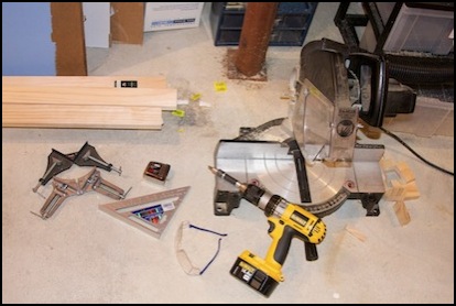
Some basic tools (L-to-R): 90-degree angle clamps, corner square, tape measure, safety glasses, variable-speed drill/screwdriver with counter-sink bit, mitre saw. Other tools were also used, but these were essential.
Construction
Step 0: prepare the wood
Since the 2x4 panels were already cut and sanded, this just meant cutting the sides and cross-bars, and drilling them. I used a 1-inch (25 mm) Forstner drill bit to cut the holes, after initial experiments with a hole saw produced very ragged results. The drill bit was both cleaner, and much faster, although messier in terms of all the shavings it threw off (a shop vac is handy, unless you like sweeping). Note that when using a Forstner bit, the wood needs to be held in place as they tend to “grab” it and spin it around. They also tend to “punch through” suddenly, so having something behind to use as a stop (I used a sheet of scrap plywood) will prevent damage to the drill bit or workbench.
When cutting the wood with the mitre saw, I first cut the existing end of the board, to ensure it was both smooth and at a right angle. I then made individual measurements, and cut, one at a time, to ensure each piece was exactly the same length (well, I tried for +/- 1/16-inch, but didn’t always quite make the cuts that precisely).
After drilling the holes, I smoothed them out a bit with a curved rasp, although this wasn’t strictly necessary.
Note that the tables forming the “river scene” at the end had different hole placement in the sides and cross-bars, as these are laid crosswise to the other tables.
Step 1: Build a box
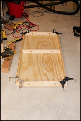
Set the sides and cross-pieces atop a sheet of plywood to position them, and clamp the four corners to make it square. I did it that way as my workbench is too small to hold a 2x4 table. You can do this one corner at a time, but it goes faster and is less prone to error with four. Working on a flat table (or sheet of plywood) is important, as this keeps the sides flat against the top; a typical cement floor is not necessarily flat. I clamp the center cross-piece after screwing down the four corners, as I only have four clamps. There are a total of 18 screws on the sides (three cross-pieces, three screws at each end).
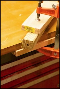
The picture above on the right shows one corner, with the first drywall screw driven in, and the hole for the second tapped. Note the beveled edge on the hole, which lets the screw top sit flush with the wood; this is done using a simple reversible counter-sink screwdriver attachment for the drill. One end has a drill bit in a tapered arbor, the other end is a phillips-head screwdriver.
Even with the corner clamps, things can get out of square (I have one table that isn’t exactly rectangular as a result). Double-checking with a large 90-degree carpenters square before driving screws is a really good idea, and I did that (eventually).
Step 2: Attach the top
First I do one screw in each of two opposite corners and check to make sure everything remains square. Then I add the others, for a total of 14 screws holding the top to the sides.
I discovered that a couple of my 2x4 sheets of plywood weren’t quite flat. Those received extra screws to flatten them out (including a screw into the middle crossbar, which wasn’t needed on most of the tables). On those tables, I didn’t use the “opposite corners” method noted above, but instead went around the outside in one direction, being very careful things remained square, to ensure the wood didn’t buckle up between screws.
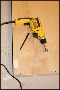
Step 3: drill the vertical wiring holes
I placed one hole near each corner, and two in the middle. These will be used to route power and turnout wiring down to the under-table electronics (DCC systems and track power bus), to avoid drilling individual holes through several layers of foam and the table-top. This will make the feeders longer, but I aim to keep them under 12”, which should be acceptable.
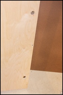
I marked the table using a small block of scrap wood to show the minimum safe distance for the centerline of the Forstner bit, then drilled by that (the pen in the left picture above points to the line, with the block of wood below it). For the center holes I marked two safety lines, for the side and cross-bar, then drilled in or near the corner they created. The picture on the right shows the finished top.
I used an AC-powered drill for increased torque when drilling. Not strictly necessary, but this kind of drilling was running the battery in the other drill down quickly (apparently I killed it, as it won’t hold a charge now; but it was fairly old and my second battery still works).
Step 4: Supporting structure, legs
The supporting structure proved to be a bit of a problem, mostly because I didn’t think it through enough in advance, and made an assumption that proved to be wrong. Unfortunately, this changed the needed length of the cross-pieces, after I had already cut them. After trying to make that work, I gave up and bought more wood; I’ll use the short pieces on other projects eventually (actually, a lot of it was used for the scenic backdrop supports).
The structure was designed to be two sections, a 4x8 unit composed of three leg elements for the long part, and a 4x4 unit composed of two leg elements for the end with the river curve (the helix end is similar). Each of the leg units is a separate screwed structure, and they are joined together using lengthwise bars (horizontal and diagonal for rigidity) using bolts, so the structure can be broken down for moves. Each leg unit on the long one has a center leg and two outer legs, supporting upper and middle cross-pieces that will hold the layout tables (there’s a photo further down). The short (river end) legs only have two legs per leg unit. On the long unit, the center leg element has two sets of cross-pieces, one for each table. Diagonal braces are added to make it more rigid. Due to the use of 2x2 legs, and the desire to maximize the strength of the joints, I used #8 2-inch screws for most of the leg assembly.
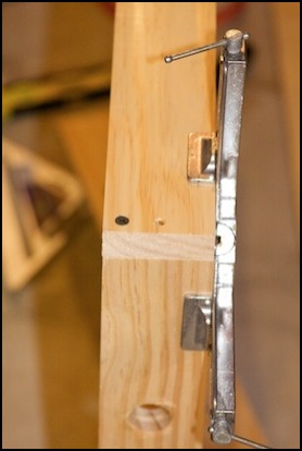
I’d planned to use 1x3 boards as legs, as this would allow the center leg to stick up between the tables, and provide both a back-stop to prevent them sliding, and a mounting point for the backdrop. Unfortunately, even the 1/4-inch bolts I used as leveling feet proved to be too large, and installing them, even with careful advance drilling, splintered the wood, as shown in the left photo below. Instead I used 2x2 posts (recommended in more than one layout construction book). The only ones I could find (other than expensive woods for cabinetry) were preservative-treated stock for deck construction. These were low quality, and several had large knots or even splits, or were seriously warped. But I found a enough 8-foot lengths in relatively good shape to make my legs. Of course, a couple of weeks later I found the 2x2 stock in the same lumber store, well hidden; I should have asked.
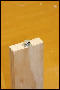
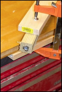
The right photos above show the 2x2 leg I used, with the hole drilled for the socket, and the socket installed (hammered gently into place with a few soft taps to seat its fangs into the wood). The feet are 1-inch by 1/4-inch hex bolts, allowing roughly a +/- 1/2-inch adjustment to level the table on uneven floors and to adjust height between the two sets of legs to exactly match.
The change of legs required me to redesign the structure. I first tried to put the outer legs outside the cross-pieces, and screw through the 2x2 into the end of the 1x4. I made this slightly easier by first attaching the 2x2 to the 1x4 using an angle bracket, which provided some increased strength and rigidity, but was mainly to hold it in place while drilling pilot holes for the 2-inch screws through the 2x2. I also had to keep the center leg top below the top of the cross-piece, as the top tables need to be 3/4-inch apart to match my track plans and the holes already drilled in the river tables. I could have changed this spacing, but I really didn’t want to. The gap between the center and outer leg is approximately 24 1/4-inches, to allow the staging track tables to fit below.
I wasn’t satisfied with the first set after I built it that way; it wasn’t as rigid as I wanted it to be, and the way the legs attached to the cross-bar seemed weak. After thinking about it for several days, I unscrewed the set I’d built, bought more wood, and made some longer cross-pieces (the 1x2 bracing was reused). These turned out much better, and once fully assembled they proved to be quite rigid, and very level. Note in the picture below the wooden blocks on the central leg assembly that keep the table from sliding off the cross-bar
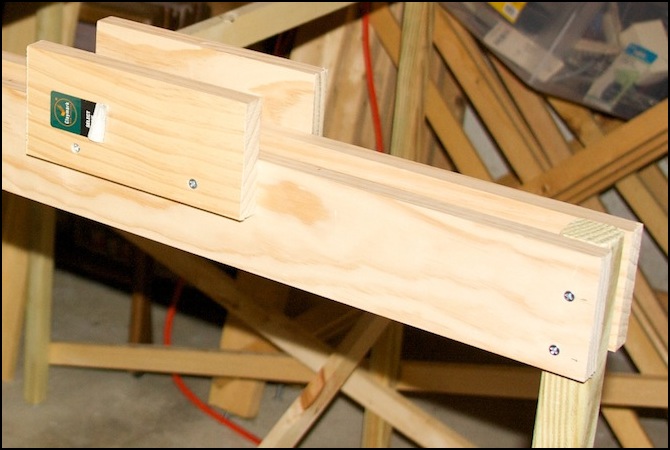
Center support with tabs to keep tables from falling off
Step 5: Paint
When completed, the tables were painted with a gray latex primer. This both seals the wood, to limit expansion/contraction, and provides a base for the later painting of the rivers. Painting with a trim roller (7” disposable foam roller) took about 30 minutes per table for a single coat of primer (I’d painted the first two with a brush, which took more than twice as long and wasn’t significantly better; actually, the coverage wasn’t as good). I did use a brush on the corners and edges of the underside, as the roller didn’t reach there. A second coat of primer went on the upper surface where it would be painted and visible.

While painting, the tables were rested atop small blocks of scrap wood atop a plastic drop cloth, to keep any dripping paint from gluing them to the drop-cloth or sticking to the floor.
Once dry (and latex takes a long time to dry properly; don’t believe what the label on the can tells you, let it sit a couple of days to dry before working with it, otherwise it tends to stick to things), the leg assemblies were put in place, and the tables rested atop them.
The four tables with rivers needed additional painting, as the wood top will be exposed and serve as the river surface (it may get additional treatment, but for now the paint will do). Water can be several colors, but I used a dark blue-green, which mimics the river water I’ve seen in some photos of the Kanda and Sumida rivers.
See the Painting Wood page for more details.
Step 6: Backdrops
Information about building the backdrops has been separated off to the Backdrop Construction page.
With the tables assembled and the backing mounted, this phase of construction was nearly complete. All that was left to do was painting the river surface and bolting the tables together (and I put in the support for the storage tables while I’m at it).
Step 7: The River Surface
I painted the river color last. After quite a bit of waffling about what to use as the basic color, I settled on a bluish-green paint (Ralph Lauren semi-gloss latex, color: “Reflecting Pool”). This came out looking quite good. It lacks wavelets (which I may add later using Woodland Scenics water or something similar), but the color is good, and on a windless day there are no waves on a river. Again using the trim roller, two coats of paint were applied to the four tables that will have exposed wood (I painted the entire surface, to simplify later work, although much of it will be under foam scenery rather than being exposed river surface). Although it “dries to touch” in a half hour, it remained mildly tacky for a long time (it took several days before something could be set on it for a couple of hours without making a noise when it was removed, and I let it dry for a week before putting anything on it and leaving it there, even then a few small pieces of foam stuck to the table-top). The trim roller actually left a texture like small wavelets, which is hard to see in photos but looks quite good in person.
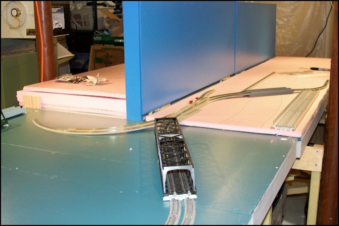
Once it was reasonably dry (24 hours) I bolted the tables together to make the six of them one unit (still just resting atop the leg structures, not attached to them other than by gravity). In the process, I discovered one mistake: I’d put the “river” end supports too close together, and one was blocking the insertion of one of the storage tables adjacent to it. Some careful repositioning and it fit, barely.
Step 8: Electronics Shelf
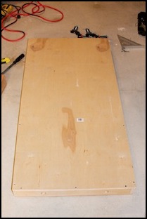
I also put a 2x4 sheet of 3/4” plywood underneath, next to one of the storage tables. This is where I’ll put the power supplies, DCC command station (and future booster), and similar stuff. I’d originally planned to build a shelf under the helix table, and I may eventually, but since that’s coming later and I don’t need a second set of storage tables yet, that’s for the future.
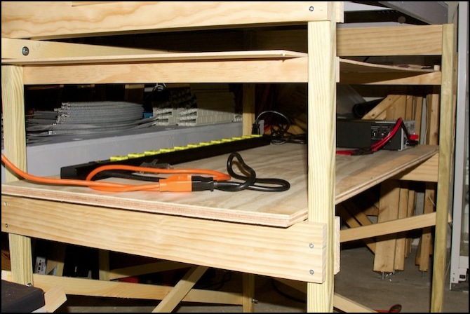
Electronics shelf front, with protective sheet above it, and gray storage shelf behind it
Above it there’s a sheet of quarter-inch plywood serving as a roof to keep anything (water, glue, paint, etc) that falls from the scenery off of anything stored on this shelf. It’s easily removed for access to the underside of the table above it. This was improvised (I had the plywood left over from an earlier design I didn’t do), but I liked the results and I later did the same to protect trains stored on the two storage shelves.
You can see one of the two storage track tables behind the electronics shelf, with some unitrack piled on it.
So that’s the basic table construction done. Total elapsed time: about six weeks (mostly of intermittent weekend work, and some weeknights). During that time I was also working on this website, revising the track plan, and working on the helix design.
With this I was now ready to start work on the layout itself, or so I thought. Instead, I'd spend several months working on refining the track plan, figuring out just how I was going to fit the subway into the "ground", and working on the lighting, but that's another story.
