


XTrackCAD
The open-source XTrackCAD program is free, and a very powerful tool once you learn it. It’s terribly complex though, and I keep forgetting how to do simple things. So this page is where I’ll keep my notes. If I accumulate enough, I may create sub-pages.
Caution: What’s written here may have changed, and in particular for installs you should read the pages linked below. I don’t install each new release that comes out, unless there’s something I need, and my notes may reflect older versions.
Installation
This program uses X Windows to display things rather than any native window manager, which works well if you are on a Linux system, but I use a Mac, and Macs no longer have a native X Windows app. There’s a solution for this, XQuartz, an open-source implementation of X Windows for the Mac that Apple continues to support. It’s functional, but limited in some respects (the present version lacks support for high-resolution “retina” graphics, although it works fine on computers equipped with such displays; it just lacks the extra pixel detail those can provide). So the first step is to download and install XQuartz, which is fairly easy as it uses a typical installer. One trick: after installing, you must reboot or log out and back in, so that it can start properly.
The remaining installation instructions are summarized on the XTrackCAD website (where you can also download the software). For the Mac, there are additional instructions linked from there, on this page. Although it was rougher when I first used it, it has now been updated and installs more directly on newer versions of macOS (I’m running on Sierra, macOS 10.12, the current version as of mid-2017).
When you launch XTrackCAD, it will launch XQuartz also (you’ll see icons for both in the dock). Then you’ll see the main window. Note that the menus for the program (“File”, “Edit”, etc) are the ones attached to the window, not the ones on the menu bar at the top of the screen (those are for XQuartz).
The main window shows a "canvas" area where the tracks are drawn, and this can be zoomed in all the way to "real size" (scale of 1:1). Lots of people use 1:1 scale to print out paper copies as a guide to laying track, once they have a good design, but since your monitor is a lot smaller than the layout room, usually you're going to be working zoomed out to some larger ratio (it starts at 8:1), but sometimes you’ll need to be at 1:1 to do things.
Although they mention page-up/page-down buttons as a zooming shortcut, the scroll wheel on my mouse actually defaults to doing that, which is more convenient.
There is a second, small, window that made no sense initially, but it turns out it's the Map Window, used to select which portion of the layout you're working on when you have one defined. Of course I closed this and later had to re-open it (View Menu, Show Map). Using it is also a bit non-intuitive. You have to click and drag the black rectangle, which shows the visible portion of the layout, to move it. You can't just click on the area you want to see, or use arrow keys.
Although the program's not fundamentally a Mac program, these days all drawing programs use similar conventions, so it's actually not that hard to figure out how to use it for the most part, although some of the commands work a bit differently from what I expected, which I'll get to in a bit, but first for some basics.
Because this is a CAD program, it's not really intended to be used "by eye". It works much better when you pay attention to the numbers. After you add a part, it switches to the "Describe objects" mode (and there’s a button if you need to switch at other times). In that mode, if you click on the part you just added, or another, you get a window full of numbers like X,Y coordinates and angles. Using these to align parts before joining them will avoid a host of problems.
One last thing: shortcut command keys use the Control key, because that's the Unix/Linux convention, rather than the Apple Command key (the cloverleaf one). So saving the file is Control-S rather than Command-S. Just one more thing to throw off an experienced Mac user who's used to the other key. Despite decades of experience with Unix, this still throws me because mostly I work in Mac apps these days.
Initial Setup
Before you start your first layout, there are some things worth doing.
The Options menu is very useful. Layout Options is probably the first thing to use. In it, you can select Scale, and while mine had defaulted to N scale (perhaps a leftover from some earlier attempt of mine to use it), there's actually a "N(JP) (1/150.0)" scale now for Japanese N. You can also set the size of the layout, and define a minimum radius and maximum grade. Finally, this is where you give the layout a name. Here’s what my test layout looks like:
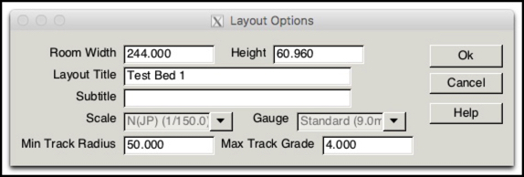
I named my Layout “Test Bed 1" and set it up for Japanese N scale. I'm working in metric and on a small test layout, so the "room size" I used was 8’ (horizontal) x 2’ (vertical), or 244 x 61 cm.
The minimum radius you set here will be enforced by the program, well, sometimes. Sometimes commands will work but try to warn you that you are out of spec. You’ll need to watch for that, or you could end up with sharper curves than you wanted. I’m setting 50 cm (19.7”) as my minimum. That’s fairly broad for N-scale, but it’s going to make passenger trains look better on curves.
Under Options/Preferences you can select English/Metric measurements, and I switched to metric since I prefer to dimension track that way. Despite growing up with English units, I find decimal measurements in millimeters, centimeters and meters much easier to deal with, particularly when I'm working on things ranging from small (track dimensions in mm) to very large (two-and-a-half-meter long station platforms).
In metric, the program does almost everything in centimeters, which I suppose is reasonable. I found this a little confusing at first, because they don't show units, and I tend to assume a metric length without qualification is in meters. Just to be confusing, millimeters are used in a couple of places.
Select Your Track
The next step is to select the types of track to use, which confusingly is done using the Parameter Files item on the File menu. There's also a ribbon bar, but it displays ALL selected parameter files, rather than just one, and doesn’t let you add files, so it's essentially useless. It's also blank for some reason, hmm, so is the parameter files window.
This turned out to be a lot simpler than I thought it would be. The files are there, but you have to load them before you can use them. To do that on a Mac, you have to Browse (using the Parameter Files item of the Files menu) to the application, and then inside it. The folder you want is:
/Applications/XTrackCAD/Contents/Resources/share/xtrkcad/params
On Linux this is just /usr/local/share/xtrkcad/params, and on Windows it's in the same folder as the application.
Once there, select the files you want, one at a time, and click Ok. You can't select multiple files together, but you can add as many as you want, one at a time.
By the way, the purpose of these files is simply to make using standard turnouts (and sectional track) easier. You don't need them for flex track itself, and you can make a turnout manually from flex track, it's just a lot of extra work.
Parameter Files
I won’t go into the details of these, the wiki’s description is fine for that. But I will comment on a few things that I found useful.
The actual format of the files is defined on the wiki's File Formats page, but they're simply ASCII text files with a non-standard ending. To view them you need to use an ASCII-safe editor. TextEdit treating the file as Simple Text will work. I prefer to use TextWrangler myself. To open this kind of file with an editor, open them by Control-Clicking in the Finder window, and selecting “Open With” and “Other”. There's not a lot of reason to examine the files, unless you plan to create your own, but it's nice to know you can look under the hood this way.
Note: work on a copy to start. Some editors will make changes and save them without warning, and that could potentially make the file unusable.
In fact, viewing this file can be very useful to see problems, although figuring out just which track in the file is the one you want can be confusing. The key is that they all have an index number as the first part of their description (e.g., for “STRAIGHT 30 4 0 0 0 N(JP) 2” the index is 30) and this appears when you use the question-mark button (Describe Objects) as part of the description at the top (“Straight Track (T30)” in this case).
BTW, my indexes start at 30 because I’m reusing an existing test file after deleting previous track. Indexes apparently don’t reset to 0 even if all the track is deleted.
Another confusing thing if you use metric is that in the parameter files, all coordinates and lengths are given in inches regardless of how they are displayed to the user.
Laying Track
Once you’re used to the conventions, laying track is fairly easy, a combination of point-and-click and fix-the-numbers.
Straight Track
Let’s start with a simple example: I want to draw two straight tracks in line and then join them.
First, select the “Create straight track” button (it will appear depressed as long as it is active), click on a spot on the diagram, drag, and release at the other end. Let’s assume you are starting at a coordinate of “2,57” and dragging horizontally to “30,57” (I’m using millimeters but it works the same for inches). Now click on the “Describe Objects” button and click on the track you just laid. You’ll see a dialog box like the following:
Oh yeah, just to be confusing, in metric the rulers at the edges of the sheet are in centimeters (so the coordinates are 5.7, 0.2), but in the Describe dialog box they’re in millimeters (so they’re 2.0, 57.0). Sloppy programming.
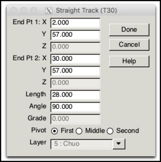
Notice how the end point Y coordinates are both “30.000”? That probably won’t happen unless you’re very careful, but you can edit one or both by typing here, to make them match. That kind of cleanup will often be required if you want to get things “just right”, although you can probably build a whole layout without using it.
Now look in the parameter file, this is what you see (along with a bunch of other stuff):
STRAIGHT 30 4 0 0 0 N(JP) 2
E 0.787402 22.440945 270.000000
E 11.811024 22.440945 90.000000
END
(pardon the blank lines; my web editor is a bit flaky)
Here the coordinates (0.787, 22.440) are in inches as mentioned previously.
Now let’s put a second track at 40,57:
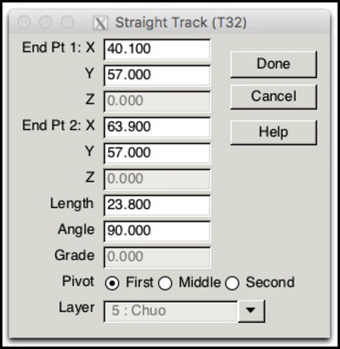
Notice the index is T32, that’s because I actually created another track first. If you repeat these steps, yours will probably be one number higher than the previous one.
This time I got my coordinates a bit off, with 40.1 instead of 40.0. However I did get 57.0 correct on both ends, which is the one that matters here. I’m not going to bother fixing the others, because it’s not needed, but you could change 40.1 to 40.0 if you really cared. However, if I’d done 57.2 instead of 57.0, that would be something to fix, for both ends, so it would be in-line with the other track.
Now click the “Join Track” button (it’s next to the “Connect Track” button, but don’t use that one by mistake). Now click on the end of the left track nearest the other track, and a red dot will appear. If you make a mistake, just click on empty background and it will deselect the button and clear the dot. Then click on the end of the right track facing the dot. At this point the program will draw a new track and join all three together and reuse one of the ordinals (in this case T30) for the new track.

If you look in the parameters file, the other track is gone and only T30 (or whatever yours is) remains, but with the endpoints of the two original tracks.
Curves
Straight track is easy. Let’s make a curve. And just to complicate things, I want easements.
First, draw two straight tracks at a 90-degree angle (one horizontal, one vertical). I used 2.0, 57.0 again, and added one 30 cm away at 60.0, 27.0 to 60.0, 2.0, shown below at a 4:1 zoom.
Now click the Easement button and select “broad” as your option. When you do, notice the value in the “R” box (44.704). That’s the minimum radius created by a broad easement (in this scale). I choose this since I’m working with large minimum radius curves also, but if you want sharper minimum radius curves, you may also want to select a sharper easement. For now, go with this and click “Ok” to close the dialog.
Now click on “Join Tracks” and then click on the right end of the top track, and you’ll get a red dot. Then click-and-hold on the top end of the right track.
Here’s the first “gotcha”: even if you do it right, you’ll see a pair of red lines between the two curves, not black. Look down at the bottom of the screen. Just to the right of the X/Y coordinate of the pointer is a text box, which should say something like “Track Radius (30.000) is smaller than the Easement minimum (44.704)”. With the minimum easement radius of a broad easement, the two tracks are too close together.
If the track are long enough, there’s a fix: hold the button down and move the cursor down along the vertical track. You’ll see the red curve move with you, and the radius listed in the box will gradually get larger. My two example tracks are just a bit too short to work with a broad easement. So, go back to the Easement button and select “Normal” (notice that the red dot remains and the Join button is still selected).
Now try again: It’s still red at the end, but pull down about 1/3 of the way, and the lines become black (around a 37 cm radius, since the minimum for Normal is 37.236). Now release the button and the tracks join, but you’ll see the straight tracks shift position slightly to accommodate the easement. However, the middle section is highlighted.
If you click on the new curve with the question-mark, you’ll see it’s actually composed of several segments. Click on the highlighted section and you’ll see that the radius is 37.351, which is below the layout minimum radius of 50.0 we set earlier. This is a warning that you’re violating your standards here, and may want to fix this.
Notice that part of the curve isn’t highlighted. If you click on one of those, it shows up as “Easement Track (T11)” (or some other index), with a radius of (in my case) 37.236. This isn’t highlighted because it’s above the minimum for a normal easement. If we change the Easement button back to “Broad” it still isn’t highlighted, because that only happens on creation. Changing minimums isn’t a way to check the layout for problems.
The curve is actually formed of five parts. The two straights, which have been shortened, the two easements, and the curved central section. When laying track, the easements can be used to gradually raise the outer rail to create a “cant” through the curve, as described on my Easements and Superelevation page.
Because I started with straights that would normally use a 30 cm radius curve to join them, I was never going to end up with a 50 cm curve that met my requirements. So you have to plan ahead when laying straight track if you want to meet a minimum radius on curves. However, I did get a 37 cm curve instead of a 30 cm curve, thanks to the easements. And those will “ease” trains into the curve more gently, which also helps. And if the two straight tracks had been longer, I could have pulled the mouse down further, and watched the curve grow into the straights until it was 50 cm in radius. It’s not where the ends of the straights are that matters, but where you join the curve into them.
S Curves
When you have two curves in opposite directions meet, they form what’s known as an “S Curve”, due to the shape. When a train car runs through an S-curve, each end of the car is being pulled in opposite directions by the couplers. Unless the curve is very gentle, this is likely to derail the car.
The fix for this is to include a length of straight track between the two curves that is as long as the longest car. For my purposes, that’s 14 cm, or five and a half inches. Easements can eliminate the need for this, with two easement curves meeting in the middle (with no curve or straight between them). This is probably not quite as good as putting in a length of straight track, but it is more compact.
While good track design can eliminate most need for S Curves, there’s one very common case: sidings. The curve diverging at a switch, followed by the curve returning the track to parallel the original track is a pair of back-to-back reversed curves. And this is a place where you wouldn’t typically have a long straight section of track, so paired easements are a good fit here, if you can make them work (one problem is that the first curve is part of a switch, so you may not be able to alter it much, unless you hand-build your own turnouts).
Another application of this, and an easier one, is where you need to widen the separation between two parallel tracks, such as when they go around opposite sides of an island platform. We’ll take this as the example here, since it illustrates the basic solution, and I’m going to have to do it quite often for my layout.
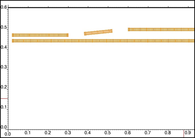
You can’t draw a reversing curve in XTrackCAD with a simple click though, it requires a bit more preparation. So, let’s start by drawing two parallel tracks. Draw the first as usual. Then select the “Create a parallel track” button, enter the separation in the box on the bottom of the window, and click on the side of the first track where you want the parallel track. Now do it again, so you have three parallel tracks. The last one added will be the “through” track that isn’t changed, the other two will be used to form the curve to the outside of the platform (you could curve both in opposite directions, if you wanted a symmertical split around the platform).
Note: I’m using equal spacing on the parallel tracks, so my final spacing will be exactly twice the start spacing. You can choose other offsets if desired.
Now, pick a point where you want to begin the curve. Actually it will begin a bit before this, so leave some space: I started 30 cm from the end of the track. Use the “Split a track” button, click on the track where you want it cut, then select the track to one side of the cut point and delete it. Now go 30 cm down the track (about a foot) and repeat this for the other track. Use Describe to check that the ends are where you want.
Now add 14 cm (about 6 inches) of track in the middle of the gap. Set the end points so that it is exactly centered left-to-right between the two tracks. Next set the vertical position so that it is slightly angled. To do that, take the offset between the two tracks, 2.8 cm in my case, and divide by four (0.7 cm). Set the end of the middle track nearest the lower track to start that distance (0.7 cm) above the first track, and the other end to that distance below the second track. In my case, the first track was at 47.2 cm, and the second at 50.0 cm, so my endpoints were 47.9 cm and 49.3 cm.
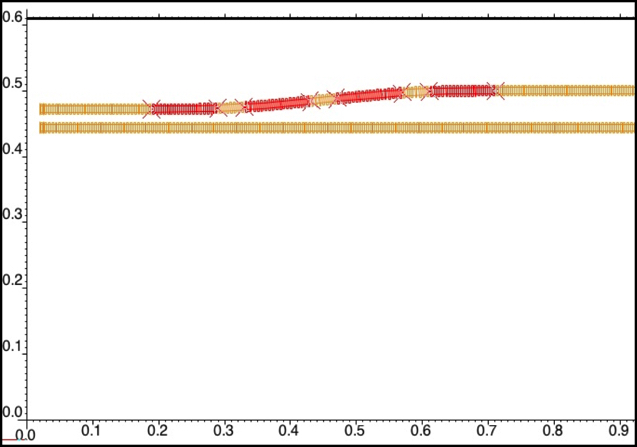
Now create a curve between the center track and the left straight by using the Join button. Click first on the left end of the middle track, then click on the left track but don’t release. Pull left until you have black lines all the way from the end of the middle track to somewhere along the left track, then release the mouse button and you’ll have your first curve. Notice that part of the middle track was removed.
If you check the track now, you’ll see that the left straight and middle straight are shorter, and that between them are two easements and a short curve.
If you find that you have only created a simple curve, rather than an eased curve, that means that the middle track end was too far away vertically, or too close horizontally. Use Undo and try changing the length or angle of the middle straight, or making the gaps larger.
Repeat this from the right end of the middle track to the right track. Now check the sections with Describe, and you’ll find two shorter straight tracks on the end, a short length of straight track in the middle, and two eased curves flanking it, a total of 9 segments including the straight track. The total length in the middle, with the straight track and the two adjacent easement sections, is 25 cm, out of the total length of 50 cm (about 18 inches), making for a very smooth and flowing curve.
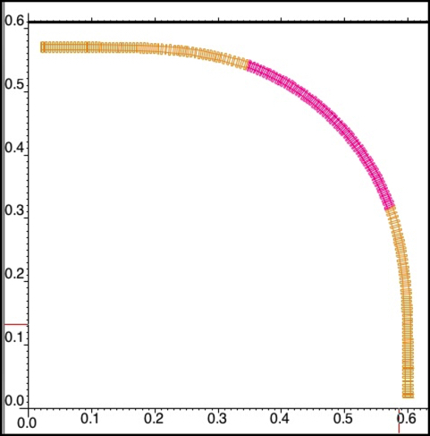
The following picture shows the finished curve, with the four easement sections highlighted.
The curves produced by this approach have a radius of around 130 cm (51”), so they are very broad, and the space required, about 50 cm (nearly 20”) is large. You could probably tighten up the spacing considerably and still have a workable curve that looked reasonably good, but you might have to use sharper easements (or omit them entirely).
Note: unlike an ordinary eased curve, you wouldn’t raise one side of the easement to create a cant, because the easement sections aren’t long enough, and it would look rather odd anyway.
