


Controller Design
The Tram Controller program will run on an Arduino microprocessor system to control two vehicles with DC motors (light rail vehicles, or “trams”). To do this it has to achieve several goals. This page lays out those goals, and provides a short overview of how each is achieved.
The goals are:
- Detect the location of moving trams using optical sensors.
- Control the motion of two vehicles using variable DC power.
- Display realistic lineside signals indicating when blocks are clear or occupied.
That’s really all there is to it, all else is just details. But some of those details are very important, and some are quite hard to achieve.
Track Blocks and Power
Let’s start with a description of the track and how it is subdivided into blocks and power is supplied to it for running trains. The track is laid out as a single track with a passing section at a station in the middle, or as double-track with stub-ended single-track stations at each end (and a station in the middle). In a sense, both of these are identical, but there’s a subtle difference in train operation. One note: as I’m modeling a Japanese line, vehicles run on the left on double track.
These two kinds of track plans replicate slightly different lines. The first is reflective of the Setagaya tram line in Tokyo, which is a double-track line with stub tracks. I’m going to use this for the light rail line in the Urban Station scene of my big layout. The second is typical of a number of rural lines, usually served by DMUs (diesel rail cars) rather than trams, but would be suitable to any lightly used line. I’m going to use this on my One Point Five Meter Line layout, because it will look better with the scenery I have planned for that. As the two work similarly, I can use the same program to control both.
There are four electrical blocks, separated by the switches. For convenience we’ll call these the West, North, East and South blocks. There are two variable DC power supplies, call them A and B. Supply A is always connected to the North block, and Supply B is always connected to the South block. But the East and West blocks can be connected to either station.
Example
In the diagrams below, tram T1 is in the West Station (West Block), about to depart on the eastbound line (North Block). To do so, West will connect to A, A will power up, T1 will run through the switch into North (still on A).
Meanwhile, tram T2 is occupying a sensor (O8 in the upper diagram, O6 in the lower) waiting at a signal (S6 or S4). The signal will be red while T1 is in the West station.
As T1 departs, first it occupies sensor O1, which does nothing, then it occupies sensor O2. When it clears O2, then the West block is known to be clear. While T1 trundles down the Eastbound line, the West station has its power switched to supply B. Then the signal (S6 or S4) is changed to green, and power on supply B is ramped up from zero. Tram T2 proceeds through the switch and down the track until it occupies sensor O1. At this point, T2 is gradually braked to a halt in the West station.
T1 will continue down the track until it reaches sensor O3, where it will be braked to a halt and held at the platform until a “wait at station” timer expires. At this point the two layouts act differently.
With T1 at North (and T2 still in West) in the upper diagram, signal S2 will change to green when the timer expires, supply A will be ramped up, and T1 will proceed to O4. If S3 is green, it won’t be held and will proceed into the East station (which was switched to supply A before S3 was set green). Until T1 clears S4, the North block is considered occupied, and S1 will be Red. T2 will remain parked at West station. Once T1 is parked at East station, East station can be set to supply B. West station can be set to supply A. Then S1 can be made green, and T2 allowed to depart.
However, in the lower diagram, there’s only enough track in North and South blocks for the tram to sit at the platform. Thus even after its timer expires, A tram (T1 in this case) will remain parked at north until East station is ready to receive it (i.e., can be switched to supply A). Once it is, signal S2 goes green, power is ramped up, and T1 runs down the track until it occupies the detector O4. From there, the same behavior follows to part the tram and release T1 from West station.
Trams will always remain at a platform for the time set by the “wait at station” timer, and may be held longer if their signal cannot be changed to green. Because a tram will always be kept from entering a single-track section until the other tram has left it, the two will stay roughly on their own halves of the layout, passing only in the middle. But the upper track plan allows them to run past each other in the middle, rather than simply both parking at the station to pass.
By changing the duration of the “wait at station” timers somewhat, the two won’t synchronize to chasing each other closely. This aspect is more important in the upper diagram.
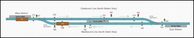
Layout with long double-track: 6 signals, 8 sensors
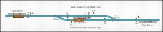
Layout with short double-track: four signals, 6 sensors
Power
I’m using DC power, since I don’t need anything fancy like DCC. The Arduino will be equipped with a “Motor Shield” that contains two variable DC motor controller circuits. This will be hooked to a 12V DC power supply capable of providing 600 mA total power, more than enough to run two N-scale trams. Motor shields for the Arduino provide variable DC using Pulse-Width Modulation (PWM), which is the same way a DCC decoder provides variable power to a motor in a train using the constant-voltage it gets from the rails.
The Arduino will be programmed to provide PWM at high frequency (32 kHz), which avoids any problems we might have with small vehicles using open-core motors and also will run quieter than the Arduino’s native PWM frequency of 500 Hz (which isn’t at all suitable for model trains).
Track Switches
It’s worth noting that I haven’t said anything about throwing the switches before the trams go through them. That’s because I don’t need to. I’m using a type of Tomix Finetrack switches that act as “spring switches”, a feature common on real-world light rail lines. The switch is set for one direction, so a vehicle entering from the point side (one of the end stations) will always take the same route (here I have them set for the straight route, rather than the diverging route). But a tram running into the switch from the other route (the diverging route in this case), will simply push the points out of the way and drive through it. This kind of switch has to be specially designed, both so the points can be pushed out of the way without derailing a light car, but also electrically, so doing so does not cause a short the way it would with a normal track switch.
Sensors
To know where the vehicles are, I need some kind of sensor. I’m going to use simple InfraRed (IR) photodetectors. These are cheap and don’t require any modifications to the track or trains. A light source (and IR LED) is set up on one side of the tracks, shining into a photodetector on the other side at a height where the train body will block it. Normally when the photodetector is read, a high number is returned (because of the light shining on it). When a train is blocking the light, a low number is returned.
The program to deal with the sensors needs a degree of complexity, to deal with the fact that the actual numbers for light and dark can vary due to other light sources in the room (many kinds of light fixture,as well as sunlight, produce InfraRed light). It’s also important not to falsely detect the sensor going clear because of something like a transparent door or window on the side of the car moved past it, letting light through, or the same from a gap between cars if running a paired set.
All of this is handled by doing some “smoothing” to ignore brief changes, using hold-down timers to avoid changes happening too close together, and adding some adaptive code to recognize when all of the sensors have changed together because the room lighting changed.
Packaged together, that gets me a sensor that reliably reports “I’m occupied” or “I’m clear”. The program needs to add another layer of control, as once a train passes a signal, that track block must be remembered as occupied long after the sensor is no longer occupied, until some other sensor is occupied, so there’s going to be a concept of track blocks being occupied that is influenced by sensor changes, but isn’t directly tied to them.
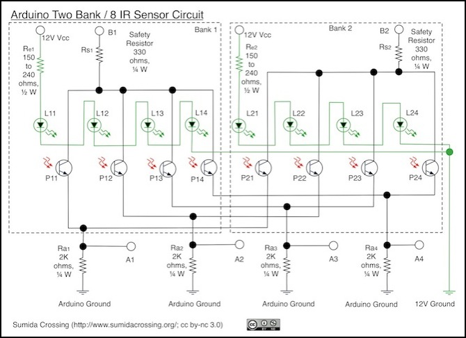
Sensor Design for 8 sensors
Signals
The signals really just provide a visual summary of track block occupancy, except that they’re also forced to be red if the “wait at station” timer hasn’t expired yet. The function of the Arduino to operate them is a bit complex however.
The signals I plan to use are New Jersey International N-scale LED signals. These will have their anodes (positive side) wired in banks of two to an Arduino digital pin. As I’m using charlieplexing to drive the LEDs, each pin will also connect to the cathode (negative pin) of several other signals. When the anode pin is set as an output and high and the cathode pin is set as an output and low, the LED will light. If either pin is set to the other state, or is set as an input (“high impedance”) pin, the LED won’t light. With this I can light two LEDs in the bank simultaneously (I could light all four, just barely, but my signals don’t need both red and green lit together).
But I won’t just turn the on and leave them on. Instead I’ll keep a list of which signals need to be red or green, and cycle through the banks. Only one bank will be on at a time, and in that bank I’ll set the pins to turn on the appropriate LEDs. Then, a few milliseconds later, I’ll turn the whole bank off, and move on to the next bank, cycling through all the banks quickly and repeating the process.
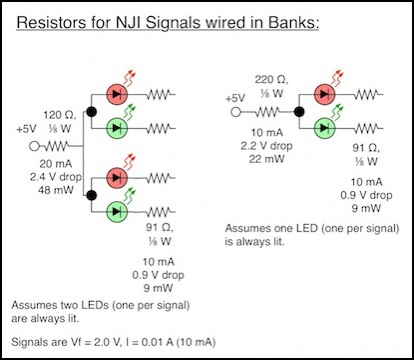
While the signals appear to be continuously lit, in reality they are pulsing on and off at a fairly high rate (about 2 milliseconds on and 6 off for each “lit” LED). This allows the 12 or 16 LEDs to be driven using only five pins on the Arduino (12 could actually be driven with four pins, if I wanted to make that version even more optimized). And since only two LEDs are lit at any given time, this only requires about 20 mA total from the Arduino when using small SMD LEDs, which is well within its ability to provide. Trying to drive eight of the 16 LEDs continuously, aside from requiring 16 pins, would require 80 mA of power, and while possible that’s more load than I want to have. I could also use a “LED driver” circuit to drive them, but that’s more electronics and I’m happier trading software for hardware.
Actually making this work requires that some care be paid to timing within the Arduino’s program. I need to make sure that each set of LEDs is lit for about the same time (so they’re equal in brightness) and that each LED gets lit once every so many milliseconds (so they appear lit rather than flickering). The magic number turns out to be 8 milliseconds because of the way video cameras work. And to do that, I have to make sure other things the program is doing don’t take too long, and that means breaking some of them up into sections and doing each section separately, which makes the program a bit more complex.
Controls
There’s not much more than “run” and “don’t run” to controlling this. I could use just one switch so that the trains don’t start moving as soon as I plug the layout in. Instead, I’m going to have a “run”/“stop” switch for normal operation plus a “run”/“emergency stop” switch. The difference is that “stop” will let the train run until it blocks a sensor; a good parking point for swapping one car for another or turning the layout off. The “emergency stop” will just cut power to the track immediately, as a way to deal with derailed vehicles, objects on the track, or similar problems.
And one last touch is that there needs to be a way to set top speed for a train, since two vehicles given the same voltage won’t run at the same speed, and it would be good to have both cars running at similar speeds. It’s also important to have those speeds be “light rail” speeds rather than the “jet fighter” speeds some N-scale trains will achieve at 12V. There aren’t any light rail lines that I’m aware of running at 250 kph (about 150 mph). So I also have two potentiometers, which will be associated with “tram A” and “tram B” (which is more complex than it sounds, since which power supply is used for each will change as they move about).
Control Logic
The actual program to run the train, once you get past all the complexity of sensors and LED-driving, is really quite simple. The change of sensors from open to blocked or blocked to open causes most things to happen, marking track blocks and stations as occupied or available, and causing train throttles to be set to half speed when approaching a station or stopped within one. The only thing they don’t do is start the trains once they’re stopped at a station. For that a timer is used, started when the occupancy detector parks the train. When the timer expires, the train can’t proceed unless the block ahead is clear, but once that happens (the other train moves out of the way and an occupancy detector clears the block), the expired timer causes the train to start moving.
The reason the occupancy of both stations and track blocks needs to be recorded is that they aren’t identical. Track associated with a station may take seconds to traverse before the train enters the station itself. And blocks need to be marked as occupied as soon as a train enters them, to prevent a following train from being started prematurely. But detectors at the station may be occupied as long as the train is in them (North and South stations) or crossed twice (East and West stations), and the interpretation of the occupancy detector events depends on knowing if this is the first event caused there by that train, or a later one.
Startup is a special case: we don’t know where the trains are. At start, the trains are run at half-speed until they hit a detector, and stopped as soon as they occupy or clear one. Power at the two end stations is set to run towards the middle of the layout, so trains won’t run into end-of-track buffers if they stated inside the end stations. This could result in both trains running on one of the power supplies, and both stopping when the first is detected. If that happens the second can’t be detected, and some special logic will be kicked off by a “deadman” timer eventually, to restart both trains (now knowing the location of one) until the other hits a detector. At that point, the trains will be run until one is inside an end station, and can be switched to the other supply.
This could fail, if both trains started close enough to each other that both are in the same end block when the location of the second is determined. Avoiding this condition is one reason for having a run/park switch, as it will place both trains in a “good” (separate and easily detectable) location before turning them off.
