


Using Servos On A Model Railroad
A servomotor, or servo for short, is a self-contained motor, controller, and reduction gear system in a box. Rather than turning continuously, most of them have a limited range of movement, and are normally configured to move a lever from side to side and hold it in position. If this sounds a lot like the kind of stall-motor we’ve been using to throw turnouts on model railroads for decades, that’s because in some ways it is very similar. There are differences, and two of the most important are economy of scale and how they are controlled.
The newer micro servers are particularly interesting, because they are very compact compared to current motor-based turnout controls, and are thus suitable for more space-constrained environments. And yet they have sufficient power for throwing typical turnouts, as well as being applied for other purposes such as crossing gates (or semaphore signals for that matter). They are also potentially less expensive (if you are willing to work on your own control system; commercial systems are still somewhat expensive).

Micro Servo with Four-Arm Horn (shown larger than actual)
Photographer: oomlout (via wikimedia)
Servos have been in use by non-railroad hobbyists for decades. They’re in nearly every radio-controlled toy ever built, and in recent years the hobby of robotics has created new users. All of that means that servos are manufactured in volume by competing companies, and that helps pull prices down. A typical micro-size servo with nylon gears like the one shown above will cost under US$5 in bulk; some cost considerably more, depending on what you need them to be capable of doing.
They do, however, require specialized controllers. You can’t just wire a switch up to one to make it work. A simple analog timer circuit can be used, but in recent years with the rise of inexpensive embedded-processing computers, like the Arduino, new options for control have opened up. The Arduino software comes with a built-in servo control library, and there are external shields and circuit boards for powering servos while controlling them from the Arduino.
A servo is not a stall motor though, and treating one as if it is can destroy it. Like any device they have their strengths and weaknesses, and to best use them, these need to be understood.
Uses in model railroading include throwing turnouts, raising and lowering crossing gates, positioning turntables, creating animated scenes by operating things like doors or moving spouts on steam railroad water tanks, etc. Turnout control tends to be the most common application, due to potential cost savings and because it is relatively easy to do. See this blog post for information from someone with several years of experience using them for a large yard (the system described eventually became the MRServo product, but there is useful information in the post even if you use another system).
Obviously servos, like stall motors, aren’t appropriate for turnouts that use built-in electro-magnets to throw them (i.e., the usual Kato and Tomix turnouts). You could modify either to remove the electromagnet and use a servo, but it would be a bit of work. They work very well indeed with turnouts designed for external motors.
Basics
A servo is a fairly compact device, the smallest are about 1” x 1 1/4” and a half-inch thick (22 x 12 x 30 mm). There’s a toothed output shaft (called a spline) on the outside, attached via a shaft to the internal reduction gearing, and it is used to drive a lever or other moveable structure (called a “horn”) attached to it; the four black arms in the photo above are a horn. Three wires connect to the servo, ending in a standardized plug. Inside the servo, in addition to the reduction gears are a small circuit board, a potentiometer for reading the servo position, and an ordinary DC motor.
The spline used on the servo’s output has teeth that engage on the inside of the horn attached to it. Different manufacturers use different tooth counts, so horns are specific to a manufacturer. Horns are held on by short screws that lock them in place.
Most servos have a limited range of motion. While 180° (+/- 90° from a center point) is commonplace, many have a shorter range (90° is fairly common, and many will do 180° with specialized controllers and 90° with normal ones). There are some than can rotate continuously (such as for operating wheels on a robot), but these are designed somewhat differently from normal ones. It is also possible to modify many limited-range servos to be continuously-rotating ones, although some trade-offs have to be accepted when doing this since the servo isn’t likely to have been designed for that purpose.
Servos almost always operate on 5 volt power, since this is a good fit for modern control systems using digital circuitry. They are rated for a range from about 3 to 6 volts, and many will work on typical 7.2 volt L-Ion batteries, even if technically overloaded. The three wires are + (usually +5V), ground, and a control line. The use of 5V power means they need a special power supply (you can’t wire them up to the 12 or more volts used for typical railroad accessory power). Normally the ground wire will be black or brown, and +5V wire will be red, and the control wire will be orange, white or blue (but other colors may be used, consult the documentation for the specific servo if in doubt).
The power and a control line are connected through a connector, and the convention among RC hobbyists is to refer to this as “male” and to refer to the shrouded male pin connectors it attaches to as female. However, per this site the “male” end is a plug with three female sockets, and the “female” end is actually a set of male pins hidden within a protective shroud. Both use pins and sockets on 0.1” (2.54 mm) offsets. That means the cable from a servo can be plugged onto a 0.1” spacing male header on a circuit board, which is often what control boards are provided with.
The connector on modern servos always places +5V on the middle pin, so it can’t be mistakenly connected to one of the others. However is it possible to reverse the plug and connect the control line to the ground wire on the servo. This could potentially be very bad for a microprocessor-based controller (see the notes further down about placing a safety resistor on the control line).
Servos do not draw continuous power, but instead use a series of short pulses 1 - 2 milliseconds (ms) in length spaced about 20 ms apart. This means that their average power draw is considerably less than their peak power draw. And the peak current for even small servos can approach (or exceed) 1 Amp.
The power used by a servo also doesn’t depend on whether or not the servo is moving. Instead it depends on the force against which it is pushing. A stationary servo with no load draws very little power. A moving servo under light load draws a moderate amount, and a stopped servo with some back-pressure will draw more. A servo pushed all the way to its limits will be stopped by a tab that blocks further motion, and in that position the motor is stalled and will draw its rated stall current (the maximum power it can draw). If this is maintained for too long it may burn the motor out. The same will also happen if the servo is not at its limit of motion, but is prevented from moving further by an external force. The servo will keep pushing at its maximum output, drawing the stall current.
A servo at these limits will also tend to be more noisy than one in motion, because it is continuously stopping and restarting to push against full load, causing the internal gears to engage and disengage dozens to hundreds of times per second.
Servos move very quickly, going their full side-to-side range as quickly as 0.3 seconds, although the controller could be designed to slow them down to a more realistic speed for railroad use. This is normally given as a rating for motion through 60°, so one that can move 180° in 0.3 seconds would be rated as “0.1s/60°”.
The bottom line is that servos are designed to quickly position things within their range of motion and keep them there, not to continuously work against a load the way a stall motor (or a typical DC motor for that matter) does, or to move slowly. You can do both, to an extent, but it is important to consider the limits of the servo’s design before doing so.
Types of Servos and Characteristics
The servos most commonly used for model railroading are “analog” servos rather than “digital” ones, which sounds odd since they need to be controlled by a digital circuit, but in this case “digital” has a specific meaning, and isn’t the one we want. A digital servo has a more complex (digital) internal control system. They’re capable of reacting much faster, holding position better against external forces, and applying more force (torque). They are also more precise, meaning that they have a smaller “dead band” (see below). However the cost of this is that they consume considerably more power (often several amps, where a normal servo has a stall current of at most a few hundred milliAmps). All of this also means that they have a significantly higher cost.
Another way to compare digital versus analog is by reaction time. Normal hobbyist servos expect a control pulse 50 times a second (once every 20 milliseconds). For analog servos, this is also how often they react to changes in position due to external forces. Thus they can’t react any faster than 20 msec if something pushes them out of position. A digital servo can react much faster, since its response time is not related to the input cycle. A typical internal speed is 300 - 400 Hz, meaning they can react in 3.3 milliseconds or less.
All of that is nice, but not necessary for most applications on a model railroad.
For our purposes the most important rating for servos is their torque (output force). This is normally described as the stall torque, the force against which the motor will stop moving. Stall torque is usually given in kg-cm (sometimes erroneously written kg/cm, but it’s a product). Sometimes it is instead given in oz-in. There are 14 oz-in to one kg-cm if you need to convert. If torque is given as two numbers, the first is usually for 4.8v and the second for 6.0v. For throwing turnouts, a stall torque around 1.6 kg-cm (22 oz-in) is more than sufficient, and almost any servo of micro size or larger can provide this.
Keep in mind that torque converts to force based on the length of the lever used. If you connect a turnout throw rod to a 1.6 kg-cm servo at a distance of 2 cm from the servo’s axis of rotation you get 0.8 kg of force, not 1.6 kg. This is also affected by other levers, such as the placement of a pivot point. If a turnout servo moves the end of the rod at the servo 2 cm, but the pivot causes the other end to move just 0.5 cm (as it might for N scale), then you have multiplied that 0.8 kg by a factor of four, to get 3.2 kg. Positioning of servos and pivots can thus make a lot of difference in the effective force at the turnout (or other device). Even without a pivot, these servos put out a lot of force, and properly mounted they can deliver several kilograms (many pounds) of push. They’re really over-powered for most applications.
Operating range, given in degrees, is another important characteristic. This may be given either as a total to both sides (180° means 90° to either side of center) or as a pair of offsets from center. The total range required in most applications is less than 180°. For turnouts, the required range depends on both the track gauge (HO needs more degrees than N because it has a larger throw distance), the distance from the track to the servo mounting (further away means fewer degrees), and exactly how the turnout is connected to the servo.
Servos are classified by size and their weight in grams. There are many possible sizes (sub-micro, micro, mini, park, standard, X-large), but the micro, standard and large sizes are most common. The weight in grams is used as a rating because they’re often used in airplanes, where weight matters more than size. Both have an approximate relation to power, but only roughly. The micro servos are small, about 1/2” (12mm) wide, and 1.25” (32 mm) long and tall. The standard size ones are slightly larger (2” x 1.5” x 3/4”, 50 x 36 x 18 mm). One very common servo type for model railroad use is the “9g micro”, which is small, inexpensive, and has enough torque for most applications.
The built-in reduction gears can be made of nylon, metal or an in-between fiber compound (sometimes called carbon-fiber or by various brand names). Nylon gears are white, while fiber gears appear normally to be black (or possibly gray). The choice of material depends more on the force that will be provided; even nylon gears will last a long time in normal use. Cheaper servos will likely have more play in the gears, which equates to more noise in operation. On many servos the gears can be replaced if they do wear out. Metal gears can deliver more force with less wear on the gears, but this isn’t likely to be an issue in most model railroad use.
Some more expensive servos have bearings, but most simply have a plastic shell that holds the drive shaft in position. Again, this is likely sufficient for most and perhaps all model railroad applications.
Servos also have a characteristic known as a “dead band”, which is effectively the positioning accuracy of the servo’s control mechanism. When a servo stops in a position, it can move within the dead band without the controller restarting the motor to correct the position, and it could have stopped anywhere +/- half the width of the dead band from the desired position in the first place. Dead bands are described in units of time, not position (e.g., 10 microseconds is a typical dead band for an inexpensive servo). Smaller dead bands are more accurate, but may result in the servo running more often due to small deflections that don’t matter.
A typical hobby servo uses a pulse variation of 500 microseconds to move 90°, so a 10 microsecond dead band is 1/50th of that, or 1.8°. That’s precise enough for many things, but not everything. Some “high performance” servos can have a dead band as low as 1 microsecond, which would equate to 0.18° (assuming a 90° deflection). Some servos also have lesser maximum deflections for the same signal, which equates to more precision (at the cost of less operating distance).
Servos also have a power requirement (this is from the +5V wire, not the control wire). Sometimes an “idle” or “operating” current is given, which matters for battery use, but not otherwise. Normally model railroad applications use wall-current, so sizing the power supply for maximum load is all that matters. For that you need to know the stall current, as this is also the peak current drawn when moving to position (it’s a short-term peak, though, more on this in the power supply section). Some servos don’t have documented stall currents, but there is a nice list at this site for some of those.
Peak current can be higher (as described by someone who measured a number of servos, on this page).
Continuous Rotation
Normal servos have a limited range of motion, but there is a type of servo called a “continuous rotation servo”. These however, are specialty devices. The standard hobby servo interface does not support rotation with feedback, and feedback is what is needed for “closed loop” control over a continuously-rotating motor (and closed loop control is what makes a servo a servo, it’s just that on limited-range servos, this happens inside the box).
There are, however, position-controlled motors without feedback control, called “stepper motors”. Another differentiating factor may be power use. Some stepper motors will draw power continuously when holding position (likely due to having a very narrow “dead band” to avoid cumulative positioning error due to the lack of feedback).
Unfortunately, usage of this terminology online is sometimes lax, and you can find lots of things called continuous rotation servos that are simply ordinary servos modified to use open-loop control (which isn’t feedback control). These still have position control, making them a stepper motor, albeit probably not a very precise one. However, you can add a feedback mechanism to a stepper motor or a continuous-rotation motor made from a servo.
Assuming that there is feedback control, this takes two forms: potentiometers and rotary encoders. A potentiometer is less accurate (although software can compensate for that to an extent) and will wear over time. Rotary encoders are better, but are typically more expensive than a potentiometer.
Internally, all servos have some kind of position tracking (usually a potentiometer on inexpensive hobby servos), but this is not accessible from outside. It is used by the internal control board.
Force and Distance
A servo’s output is a rotating lever, called a horn. The horn can come in many shapes, and can also be a gear, but for most uses it can be thought of as a lever of some kind. Servos provide an output torque, which is simply the product of a force and distance from the axis of rotation. Change the distance, and you change the force. If you don’t want to work through the examples, skip down to the bottom of this section for some conclusions about how servo mounting choices relate to throw force on a turnout tiebar.
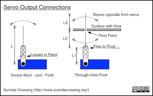
For example, in a simple back-and-forth arrangement (see diagram), where a stiff wire is rigidly attached to the servo horn, when the servo turns 30°, the end of the wire moves 30°, but it moves a much further distance, so intuitively you can see that this provides less force as it moves (because the same force is distributed over more distance). If the servo’s torque is 1.6 kg-cm, that means that it pushes with 1.6 kg of force (56 oz) at 1 cm (about a half-inch) from the center of the spline on the servo. To calculate the force at any other distance from the center, you simply divide 1.6 by the distance in cm. So if the wire is 5 cm long (about 2”), it’s pushing with 1.6 / 5 = 0.32 kg at the end (about 11 oz’s). That’s actually fairly strong, which is why micro servos mounted to the underside of subroadbed can throw most turnouts without any added complications. But if you need more force, or have a weaker servo, there is a way to address that: allow the wire to pivot at its point of attachment to the horn, and provide an additional pivot point closer to the track.
If you add pivot points, you are creating a set of levers laid end to end. And levers can be used to magnify (or reduce) force. Again there’s a simple relationship with distance, but this time it is based on the distance of the ends of the lever from where the lever is pivoting (the “fulcrum”, to be technical). For our “pivot” example below, the formula for this is F2 = (F3 x L2) / L2 (where Fn is the force at distance Ln from the pivot).
In the pivot example below, the wire is run through the horn and hooked to the side, so it doesn’t fall out of the horn, but is free to rotate. This creates a lever (L1) whose distance is that from the spline to the point where the wire connects to the horn. Then the wire runs through a small hole (say, the top of the layout), which provides another point of rotation, and the distance from this to the horn attachment is L2. The force at the end of L2 nearest the servo is the same as the force at the end of L1 (it’s the same place, so it must be the same force).
Finally, the wire runs up through the surface to where it is pushing on something (like a turnout throwbar), and this distance from the pivot point between L2 and L3. Now L3 needs to be long enough that the end will move a useful distance, so the pivot point is probably best made at the underside of the layout surface (e.g., by attaching a metal strip with a hole drilled in it). This could be lightweight brass unless you plan to apply a lot of force. L2 and L3 make up a second lever, pivoted in the middle. The ratio of the two lengths determines how the force changes from one end to the other.
Let’s start with L1 and use 1 cm as that distance. At 1 cm from the center of the spline, the force is 1.6 kg-cm / 1 cm = 1.6 kg. That means that at the lower end of L2, we have the same force. Assume L3 has to be 2 cm to reach from the pivot (the metal plate) to the turnout tiebar it is throwing. If we make L2 also 2cm, then the same force is applied at both ends of the lever, and we’re pushing on the turnout arm with all 1.6 kg (56 oz), rather than the reduced force we saw from the simple back-and-forth example. You can magnify the force by making L2 longer, but then the servo horn has to move further to move the upper end of L3 the same distance (that extra servo rotation is where the extra force comes from).
So examine the two cases. Assume the layout surface is 2 cm thick (1/2” subroadbed plus some roadbed). And assume the servo needs 1.5 cm from the underside of the layout to the spline, which puts the wire 0.5 cm below the layout surface. In the lever case, with the servo attached to the layout, the force at the turnout is thus 1 / 2.5 times the output (2 cm of layout plus 0.5 cm to the end of the wire at the servo), or 1.6 / 2.5 = 0.64 kg (22 oz). This should be enough to throw most turnouts, unless they use very stiff springs. So a simple, close mount without any complexity will work reasonably well.
There’s a problem with this, as it has the horn moving into the subroadbed if the servo is actually mounted flush to the underside of the layout. Ignore that for now, we’ll fix it in a bit.
But suppose instead we mount the servo 5 cm (2.5 in) below the layout and attach a pivot to the underside of the subroadbed. Now L3 is 2cm as before, but L2 has become about 4 cm. The servo arm will need to move twice as far as the turnout throw distance (which may be impractical for larger scales with a micro servo and standard arm). But the force applied with be multiplied by a factor of 2 (the ratio of L2 to L3), or 3.2 kg (112 oz). That will throw any turnout. The only risk is that it may be enough to push the track out of position if the distance of motion isn’t properly calibrated to stop when the point rails touch the stock rails. These micro servos are actually very powerful.
Note that if you can’t get this to move far enough, and extend the length of L1 with a longer horn, you’re doing two things: first, the force acting on the wire depends on the new length of the horn referenced to 1 cm, so if you use a 2cm horn, you’re only getting 0.8 kg on the wire at the end of L1 (1:2 ratio). Second, if you left the servo 5 cm below the layout, you’ve removed 1 cm from L2, which makes the new ratio for it 3:1 rather than 4:1, so the force applied at the turnout is now 3 x 0.8 = 2.4 kg (85 oz) rather than 3.2 kg. That’s still quite a lot, but as you can see, making the servo arm longer has reduced the useful force (assuming you keep the mounting distance the same).
Now, I’ve drawn the above diagrams with the horn of the servo pointing towards the direction of the wire. Often servos are mounted flush to the underside of the layout with the horn pointing down, and the wire runs along the horn, past the spline, and up through the layout subroadbed. How does that change things?
In the “locked” example, the wire, like the horn, continues to pivot about the axis of the spline, and there’s no change at all. The fact that part of the wire extends down past the pivot point is irrelevant. What matters is the distance from the center of the spline to the end of the wire we care about.
In the “pivoting” example, L1 remains the same, but L2 is now the total distance from the underside of the layout to the pivot point on the horn. If you assume the servo is mounted to the underside of the layout in the same manner as in the “locked” example, and the pivot hole is on the underside of the layout, then L2 is the thickness of the mounting plus half the thickness of the servo (or about 1 cm), plus the length out to where the wire attaches (L1, also 1 cm), which makes the length of L2 2cm. If L3 remains 2cm, then we’re applying the servo’s rated output to the throwbar (the ratio of L3 to L2 is 1:1), or 1.6 kg (56 oz). It’s less than the 5cm offset mount example above, but still quite substantial.
Note: if you leave the wire rigidly mounted to the horn, but add an external pivot point, it works similarly to the pivot example discussed above, because the wire will bend. However to do this you are using up part of the servo’s force in overcoming the springiness of the wire. It’s less efficient than either of the other two methods. It may still work, depending on the strength of the servo and the springiness of the wire, but it’s not the best way of creating the linkage.
So, some basic conclusions:
1. Flat-mounting the servo to the subroadbed (horn down) with no pivot provides a weak throw force, but a longer possible throw distance. This may be sufficient for many turnouts.
2. Flat-mounting the servo (horn down) with the wire free to rotate and something above the servo to provide a pivot will enhance the force, but limit the distance.
3. Moving a pivoted servo away from the layout (arm up or down) can reduce the force (but still be larger than (1), while extending the throw range. The exact numbers will depend on which way the horn is pointed, and how far below the layout the servo is mounted.
4. If you use an external pivot point, you should allow the wire to pivot where it attaches to the horn also.
Note: some servo mounts place the servo lengthwise up/down from the layout rather than horizontal. All that really matters is the distance of the center of the spline from either the tiebar (back and forth design) or the pivot point (pivoted design). Sideways or vertical, the orientation of the servo itself doesn’t matter.
Usage Notes
Unlike typical turnout stall motors, servos have no built-in switch for reversing frog polarity. If you use turnouts with a powered frog, external switching will be required. The control board could provide this, although many do not. An external SPDT (single-pole, double-throw) switch operated by the turnout tiebar or the servo could also do the job. Or a relay driven separately by the control board could also be used. If you use insulated-frog turnouts you can (usually) avoid this issue. More on this subject below.
One way to provide for frog switching is to mount the micro SPDT switch to the servo, and use a double-ended horn to press the switch at the same time the actuator wire is moved. Some mounts (see below) may also support mounting micro switches for this purpose.
Note that servos are not stall motors, despite their similar behavior in some regards. In particular, most are not designed to keep running at stall current. In fact, some use coreless motors which are easily damaged. Running these to stall can overheat the motor and damage the servo permanently. Servos once mounted need to be calibrated so that they move their actuator wire to the desired position short of actually stalling, and then stop. Not all control boards provide for this, which is potentially a serious lack.
It is possible to treat a servo like a stall motor if you really want to, by providing switches to turn it off at the limit. The NMRA’s Southeastern Region has a write-up (PDF) describing how to do this. They used the older SG90 servo, for this, but also have comments on the HiTec HS-311. I think the real value of the servo lies in using it as a servo, not an inexpensive stall motor, but to each their own.
You should not turn a servo’s spline when it is off, as this runs the gearbox backwards and may put excessive force on gears or bearings in a manner they weren’t designed for, which could strip or otherwise damage them. You can, however, remove the horn, reposition it, and attach it in a new place (keep in mind that the spline can only turn through a limited range though; it’s probably better to reposition a servo using its controller).
I’ve seen one report that cheaper 9g-size servos are both noisy and underpowered for model railroad use. However many people seem to use 9g servos successfully, and I suspect the noise report was from someone who was treating it like a stall motor. A servo should move the points into position and stop, allowing the springiness of the actuator wire to tension the points agains the rail, not stall pushing against the wire. This requires a bit of calibration on the controller. If the motor is left running, it will wear out sooner, perhaps very soon (and make noise while it’s running). Cheaper servos may also have more play in their gears, which could make them more noisy and prone to move out of position.
One bit of advice from one of the sources above is to use 0.025” (0.635 mm) music wire for the connection from the servo to a turnout tiebar, as this has sufficient flexibility to work well while still being reasonably rigid. Others however recommend slightly stiffer wire of 0.032” or 0.036” size (0.813 - 0.914 mm). I’ve also seen brass tubing used, although this would be very stiff. You will need something stiffer than the minimum recommended wire for turnouts with strong positioning springs (unmodified PECO, for example). But you really ought to remove such springs when using any kind of motor positioning; they’ll look better when being thrown if the points move gradually, rather than snapping into position.
Well-mounted servos with stiff actuating wires can apparently be used to throw turnouts with fixed, as opposed to hinged, point rails up to code 100.
Turntables
While it might seem reasonable to position a turntable using a continuous rotation servo, precision is going to be the problem here. The larger the turntable, the further the rails at the edge will move for even a 1° change of position. In a typical 130’ HO turntable, each degree amounts to about 4 mm (a bit over 1/8”). This isn’t as much of a problem with smaller turntables and scales. A 90’ N-scale turntable will move just 1.5 mm per degree. Still, that’s a lot more than the width of a rail. You’d need to be able to position very precisely to use a servo for this. With a small dead band and a good controller, adequate positioning may be possible. It’s likely you’d need a digital servo and a specialized controller though.
Reduction gearing can be used to improve this (small gear on servo, big gear on turntable axis), but you will still need some external mechanism to detect position (a rotary encoder on the turntable axis could be used, as could electrical wipers or photocells at the edge of the turntable pit. There are probably better choices for automating a turntable than use of a continuous rotation servo.
Frog Power
In a turnout, the “frog” is the part where the outside rail of the curve crosses over the other rail of the straight. In model railroad track, the frog may be made of plastic or metal, and metal frogs may be powered from the attached point rails, or separately. Insulated frogs, often known by PECO’s name of “insulfrog”, are simpler to work with but may not provide sufficient contact for short-wheelbase locomotives, leading to stalling, flickering lights, or DCC decoders rebooting. They are particularly problematic with DCC, and even worst with sound-equipped DCC as you’ll get the start-up sounds if the decoder reboots (I speak from experience here; my old HO layout had pre-DCC turnouts and sound-equipped DCC decoders, and the two did not get along). They’re still often recommended for DCC beginners, simply because they are easier to work with than powered frogs.
The other option is to use a powered frog, often known by PECO’s “electrofrog” name. While some versions can be fed power through the point rails, this is often unreliable since the rails will get dirty in hard-to-clean places, and may also make mechanically poor contact. So you will often see recommendations and instructions on how to insulate the frog and feed it power from an external source.
With switch-motor turnout motors, a single-pole dual-throw (SPDT) switch is often provided, thrown as the motor moves. This allows either rail to be fed to the frog. This can be problematic with a frog that is also powered from the point rails. If the two feed opposite polarities halfway through the switch, a short of the power supply will result. On DCC, this can result in trains well away from the switch having their decoders reboot (again, experience speaking here). So some caution is required to use powered frogs with an external switch, but it can be done.
With servos, you don’t get a built-in switch. The controller may provide one (but many do not, assuming you’ll use insulated frogs or some other solution). It is possible to use an external SPDT switch connected to the turnout tiebar (but these tend to be very visible on the layout) or attached somehow to the servo out of sight as described in the section on servo mounts.
Another alternative is to use an external system to power the frog separately. If you have your own control system (e.g., an Arduino) you could also power a small 5V relay off it. These typically take less than 40 mA, so they are safe to use, but you need to watch your power budget if you are also driving LEDs or doing other things that use significant current. Relays, unlike switches, make a fairly audible “snap” sound when thrown, so they’re not ideal.
An electronic solution to this problem is provided by the Frog Juicer, a circuit developed by Tam Valley Depot, but also sold through Fast Tracks and some other suppliers (see the Suppliers page). At about US$14 this is a relatively inexpensive solution (price varies by seller,and some have volume discounts). There are models for one, two or six (called “hex”) turnouts.This is a very simple solution, powered from the track, with just three wires (and it uses screw terminals!). The newer version of this is described as being compatible with unmodified PECO electrofrog turnouts (you must still insulate the rails from the frog to the two switched tracks). And from the photos this is all solid-state, so there is no relay noise (I haven’t tried these yet, but plan to order some to experiment). Note, however, that this is DCC only; it won’t work if you want to operate DC trains on the same track. That’s generally a bad idea anyway, but still it is something that many people, including me, sometimes do.
Note: The Frog Juicer can’t be used with low-power DCC systems (most starter sets, for example). You need at least a 2 Amp control station, and more is preferable. Also, for N-scale avoid use of the “Dual” version, as that uses a much higher trip current (4 amps, so it needs a minimum 5 Amp control station, and is really intended for large scale use with 8 amp to 10 amp stations).
A support page recommends that if you have a large number of turnouts per DCC supply, it is better to use the hex version as it will avoid overloading the supply at start up. I think that this means that you’d be limited in the number per supply or per circuit breaker district if you use separate circuit breakers, but it is something to consider.
Ordinary DCC auto-reversers (such as are used on reverse loops) can also be used for frog power reversing since the underlying principle is the same (if a short is detected, quickly switch to the other supply). However, these often cost twice as much as the Frog Juicer since they are designed to reverse both rails, and the juicer is designed to reverse a single frog. Often the less-expensive types of these are relay-based, which is another negative for them.
Mounting
There are many ways to mount a servo to throw a turnout (or to do something else). Note that if a commercial control board is used that does not allow for customization of the throw limits, then this implies that the designer has made assumptions about the mounting orientation and throw distance requirements of the turnout (and those were probably made for HO turnouts, which could be problematic when using a servo with N-scale).
A servo used to throw a turnout with hinged points and no positioning spring doesn’t need a very rigid mount. However if you want to throw unmodified PECO turnouts, or turnouts made with solid point rails a micro-size servo can apparently do the job if mounted solidly using an appropriate bracket (and a heavy actuator wire), but simply taping it in place would not be sufficient.
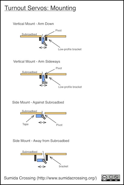
Normally the servo will be mounted flat to the underside of the layout (i.e., with one side of the servo touching the underside) with the horn moving from side to side under the turnout, and a stiff wire going lengthwise along the horn and through a pivot of some sort above the servo. The wire could also go straight up and simply rotate about the spline’s center. However, servos can also be mounted with the spline pointed up (or down) and offset from the point where the wire goes up. Then the wire is at right angles to the horn; in this form a pivot point is always required (the pivot could simply be a small hole below the turnout).
A typical method of attaching these to the underside of a layout is simply double-sided tape. Although they have holes for mounting screws, the normal mounting is not the sideways mounting you’d use on the underside of a layout, so some kind of bracket would be required to use the screw mounts. You can tape a servo directly to plywood, but it’s apparently better to first coat the wood with a thin layer of epoxy and let it dry to create a smoother surface for mounting tape to grip. For an article on creating wooden mounting plates for taping servos to non-plywood surfaces, (in airplanes, but it applies to railroad use also), see this site.
Some sites sell specialized “servo tape”, but all you really need is a good, ordinary, double-sided tape compatible with plastic (the servo) and wood (the layout subroadbed, normally plywood). The Parma brand seems to be well-liked, as is 3M automotive double-sided tape (which probably means 4229P acrylic foam tape) or 4011 outdoor mounting tape. Industrial velcro has also been suggested by some, although I’d think it would tend to let the servo shift position somewhat.
In addition to double-sided tape, some RC hobbyists use “Shoe Goo” to attach servos. This is a flexible adhesive sold for repairing running shoes, among other things. It tends to be too strong though (preventing future removal), so some recommend using a few drops on the corners in addition to double-sided tape for a firm but removable solution.
There are some nice aluminum mounts for small servos available from RC supplier Hobby King (see this blog post for information about them). These are sized for 9g servos. And for some reason they are filed under “Boats” rather than “Servos”, probably because metal mounts are too heavy for airplane use. These don’t have any provision for mounting a micro switch.
The Berrett Hill Shop website lists mounts for both under-table (low-profile and regular) and in-surface mounting of smaller 9g servos. The newest under-table version includes a microswitch for frog power reversal.
Tam Valley Depot makes a laser-cut plywood mounting bracket in kit form for the SG90 (and similar 9g micro servos). It is sold with and without 0.032” wire for the actuator.
If you are into 3D printing, there is a design for a bracket available, this is sized for a 9g “mini” servo (although 9g servos are properly referred to as “micro” so I’m not certain what it’s for). Some people have also made wooden mounting brackets that can be glued to the layout.
One of the more clever solutions I’ve seen (see the video on Loolee.com’s website) is to cut a short length of U-channel about the same width as the servo and slightly longer, drill holes for two mounting screws plus a pivot point hole for the actuator wire to the turnout, and screw it to the underside of the layout, then insert the servo into it (friction-fit). This takes up minimal space, which can be important with a crowded yard lead. If the servo doesn’t fit snugly, remove it, squeeze the channel slightly with a pair of pliers, and try again. Very clever!
It is also possible to mount the servo inside a subroadbed made from 2” insulation foam simply by cutting a slot and gluing the servo in using silicone caulk. This may be a good solution for smaller portable layouts (or if you like using foam as the subroadbed).
Commercial Controllers
There are several commercial products for model railroad use of servos (and there may be others than what I’ve listed below, which are what I found in an evening of online searching). Note that in general, all of these require a separate 5V power supply, although a few of the DCC models take power directly from the track. Also, not all allow for customizing the throw length of the servo, so you should read their materials carefully to determine if they meet your needs.
ANE (and many resellers) sells the Smart Switch in a variety of configurations with and without DCC support. A basic system lists for $87 with four servos or $120 with the add on frog power switch (those appear to be US$ but ANE is a Taiwanese store with prices in dollars, which could mean New Taiwan dollars rather than US or some other currency). The basic set comes with four servos (and mounting brackets!) and there are add-on boards for frog polarity switching and DCC. These are also available from U.S. online suppliers at slightly lower prices.
Berrett Hill sells the Servo Control Base (US$37, but the first requires a setup remote at an additional US$13). This can control up to 8 servos using a simple touch-sensor button.
ESU makes the Switch Pilot Servo v2.0 controller (US$30). This controls up to four servos using DCC or wired switches. It does not directly provide for frog polarity reversal, but the add-on Switch Pilot Extension (US$30) will add this (the combination is a bit on the expensive side). This is available from a number on online retailers. This can be used with their own or some third-party servos. They note some advantages when used with their own servos, but these appear to be based on the servos internal control board and not the Switch Pilot (see the description of their two servos in the list below).
Iowa Scaled Engineering sells three versions of their MRServo switch machine (a control board and servo combination). Ranging from the US$12 MRServo-1, which lacks a frog reversing switch, to the US$18 MRServo-2 that has two accessory contacts, to the US$20 MRServo-3, which has both an accessory contact and a special “PowerFrog” switch that will work with older switches with powered frogs that can be problematic when used with DCC (e.g., the pre-DCC Walthers Shinohara ones). It appears that these do not allow calibration of servo positioning (which means that it assumes a particular mounting type and turnout throw), although they say on their product page that they can make custom versions of the software for positioning if needed. A blog post suggests that the reason for the fixed-throw approach is that this is more reliable over time than calibrated positioning.
Loolee.com sells the MegaPoints controller (50 Pounds, UK), which can drive up to 12 servos (they also have an add-on board to add DCC support) for use with either turnouts or semaphore signals (or other uses). For a large yard or staging tracks, this is probably one of the most cost-effective solutions. It does not, however, include a switch for reversing frog power, so a microswitch would need to be attached somehow or an external circuit used.
Tam Valley Depot sells the Switch Wright, a DCC controller & servo packaged together (US$36). Not cheap, but it allows for switch-based control (with indicator LEDs) in addition to DCC. Includes built-in frog polarity reversing switch. (They also sell the standalone Frog Juicer). For two-switch arrangements (turnouts and sidings) a second servo can be slaved to the first, significantly reducing the cost. They also sell a US$15 basic board without DCC or servo, if you just want button control.
Team Digital sells several different servo control boards:
- Servette (US$30). This drives a single servo using DCC. It includes a DPDT relay for switching frog power (and the second switch can control something else, like a signal). It also supports a wired switch for control.
- SC8 (US$55). This can drive up to 8 servos using DCC (and it also supports Digitrax Loconet). The product page notes that some DCC systems do not support all of the necessary functions.
- SMC4 (US$50). This can drive up to four servos using DCC (it can also drive up to four stall motors in place of, or in addition to, the servos). It does not include a switch for reversing frog polarity.
Arduino Control
When using servos with an Arduino, power is very important to get right. Not only can getting it wrong potentially damage the Arduino, it’s likely to not work reliably if you aren’t careful.
Most of the power used by a servo goes to the motor, so as long as the +5V is connected directly to the power supply, rather than going through the Arduino, the current draw on the control line should be relatively small. So you can drive one of these directly off an Arduino using its “Servo” library and potentially share the same external regulated 5V supply.
There is a program (sketch in Arduino terms) available that uses an Arduino to directly control turnout servos using the built-in library (see this blog post for the source), although it appears from later postings that the author changed his approach to use a driver card along with the Arduino. He’s not the only person who’s done it, either, as can be seen here.
Power Supply
Even small micro servos use a considerable amount of power, often with peak currents close to 1 Amp (1,000 mA). You really shouldn’t power one directly from a microprocessor such as an Arduino, as the typical voltage regulator for one of those will be damaged by currents exceeding 800 mA, and the spiky nature of servo power use may be enough to cause an Arduino to reboot.
Servos are electrically “noisy”, drawing power in sudden spikes. While it is possible to share a power supply between an Arduino (or other microprocessor) and servos with some careful addition of protective circuitry, it’s not really ideal. The best solution is to use separate power supplies. This will avoid risk of the Arduino rebooting due to a brown out.
When wiring an external supply to the Arduino, you can connect an unregulated supply greater than 7V (up to 12V max, some models allow more) to the VIN pin, which may be labeled 9V; power connected to a power jack, if any, goes to this input. Or you could use a regulated +5V supply connected to the VCC pin (sometimes labeled 5V). On the Pro Mini, the RAW pin is used to connect a non-regulated supply, but the FTDI connector’s VCC pin may not be protected against power supplied via RAW. This could make re-programming an installed Pro Mini tricky, and I’ll need to look into that further before using them for real.
Caution: NEVER connect both USB and an external VCC (or RAW) power supply to the Arduino at the same time. You will likely damage the Arduino’s regulator, the computer’s USB interface, or both. The Arduino should allow you to connect both USB and a VIN/power-jack source (if the board manufacturer did their job properly), but connecting USB and a VCC (or RAW) source basically shorts the two together. Use one source at a time for the Arduino; it’s a good habit.
Also: The official Arduino statement on wiring regulated power to the VCC pin is that this is “Not recommended”, although people have done it. Electrically this should be safe, provided that you use a regulated power supply and don’t simultaneously connect a second power source. They mostly seem to be providing the warning for hobbyists who may not exercise sufficient caution to get the voltage right and to not mix simultaneous supplies. But proceed at your own risk.
Connecting a higher-voltage unregulated supply to the Arduino (via VIN) than you use for the servos shouldn’t cause a problem, as it will be regulated down to +5V before being sent over the control line to the servo.
The Arduino supply needs to be sized for the Arduino and any connected electronics (a minimum of 200 mA is probably a good idea). The servo power supply should be sized for the servos. One rule of thumb is to dedicate a 1,000 mA power supply per servo. That’s not a bad solution, although with some minor extra work you can probably drive two or more micro-size servos off a single 1,000 mA supply. While smaller supplies will work, mostly, you may have erratic servo response as a result. So, at a minimum, use 1,000 mA supplies and if you don’t do anything extra, use one per servo.
But if you want to reduce the number of supplies, and are willing to do a bit of extra work, a couple of additional components are also recommended, although not strictly required, as shown in the following diagram.
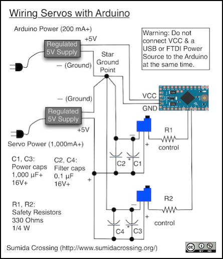
The resistors in the control line are safety resistors. Putting these in isn’t required, but they can prevent damage to the Arduino when something goes wrong, so they’re cheap insurance and always recommended. They prevent excessive currents from the Arduino in the event that the servo power is off or an internal short to ground occurs in the servo control board (inside the servo case). These resistors should be located close to the Arduino. This can also help suppress some electronic noise in the control line from the servo. The exact size of this resistor can vary, see the Safety Resistor section below.
The two capacitors on each servo are a tiny filter capacitor (a small disk-style one, called a “decoupling” capacitor, see this page for info on decoupling) and a large electrolytic capacitor used as a power reserve. These should be connected to each other and to the power wires as close to the servo as is practical. The decoupling capacitor helps suppress electromagnetic noise from the servo, which could otherwise affect other electronics, and the power reserve helps ensure that the power draw by the servo is averaged out over time, which should allow two micro servos connected to a 1,000 mA supply to work reliably.
When connecting grounds together, it’s recommended to use a single common ground point located close to the supply (which means both/all supplies need to be near each other) and run ground wires individually from each grounded device (Arduino, servos) back to that point. This helps to reduce noise induced in the system via the ground. This is easy to do if you use standard servo cables (with three wires) from the Arduino and power supplies to the servo.
If you have more servos, you can either use a larger servo power supply, or connect up an additional one (again with the ground tied to the common ground point).
Safety Resistor
Some servos can produce a lot of noise on the control line. The Arduino should be relatively well isolated from that by its own circuitry, but placing the safety resistor inline in the control line can help. This is also useful if the control line is relatively long, as it can pick up noise from other circuitry (particularly if it’s near track or a power bus carrying DCC) that could interfere with servo operation.
The other reason to place a resistor in the control line is, as mentioned above, safety: if something happens and the servo shorts to ground, a resistor can limit current to avoid damaging the control board. This also applies when powering the servo separately from the control board: if the two have different voltage levels (and they are unlikely to be exactly identical), the resistor will limit current caused by the imbalance.
For resistor size, 150 ohms or more will limit current to 40 mA in a short. A value of 330 Ohms is often recommended, which is even better as it limits current to about 15 mA in a short. If noise is a particular problem, a larger resistor may help (1 kOhm has been recommended by some and 10 kOhms by others), but too much resistance could affect the signal and cause problems.
Another option for limiting control line noise is to place a small capacitor between the control line and ground. This needs to be close to the servo (some servos have these, inside the case) and relatively small. A typical value is 100 pF. This isn’t shown in the diagram above, because it is only needed in exceptional situations, such as when using very long control lines. This won’t protect against a short, or deal with voltage imbalance, so I’d start with the resistor and only add the capacitor if there appeared to be a noise problem (likely appearing as erratic servo operation, although that could also be a symptom of inadequate power or a controller problem).
Servo Control Line Length and Noise
If at all possible, keep the control line from the Arduino to the servo as short as possible. This line is carrying pulses that are unbalanced and can create a fair bit of radio noise (electromagnetic interference, to be technical). This can not only affect radios, and radio controls, but also be picket up by other circuitry and affect it. If the line must be long, keep the three wires of the servo control and power together and apply a twist to them (a few turns per foot).
It may also be useful to add a noise-suppression capacitor at the servo end of the line, between the control line and ground (this is separate from any power line capacitors). This will filter out noise the long wire picks up from other things. A typical size for this is a 100 pF. However, this will only help with high-frequency noise, and not noise at a frequency similar to what the servo uses.
Finally, keep the servo lines well away from both track and any power bus carrying DCC signals. These use similar frequencies to the 20 kHz used by servo control lines (DCC is variable but around 5 - 8 kHz), which make them particularly prone to interfere with each other (twisting both the servo wires and the track bus — separately, not together — helps avoid this, but you can’t twist the track itself, so keep the servo wires away from it).
Sizing the Power Supply
So, if you use a separate power supply for the servo, or servos, how big should it be? That depends on the servo. Some micro servos are very efficient, using only 400 mA at stall. Many of the cheaper ones, however, particularly those with larger torque ratings, are closer to 1 Amp (1,000 mA). As noted above, if you use power capacitors, you should be able to fit at least twice as many servos on a supply than if you simply wire the servos directly to it.
Servos will use less power when they aren’t stalled (and normally draw stall current only very briefly). At rest without a load, they draw next to nothing. In motion at reasonable speeds usage is probably a few hundred mA. I measured 200 - 400 mA throwing an unloaded SG92R at a slow speed, but this went up to over 600 mA at full speed, and stalled against a load it peaked at 900 mA.
You could simply use one power supply per servo, and wire all their grounds together and to the control board (as shown above). An alternative solution is to use a larger multi-amp power supply, although this can quickly become expensive. Note, however, that stall current is peak current, and servos use power in a very “spiky” manner, typically running the motor for less than 2 milliseconds out of every 20 milliseconds. If you attach a large enough capacitor across the servos + and ground wires, this will average out the power load to something closer to the rated “typical” current.
Some people recommend putting a large capacitor at the power supply rather than individual ones at the servos. This would have to be very large to be useful, and really large capacitors can be dangerous. I wouldn’t recommend that approach.
If you know your servo’s characteristics, and use some capacitors, you may be able to fit even more than two micro servos on one shared 1,000 mA power supply and still have them operate reliably as long as only a couple throw at the same time. A more cautious approach would be to limit yourself to two per supply (with capacitors) or even one (without capacitors). As suitable power supplies cost only a few dollars this is something of an optimization, but if you’re building a yard ladder with twenty turnouts the cost savings can add up quickly.
Sizing the Power Capacitor
What is a good size for the capacitor providing a power reserve? Various online sources recommend sizes of 470μF, 1000μF, 2200μF or more. One way to size this is to ensure it can provide the necessary power for one cycle of the servo’s power draw with a specified limit on voltage drop. The important formula for this is C = I x T / V, where I is current in Amps, T is time in seconds, V is volts, and C is capacitance in Farads.
An analog servo uses pulses of up to 2 milliseconds duration (every 20 milliseconds). If we assume a reasonable voltage drop is 0.5V, and that the servo will be drawing a stall current of 900 mA, then the calculation is C = (0.9 x 0.002)/0.5 = 0.0036, or 3,600μF. That’s fairly large, but not unreasonable. If you assume your normal maximum is 400 mA, then under the same constraints, this drops to 1,600 μF, so a 2,200 μF capacitor will be enough for most situations. I’d be reluctant to go lower unless I was using very power-efficient servos.
It is important to provide a good safety margin on capacitor voltage ratings, and because servo voltage may include noise spikes considerably larger than the standard voltage, use more than the usual 2x safety margin. A 25 or even 35V capacitor is not a bad idea, and they aren’t much larger or more expensive. Remember that over-voltage capacitors have a nasty habit of exploding, so be extra cautious.
If you add a noise-limiting (“decoupling”) capacitor to the power lines, as close to the servo as possible, this will help limit the high-frequency peak voltage that the larger capacitor has to deal with. As shown above, a typical size for this is 0.1μF.
Inrush Current
With large capacitors you may need to be concerned about inrush current as well, particularly if you have lots of servos linked to one supply. Inrush current is what happens when you first turn the power supply on, and it tries to charge up all the capacitors simultaneously. This is a bigger problem with large capacitors, and will overload the power supply to an even greater extent than the servos would have, if not controlled, possibly enough to trip its circuit protection. The problem is that methods to limit this will also affect the ability of the capacitor to recharge and can limit power to the servo, causing erratic behavior. This is an argument in favor of smaller capacitors, and fewer servos per power supply (more small power supplies means fewer servos on each, and thus fewer capacitors to recharge on each, and less overall current).
If you are only connecting two servos to one 1,000 mA supply, you should be able to ignore this. If you use a larger supply, or lots of servos, this is more likely to become an issue. At present, I don’t have a solution for this. Adding resistors (the usual simple choice) doesn’t look like it will work, as ones large enough to be useful limit the recharge time unacceptably (and need to be fairly high wattage, which wastes power in another way).
Stall Current
Numbers for servo stall currents aren’t normally published as part of the specs, probably because you aren’t supposed to actually make them stall. But stall current is a measure of maximum current draw by a DC motor, used when starting up or when stalled against and obstruction, so it is an important number to know when sizing power supplies and related components. And servo stall currents are surprisingly high.
I measured a number of typical micro-size servos from several different manufacturers. All were 9g micro size, and all but one were analog models. The only one that wasn’t over 750 mA was the HiTec HS-55, which had the lowest torque (1.2 kg-cm) of the group, and a stall current of 340 mA. The others ranged from 760 to 900 mA, with one drawing 1,300 mA. Oddly my one digital servo had a peak current in the middle of the range: 900 mA. I was expecting it to be higher. Its average current likely is higher than the others, but I didn’t measure for that.
Now these weren’t precision measurements. I used a cheap uncalibrated servo test meter (a Hobby King 20A Watt Meter and Power Analyzer). The current accuracy is rated as +/- 10 mA, however since my meter noted the supposedly 440 mA HS-55 as 340 mA, it may have been reading low. It is pretty clear that most of these small servos draw some pretty serious current. The rather hefty force they can apply comes at a cost.
As discussed above, that’s going to be peak current, and the average will be lower. It’s also worth noting that stall current is likely drawn only very briefly when starting the motor from a stopped position, unless you jam it against something. But it’s important to understand the peak, since that’s what you have to size supplies for if you want reliable operation.
It’s also clear that powering most of these off an Arduino is simply asking for trouble. I used a benchtop 5V supply that’s rated to deliver 3A for my tests to power my test servos separately from the USB-powered Arduino (with grounds connected as shown in the wiring diagram above).
Servos for Model Railroad Use
There are a number of manufacturers of servos, and a dizzying array of models. The following is a small subset of the ones that appear to be both low-cost and appropriate for small-scale model railroad use. As yet, I have done only minimal testing of these, and am mostly reporting catalog information and other things I’ve read. One of the leading vendors is HiTec, but they’re also a brand and tend to cost more as a result (you may also get better reliability). Servos are typically sold by shops specializing in RC (radio-control) or robotics hobby supplies rather than being available from the manufacturer. Some model railroad stores are starting to stock the more common ones.
As with most electronics, buying online (from E-bay or other outlets) and in bulk may provide significant savings, assuming you use a trustworthy supplier. There are a lot of counterfeit items out there, poorly made clones of branded items, or just poorly-made no-brand items. But there are also well-made yet inexpensive servos from brands you many never have heard of. Quality can vary considerably, so doing business with a known seller who provides a warranty is probably a good idea, to ensure a minimum level of quality. Even well-made cheap servos may not last as long as more expensive ones, but in volume at those costs, they’re probably going to be less expensive even if you have to replace a few over the years.
All of the hobby servos I’ve encountered require +5V power (or more correctly, a range that includes +5V but not +12V), so these cannot be connected to layout “accessory” power sources, which are typically 12 - 16 V.
Many of the sellers of control boards either sell servos separately or package servos with their product. These appear to all be 9g “micro” size servos, but few provide even that much information about them and they are probably less-expensive Chinese-made non-brand models (which isn’t necessarily bad, if the reseller is providing a warranty).
Note: The “micro” size servos come in slightly different sizes from one manufacturer to another. Their dimensions aren’t always given the same way, and may even differ from site to site. For example, the HS-55 is slightly smaller in width and thickness than the SG92R, but the SG92R and Turnigy 50090M I have are the same size, despite having slightly different dimensions on paper.
Prices are U.S. “street price” (or price on U.S. oriented Asian websites) as of early 2015 unless otherwise noted.
ESU 51804, US$15
This is a kit with a servo, mounting bracket, horns and an actuator wire, so the price is on a par with some others, although significantly more than the lower-priced ones. The linked description notes other features of potential benefit for model railroad use other than throwing turnouts (such as door opening and crossing gate operation): higher precision and suppression of start-up motion. The servo may be made by Graupner, but does not appear to match any of their standard models. Gears: plastic. Size Micro (9 gram), 26 mm x 13 mm x 24 mm. Throw: unknown. Speed: 0.36s/180°. Stall torque: “up to 1.0 kg-cm”.
ESU 51805, US$19
Similar to ESU 51804 except for the gearing, this is a kit with a servo, mounting bracket, horns and an actuator wire. The same benefits are listed as for the 51804.The description seems to imply that the servo is both noisier and more powerful than the 51804, but the same torque is listed. Gears: Metal. Size Micro (9 gram), 26 mm x 13 mm x 24 mm. Throw: unknown. Speed: 0.36s/180°. Stall torque: “up to 1.0 kg-cm”.
Hextronic HXT 900, US$4
This is a well-known micro servo, very similar to the Tower SG90 (and reportedly made by the same company). Gears: “plastic” (likely nylon). Size Micro (9 gram), 22 mm x 12 mm x 22 mm. Throw: 180°. Speed: 0.36s/180°. Stall torque: 1.6 kg-cm (22 oz-in). Motor is reportedly a “coreless” design. I’ve seen reports that these have a 750 mA stall current, but don’t have one to test. There are a number of reports online of problems suggesting poor quality control (google for them), so be sure to buy from a supplier who provides a warranty.
HiTec HS-55, US$10
This is HiTec’s 9g servo (it actually weighs 8 grams). Gears: nylon. Size Micro (9 gram), 22.8 mm x 11.6 mm x 24 mm. Throw: 90° with standard pulse, 180° possible with special controller. Speed: 0.54s/180°. Dead band: 8 μs. Stall torque: 1.2 kg-cm (17 oz-in). Motor: I have seen this described as “coreless”, but the box mine came in says “3-pole Ferrite motor” . Stall current is reportedly 440 mA. Measured Stall Current: 340 mA.
HiTec HS-311, US$8
This model was reviewed on Model Railroader’s website in 2014. It is, however, larger and more powerful than most servos typically used for model railroad turnout applications. Gears: Resin. Size: Standard (43 gram), 19.8 mm x 39.9 mm x 36 mm. Speed: 0.6s. Stall torque: 3.0 kg-cm (42 oz-in). Motor: 3-pole. Current: 7.4mA idle, 160 mA operating. Stall current is reportedly 800 mA.
Tower SG90, US$4.75, US$4 in bulk
This is the original Tower 9g servo, used in a number of older Model Railroad applications and still listed on the Tam Valley website as of early 2015. It has apparently been replaced by the SG92R on most sites. Gears: “plastic” (likely nylon). Size Micro (9 gram), 23 mm x 12 mm x 29 mm. Throw: 180°. Speed: 0.3s/180°. Stall torque: 1.8 kg-cm (25 oz-in). (also seen as 1.2 kg-cm, 17.5 oz-in at 4.8V). Dead band: 10 μs. Note: the SG91R appears to have the same specifications.
Tower SG92R, US$6
This is an upgraded and supposedly slightly stronger version of the older SG90. Gears: Carbon. Size: Micro (9 gram), 22.2 mm x 11.8 mm x 31 mm. Throw: 180°. Speed: 0.3s/180°. Stall torque: 1.6 kg-cm, 22 oz-in (I’ve seen this rated as 2.2 kg-cm, 30.5 oz-in also). Measured Stall Current: 900 mA. Measured typical current 200 mA to 400 mA in motion with minimal load (speed dependent).
Turnigy TSS-9, US$4
This is a digital servo I bought to evaluate differences from analog ones. Gears: appear nylon, but are listed as “a combination of metal, carbon and plastic”. Size: Micro (9 gram), 23.1 mm x 12 mm x 24.9 mm. Throw: 180°. Speed: 0.33s/180°. Stall torque: 1.9 kg-cm, 27 oz-in. Measured Stall Current: 900 mA.
Turnigy 50090M, US$5
Relatively inexpensive for a metal-geared servo, and with otherwise good specs at a very low price this may be the best I’ve found so far. However, online experience seems very limited so far. Gears: “all metal”. Size: Micro (9 gram), 23.1 mm x 12 mm x 25.9 mm. Throw: 180°. Speed: 0.24s/180°. Stall torque: 1.6 kg-cm, 22 oz-in. Measured Stall Current: 760 mA
Turnigy TG9e, US$2.34
This is a small, cheap servo. The description notes that it isn’t as resistant to “crashes or overloading” as the HXT900, nor does it have the “strength or longevity”, but is otherwise similar. It’s probably not a good choice: although inexpensive, you’ll spend part of the savings on a larger power supply. Gears: plastic (nylon). Size: Micro (9 gram), 23 mm x 12.2 mm x 29 mm. Throw: 180°. Speed: 0.3s/180°. Dead band: 7 μs. Stall torque: 1.5 kg-cm, 21 oz-in. Measured Stall Current: 1,300 mA.
Note: Uhlenbrock servos don’t appear to be available in the U.S., but they are in other English-speaking countries, so they’re worth mentioning.
Uhlenbrock 81410, UK 10 Pounds, AU$19
This is a very small servo, more suited to scenic use than for turnouts. It is sold as a set with two actuator wires and some kind of “mounting materials”. Size: subMicro, 20.0 mm x 8.0 mm x 17.6 mm. Throw: 90°. Speed: unknown. Stall torque: 4 Ncm (0.4 kg-cm, 0.6 oz-in).
Uhlenbrock 81420, UK 10 Pounds, AU$19
This is sold as a set with two actuator wires and some kind of “mounting materials”. Size: Micro, 22.2 mm x 11.1 mm x 20.0 mm. Throw: 90°. Speed: unknown. Stall torque: 13 Ncm (1.3 kg-cm, 18 oz-in).
