


DCC Power Supply
The Digitrax command station I settled on using, the DCS 100, provides up to 5 Amps of track power. With six tracks (not counting the helix or storage tracks), and the likelihood of having at least two trains on each of the commuter tracks (three if I want to get clever), it’s possible that even a 5 Amp command station could be inadequate. However, the more I look at it, the more it seems that a typical train is going to use less than 200 mA (0.2 Amps), for one 5 Amp supply should cover my needs. But just in case, even though I’m starting with just the command station, I’m planning for subdividing things and adding booster later if I want.
My command station, and any future booster stations, need a 5 Amp 12 Volt DC power supply. Digitrax makes the PS2012 supply, which can drive up to four such stations. A “scale” switch on it controls the output voltage: set for N-scale, it outputs 13.8 volts DC (which is “close enough” to 12 volts, per Digitrax’s manuals) at up to 20 Amps total. A special cable, part YC52, splits one of the supply’s two outputs into two, with inline 5 Amp circuit breakers. Without these, some separate fusing would be required to protect the command station input line. With a pair of these cables, and the supply set for N-scale, I have four 5-Amp, 13.8 volt DC power supplies. I only need two, so the other two will be used for DCC accessories.
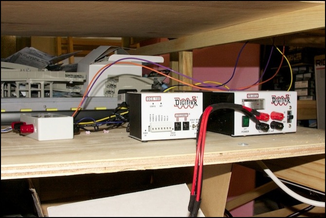
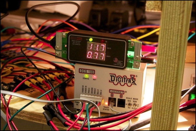
The PS2012 (right) and DCS100 (center), along with the fuse box for the Lighting power supplies.
But that’s not the whole story. It’s actually good that the PS2012 puts out 13.8 Volts, because some of that voltage will be lost in the conversion to DCC, and I may want a bit more than 12 volts at the booster output. The DCS 100 has a nominal output of 12 volts DCC RMS on the N-scale setting, but it’s not exact, and a calibration set-screw is provided to adjust it. That’s really not necessary unless you’re operating with boosters, in which case the track voltages from each should be identical to that from the command station. But I never saw a changeable setting I didn’t want to make “right”.
So, apart came the DCS (in accordance with Digitrax’s instructions for adjusting the voltage; disconnect power before opening the case or making adjustments). I took some photos, and you can see them on my Electronics photo album.
Digitrax recommends measuring the Rail A and Rail B outputs relative to the ground line with a DC meter, and adding the two. This provides a “peak DC” voltage. I used this method, in addition to a “true RMS” meter measuring Rail A to Rail B and an RRampMeter (also RailA to RailB). It’s a truism that a man with a watch always knows the time, and a man with two watches never knows the time. This applies to meters too.
Out of the box, the DCS 100 measured 11.4 Volts on the DCC RRampMeter, 11.03 volts on the AC scale of my “true RMS” meter (so despite being a very good Fluke meter, it doesn’t much like square waves, or else it’s right and the RRampMeter isn’t calibrated properly), and 11.8 volts peak via the DC meter. A DCC RMS measure of 11.4 is consistent with a peak reading of 11.8 (RMS should be identical to peak with a square wave, but below it for a real-world approximation to a square wave), so I’m inclined to trust the RRampMeter. Turning the set-screw a bit less than a quarter turn clockwise gave me 12.0 DCC RMS (RRampMeter), 11.58 AC RMS (multimeter), and 12.23 peak (multimeter on DC scale). I don’t know if it’s right, but it’s darn sure close to it.
My theory was that one of the benefits of having it at exactly 12.0 on the RRampMeter would be that when I got around to checking voltage levels on the track with the meter, it would be easier to figure out the exact voltage drop at any point (I’m bad at math, even subtraction). Alas, real life isn’t that clean.
Actual Output and Track Voltage
The above 12.0 DCC RMS voltage is what the command station puts out when it has no load on it, after a bit of fine-tuning with the adjustment. That “no load” voltage isn’t really representative of what will happen when a train draws power. But real trains aren’t a constant load. They also move, which makes it hard to pin down a bad spot. The solution is to connect a 12 volt light bulb to the meter. One rated for about 18 watts will produce a real-world steady-state 0.8 Amp current (why this isn’t 1.5 Amps is a mystery to me; I suspect it has to do with the difference between a cold bulb, which draws maximum current, and a warm bulb, which reaches a lower steady-state current, but it may be related to the AC nature of the DCC waveform). Larger bulbs, like the commonly-used 1156, may draw too much current when cold and cause a circuit breaker to trip.
Using a load is important, because voltage loss varies by current. A 0.8 Amp current approximates the likely worst case (a sound-equipped passenger train with lots of bulb lights). Thus, with such a load connected to my meter, I should see a good representation of the worst voltage trains will actually experience on the rails.
Exactly what voltage should be on the rails is something of a mystery, as I noted above, but it’s clear that for N-scale it shouldn’t exceed 12.0 volts DCC RMS by a large margin, and as long as its above 10 volts and below 14 volts it should be acceptable.
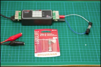
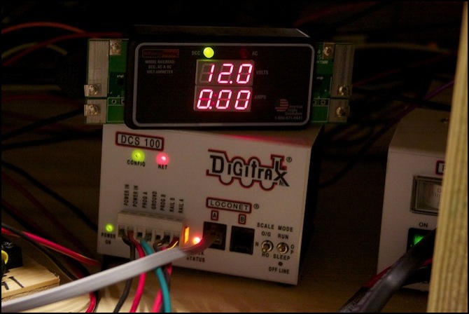
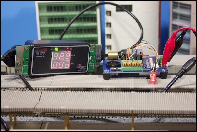
RRampMeter with 18W bulb as load
I used an automotive 211-2 lamp, which has convenient metal loops on the end to solder to, and attached a couple of short wires to a pair of banana plugs I could connect to the “track” side of the RRampMeter. Then I connected the probe wires to the “booster” side of the meter (you can also just touch the meter to the track, if your track is easy to reach, but much of mine is underneath other things, so I’m mostly using the probes). One caution: that bulb gets hot, fast. It’s important to keep it away from plastic buildings (and my arm).
With that, output at the DCS 100 can be seen to be 11.4 Volts under load, rather than 12.0. And moving around the layout I saw voltages varying from very close to that (adjacent to some, but not all, feeder connections) to as low as 10.0 volts. My first thought was to boost the DCS 100 output to make the load voltage closer to 12.0. As it turns out, I was nearly maxed out on the adjustment screw.
The maximum I could get was 12.3 V DCC RMS unloaded (11.88 AC RMS on the meter, 12.56 DC peak), or a loaded voltage of 11.7 V DCC RMS (11.40 AC RMS, 12.77 DC peak). So I’ll have to be content with that, and turn my attention to minimizing loss.
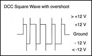
Note: under load, the DC peak measurement method becomes a lot less accurate. I suspect this is because of distortion of the square wave when the power supply amplifier has to work harder (i.e., brief spikes at the leading edge of each wave as the voltage overshoots). While this shouldn’t pose a problem for equipment, since the amount of actual power contained in a brief spike is low, it does mean that the peak method is really only useful for establishing the baseline “unloaded” value, and a real DCC meter is needed for checking power under load.
Oddly, the “true RMS” meter was more accurate under load (probably because the distorted wave was closer to a sine wave, or perhaps it’s just a coincidence).
Voltage under load
While my bus wiring could have been part of the problem (there are a lot of terminal strips and crimp-on connectors), the drop even at the far end of the bus is only 0.2 volts. And the way that voltage falls off by up to two volts as I move away from the feeders tell me that the principle cause of loss is poor Unijoiner connections. The solution, if one is needed, is adding more feeders. I already have them every four feet or so, as that’s my typical block length, but I can have multiple feeders per block if I need to. This isn’t entirely unexpected: one of the most common bits of advice for using DCC with sectional track on a semi-permanent layout (aside from “don’t do that”) is to attach a feeder to every piece of track. Which would be a lot of work.
Another thing you can do (and I’d done this already) is to check the quality of your Unijoiner connections by measuring resistance across them. Simply set a multimeter to the resistance scale (if you have a 1-100 Ohm scale, use it) and touch the contacts to the rail on either side of the unijoiner. I typically touch the probes to the rail in the middle of each unitrack section to avoid bending the track at the unijoiner as the loss in a few inches of rail is negligible.
Doing this, I’ve seen resistance around 1 - 3 Ohms for the most part, with 5 - 7 Ohms in a few places that seem to correspond to my lower voltages. But replacing the Unijoiner didn’t lower the resistance significantly, so I suspect variations in the track that cause it to make poor connections with the Unijoiner are at fault. In a few places I saw resistance of 15 or even 30 Ohms which was traceable to the unijoiner. But I had removed and discarded those Unijoiners long before I got to measuring current and voltage, so I don’t know what kind of loss they’d have caused (nothing good, I imagine). My rule of thumb: if resistance across a Unijoiner exceeds 5 volts (or 3 if I’m seeing any kind of problem) replace the Unijoiner with a new one (they’re cheap!) and immediately throw the old one in the trash so you don’t re-use it accidentally.
Of course you can also solder track together, or solder feeders to every Unijoiner, and some purists do this. If I were going to do that much work, I’d simply use flex track (and maybe someday I will). For now at least I just want to make my Unitrack work as well as sectional track can work while still being removable, because the layout is designed to come apart when moving.
I still have a bit more work to do, getting the DCC command station adjusted to what I think is good, and wiring up the existing feeders with circuit breakers and occupancy detectors. But at this point, the Express line is fully operational for both DC and DCC and seems to work just fine. Then I just need to convert my trains to DCC, which is going to be a big project.
How clean is DCC?
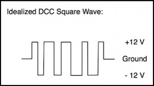
The above raised the question: just how clean is my DCC? Well, there’s an easy way to check this: use an oscilloscope. Okay, not everybody has one of those (although they’re fairly inexpensive now), but I just had to know what was really going on. As you can see from the photo below, the output of my Zephyr with no load and a very short piece of track connected is really close to a perfect square wave. Any overshoot is at most about 0.5 volts, and probably around half that since it doesn’t appear on every wave.
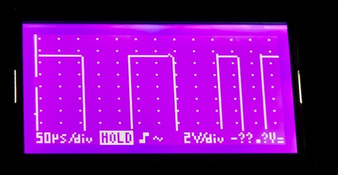
Clean DCC (output of Zephyr with no load and short track, waveform magnified)
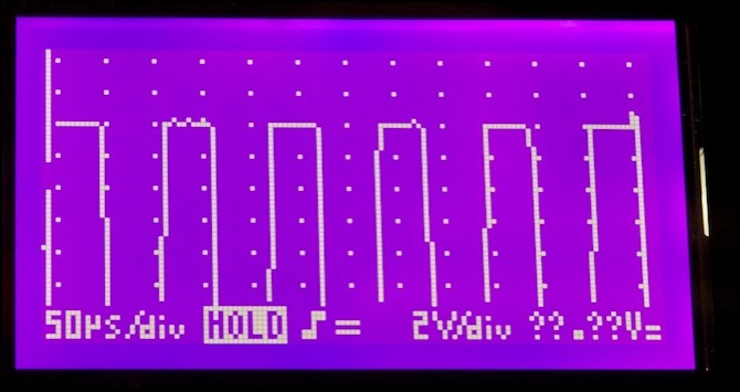
Now when you hook things up to a more complicated track, things aren’t quite as clean, but they’re close. The photo below shows the DCC signal on the track under the urban station, with a train running in the same electrical section where the scope was connected. The wave form is a bit rougher, but still essentially square-edged.
Motor Voltage
The real goal, of course, is power to the motor. And the question is: what is the relationship between track DCC voltage and motor DC voltage? To check this out, I used a Digitrax DZ123 decoder (small, but quite functional) in my ESU 51900 Decoder Tester. In addition to checking function outputs, this has a motor, and while it won’t give quite the same results as a moving train (a motor under load draws more current, and will likely cause a reduction in voltage), it should provide a good indication of how much voltage is directed to the motor.
I hooked this up to the track through my RRampMeter, so I could tell the track voltage, and the exact current being drawn. I checked the motor voltage using a handheld DC meter touching the input tabs on the motor with the meter’s probes.
I tested this in a couple of places, connected next to the command station, and to the track at the far end of the bus (subway track under the Urban Station). This is where I saw over a 1 volt loss using the car lamp load, but even with the motor at full throttle, track voltage dropped by only 0.1 volts. Of course, the current it was drawing was barely 30 milliamps, rather than the 770 milliamps the lamp draws.
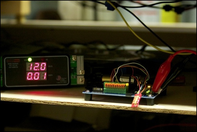
Track voltage 12.3 V DCC, current 0.03 Amps, throttle at full (“99”)
In the end, I went back to working at the command station (there’s a shelf for the equipment there, rather than resting everything on the station platform roofs). What I saw was that motor voltage at maximum was 11.4 volts DC (using my DC meter across the motor poles) when track voltage was 12.3 V DCC. Where the track voltage was 12.2 volts DCC, motor voltage was 11.3 V DC. So there was approximately a 0.9 volt difference. I also noted that with the default programming, the motor was receiving half power (5.8 volts DC) when the throttle was set to just 11 on the 0-99 scale, but it needed to be all the way to 99 to get full voltage. But see further down the page for a comment on the accuracy of measuring motor voltage with a DC meter.
Motor current, by the way, peaked at 0.05 Amps (50 milliamps) at about throttle setting 7, which was a relatively slow speed and fell off to as little as 0.01 Amps at full throttle. Stall current (with the flywheel held with a fingertip) was 0.14 Amps at half-voltage (throttle 11), and 0.64 Amps at throttle 99. However, this may not be the best way to measure stall current, since the decoder needs to be installed first. The method described on my Power Pack Testing page is preferable.
Final Calibration
After all this, I decided to set the DCC track voltage back to 12.0 Volts DCC at the Command Station as that appeared to be putting less strain on the output. This reduced the maximum motor voltage to 11.1 Volts DC (from 11.4). Final numbers:
With throttle on loco 0, track voltage 11.9 V DCC, 11.52 V AC (meter), 12.22 V DC peak.
With throttle on loco 3, 0 speed, track voltage 12.0 V DCC, 11.64 V AC (meter), 12.31 V DC peak.
With throttle on loco 3, 99 speed, track voltage 12.0 V DCC, 11.55 V AC (meter), 12.30 V DC peak, and motor voltage 11.10 V DC.
Note: well after I wrote this, I realized that measuring the motor voltage with a DC meter may be inaccurate, as decoders use Pulse-Width Modulation (PWM), a form of pulsed DC power, to provide variable power to the motor. And a DC meter may not provide a good measure of a PWM signal, particularly at lower “voltage”. At full throttle it might be close, but I don’t know that for certain.
These measurements have convinced me, by the way, that a “true RMS” meter isn’t particularly useful for DCC. It’s certainly possible that it is right, and the RRampMeter is wrong, but the way the error varies suggests that it’s the “true RMS” meter that is wrong.
I’m fairly content that this will provide adequate power to the motor, even with a couple of volts lost to dirty track and unijoiners.
Power Management Panel
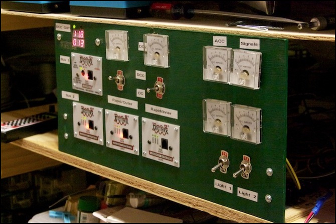
The power management panel provides ammeters to monitor the six DC power supplies (command station, booster, signaling, accessory, lighting 1 and lighting 2) and switches to set the two tracks of the outer loop to DC (from a dedicated Kato power-pack per track) or DCC. It also includes on/off switches for the two lighting supplies (so I can leave those off for “daytime” operation) and LocoNet panels. And finally, there is an RRampMeter connected to the input from the Command Station to monitor voltage and current drawn by DCC trains (on any track not fed from the not-yet-needed booster). See the diagram at the top of this page for an illustration of the various power busses (all route through it).
Each of the four LocoNet panels on the front (three LNRP and one UR92) is connected to one of the four power busses (DCC1, DCC2, DC/DCC3 and DC/DCC4) to monitor track status. There’s a fifth panel, out of sight to one side, which is where the wireless throttles will be left plugged in when not in use. It’s powered by a dedicated PS14 power supply, which remains on when the master power switch is turned off, to keep the batteries in the throttle fully charged.
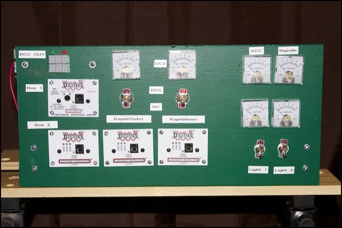
Power Panel - Front View
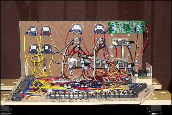
Power Panel - Rear View
Power Panel - Installed
