


Brushed DC Motor Technology and History
Electric motors and model trains go way back: an early motor, one of the first designed to be more than a laboratory curiosity, Davenport’s motor of 1834, was a brushed DC motor (using stator coils, not permanent magnets, so it was what modelers call a “wound field” motor). In 1835 he demonstrated it using a model train on a small circular track. It wasn’t a scale model of anything, nor intended to be used as a layout, but it was a model train driven by a DC motor.
Electric motors didn’t really catch on for industrial use until the 1880s. Early model trains (from the 1840s onward) used either windup “clockwork” drives or were live-steam models, if they moved under their own propulsion (many were simple unpowered toys). The first known use of an electric motor in a model train (aside from Davenport’s) appears to be one produced by the Märklin Bros. & co. (a company formed in 1891 from the merger of two others) in the early 1890s, although the Carlisle & Finch company of Cincinnati, Ohio is sometimes credited as first with an 1897 toy. These early models, along with a very successful one introduced c. 1909 by Lionel, all used AC motors. In fact at least some used wall-outlet voltage on the rails, rather dangerous by modern standards.
But the DC motor didn’t become popular for use in model trains until the 1930’s, when the brushed permanent-magnet DC motor eclipsed the AC motor. Those early motors were very similar to the ones we use today, and yet the technology has also changed significantly. Modern motors pack more power into a smaller space, operate more reliably at low speeds, and are nearly maintenance free. This page will cover the way these motors have developed since they were first introduced, and cover the most important characteristics found in their modern form.
References for this page are listed at the end of the parent DC Model Train Motors page.
Early History and Development
The use of DC motors in scale model trains goes back to the 1920’s at least. DC quickly overtook AC (although AC continued to be used). In the U.S., according to this history, Mantua (later to be known as Tyco) first advertised their six-volt model 100 DC motor in a hobbyist magazine in 1930. While they also made AC motors, by January 1935 Model Railroader (MR) could note that “most” modelers in the then-new HO scale were using DC motors. The majority of these early motors, although not all, were permanent-magnet motors, and initially 6V was the standard voltage.
Other early motors were “universal” motors, which used a wound field that could operate on either AC or DC power. This was attractive at a time when modelers were converting from one system to the other.
In May of 1936 Mantua advertised their first motor purpose-built for HO scale modelers, a 7/8” x 1 1/2” x 2 1/2” (22mm x 37mm x 64mm) 6-volt open-frame DC permanent-magnet design. It sold for $4 and came with a money-back guarantee. It was so unique it didn’t have a model number, it was just described as “the HO motor”. A typical design for this motor (per Building a Locomotive by Frank Taylor in the November 1936 issue of MR) used a 30:1 reduction gearing with 79” (scale) driving wheels to build a USRA Pacific locomotive. Typical top speed for the prototype of these locomotives was 75 mph (in part due to wartime restrictions; the USRA was in use during the First World War), which implies that the motor needed to be able to turn at about 9,600 RPM under load to achieve a prototypical top speed. These two numbers (30:1 gear ratio for a steam locomotive and operating speeds of around 10,000 RPM) continue to be common today.
Note: considering only inflation, US$4 in 1936 would be worth US$67 as of 2014, so this wasn’t a cheap motor, particularly considering that this was the time of the Depression, when many people were underemployed if employed at all. Typical prices for motors used for “repowering” model trains in 2014 are around US$50 to US$60 (although some can be had for half that), so it wasn’t terribly overpriced either.
In 1937 Pittman, a company that would later become synonymous with quality model railroading motors, advertised their HO motor, a 1/2” x 3/4” x 1 5/8” (12mm x 18mm x 41mm) open-frame design, also operated on 6-volt power and selling for just $3. The company also sold a 30:1 gearbox for use with it, so its performance characteristics were likely similar to the Mantua. The basic characteristics of motors were set, and wouldn’t change except in detail down to this day. Other manufacturers (Varney and Knapp among them) were soon producing motors as well. Later, somewhat higher-speed motors would be introduced, although gear ratios seem to have remained much the same. Models of diesel locomotives (and multiple-unit trains) would use lower gear ratios due to their smaller driving wheel diameter.
Note: passenger locomotive models, where high speed was more important than pulling power or smooth low speed operation, typically used 15:1 gear ratios with the same motors. Again, this was for steam engines with large driving wheels, and others would differ.
Use of 12V motors was common even before the Second World War (an August 1934 MR article discussed their use) but this was likely for O scale and not smaller scales. Six volt motors were the HO standard up until the war, when production of motors for hobby use ceased due to restrictions on use of materials like copper. By the end of the war opinions had changed, and 12 volts became the standard for HO. This was likely as the result of standardization efforts by the NMRA, but I haven’t been able to find any history of the early standardization activities to confirm that. I do have confirmation that there were NMRA standards for motor voltage by 1947 (12 volts for O, S, OO and HO), but that’s after the motors were commonplace.
After the war, motor production resumed in the fall of 1945, with Mantua, Pittman and Varney announcing 12-volt HO motors (Mantua’s was actually made by Pittman now) and some stores offering a trade-in credit for people returning a 6-volt motor when buying a 12-volt model. Twelve volts would continue to be the standard track voltage for many years, and was common for HO and even O up to the 1970’s at least. Even today motors in HO are typically tested by reviewers using 12 volt power supplies, and it’s considered “the standard voltage”, even though the typical HO power pack is putting out 16 or more volts and the NMRA doesn’t specify standard DC voltages any more.
In the spring of 1946 Pittman announced their DC 60 and DC 71 models (the hyphen was added to the model numbers later), both twelve-volt, five-pole open-frame Alnico permanent-magnet brushed motor designs with straight windings, intended for HO scale models and with a no-load speed around 12,000 RPM and a recommended maximum speed of around 9,000 RPM. The DC 71 had many descendants and a version was still in production when Bowser bought the open-frame motor designs and tooling from Pittman around 1980 (Pittman still makes can motors, and by report those are used in some O-scale trains). In 2000 Bowser introduced a DC-71 (still using that model number and of similar specifications) that used a skewed winding. That motor in this new form remains in production as of 2014, a very enduring design after 68 years.
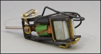
Bowser DC-71 (purchased early 2014)
The same issue of Model Railroader (April 1946) also saw the introduction of the first (as far as I can tell) model train motor with skewed windings (see the section on this below), the Famous Model Company’s FAMOCO Red Devil. This was also a five-pole design, available in 12-volt (for “OO and S gauge”) and 18-volt (for “O gauge”). So apparently the “standard” for O was somewhat flexible even back then.
By 1948 Lindsay was producing a line of “seven slot skewed armature” HO motors for 12-volt use, although these apparently didn’t find a huge market and the motor business was sold in 1950 to a non-modeling company. Bob Lindsay had also been the designer of Varney’s postwar motors, according to his obituary in the December 1968 issue of Model Railroader.
The Can Motor and the New Open-Frame Motor
Open Frame motors are just what they sound like, the frame around the moving parts is not solid. This can allow dust and other debris inside, unlike a “can” motor that has a solid shell. On the other hand, an open-frame motor will run cooler because air circulates around the wires (which heat due to electrical resistance), and inside a closed chassis dust shouldn’t be a big problem. Both types of motor are used in model trains today.
Open frame motors were typical up to the 1960’s, and came in three, five and (in larger scales) seven-pole designs (we’ll get to why that matters in a bit). Can motors were introduced when Japanese manufacturers became involved in the hobby around the 1960’s and started using motors originally designed for use in electronics equipment. Neither is inherently better or worst than the other, although specific examples of either can be good or bad.
Many modern can motors are designs created for use in consumer electronics or automobiles (e.g., external mirror adjustment motors). These often aren’t intended for continuous duty, and can thus be less than ideal in a train that may be pulling a load for hours. While a good manufacturer will take this into account, and select motors either designed for heavier duty, or oversized for model-train loads, this isn’t always the case.
From the 1980’s, repowering of locos originally sold with cheaply-made motors (many of open-frame design; many cheap open-frame designs existed) with imported Japanese can motors of high-quality was a popular activity. This has led to the association of can motors with good designs, although many early ones were of quite poor quality. The reality is that it’s the individual motor, what it was designed to do, and how well it was made that matters, not the form of the container around the motor.
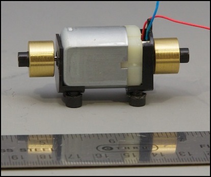
Typical Can Motor (Walthers HO) with flywheels and support frame
But can motors didn’t replace the open-frame design entirely. Although the original one-magnet design is rare now, newer motors with dual magnets but an open frame are also in use. These typically use a plastic frame around a U-shaped metal part that holds two magnets in place on opposite sides of the motor.
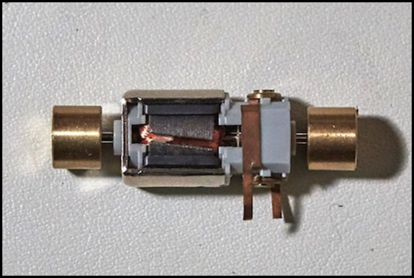
Modern Kato open-frame motor
Note: the large, brass, flywheels seen on both motors technically are not part of the motor but of the drivetrain, although they are attached to the motor shaft and provide the socket used to connect the drive shaft(s) to the motor.
Kato and most other N-scale manufacturers (Atlas, Micro-Ace and Walthers Life-Like in my experience, likely others) are using open-frame motors on their current trains. Tomix has used can motors, at least in older trains. In HO, can motors seem to be more common, but I haven’t taken that many HO locomotives apart.
Motor Design
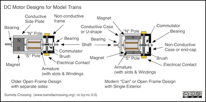
The brushed DC permanent-magnet motor has a rotating slotted armature with wires wound through the slots. Brushes are attached to the fixed outer frame, which rub on the commutator attached to the shaft supporting the armature. Power to the windings passes through the brushes and commutator, which also reverses the polarity of the windings as needed to keep the motor turning. Two forms are typical: older motors had one magnet, with metal on each side to extend the field out. Newer motors use two magnets inside a metal case. The case may provide full coverage (a “can” motor) or may be open like the older design. Regardless, the function is essentially the same, and all of the other parts are unchanged, although some older motors used a different brush material. And, in fact, you can also still buy motors very similar in design to those original ones, although they’re technologically advance compared to the originals.
Although two magnets are used in the newer design, and both have both “north” and “south” poles, the metal case carries the field lines from one to the other, effectively making the whole assembly act like one U-shaped magnet with “north” on one side and “south” on the other, just as in the original.
A motor of this type acts by running electricity through wires wrapped in coils that run through slots on an armature attached to a shaft to create an electromagnet on the moving metal core, and using the attraction and repulsion of that against a permanent magnet fixed to the frame to turn the shaft. More voltage makes the magnetic field stronger, and increases the speed of the spinning shaft. Reversing the voltage reverses the polarity of the magnetic field, and makes the shaft spin in the other direction.
These motors may have armatures with three, five or even seven slots (usually referred to within the hobby as the number of “poles” between the slots, but “slot” is more common technical terminology for motor designers). The armatures are made of a metal, which in modern motors is one of several types of steel. This is still referred to as “iron” because early motors used iron, and steel is an alloy of iron, but all modern armatures for this kind of motor use steel.
Armatures made of metal are formed (for both cost and technical reasons) from flat stamped metal shapes assembled to make the three-dimensional armature. This layering of plates is called lamination, so these are sometimes referred to as “laminated armatures”. The slots may be parallel to the shaft (“straight windings”) or angled (“skewed windings”). Windings are typically designed to handle voltages in the 12 - 24 volt range and to carry currents of 2 Ampere or less in HO and smaller scales (with some exceptions). Note that O-scale will typically use larger motors and likely ones with higher current needs, and large scales (G, etc) always do.
The “magnet” in these motors is a defining characteristic of small motors: in larger motors the magnetic field on the frame is created with windings, but this isn’t practical or necessary for small motors. In the early days of the hobby it was typical to call these “permag” motors, for “permanent magnet”, although that term has largely fallen out of use. In older motors, as shown in the left diagram, one magnet was used, mounted at the end with two metal stampings extending from it on the “north” and “south” sides to wrap the magnetic flux lines out to the sides of the motor. In a modern motor, as seen on the right, two magnets sandwiched inside a U-shaped metal stamping or a metal “can” surrounding the motor do the same.
Brushes and Windings
Two things define this class of motor: the use of brushes to feed power into the windings, and the use of permanent magnets for the windings to push against. Brushes are electrical contacts on the attached to the outer frame that touch contact points (the “commutator”) on the rotating shaft of the motor (the “rotor”) to convey power to the wires (the “windings” or alternately “coils”) that run in loops through “slots” around the lobes of the rotor (collectively the “armature”, which can be used interchangeably with “rotor” to mean the motor shaft and everything attached to it that moves).
Electricity in these wires creates a magnetic field that pushes or pulls against the fixed-position permanent magnets on the non-moving body of the motor (the frame or “stator”). The force pushes the winding wire against the rotor, causing the rotor to turn. As the rotor/armature turns, the commutator contacts move from under one brush to the other, changing the polarity of the current in the winding, and thus the polarity of the magnetic field. So a wire that was approaching a magnet pushing it away suddenly switches to a being attracted to the magnet, once past it, the direction of the current switches again, and the wire is repelled by the nearby magnet and attracted to the distant one. This cycle repeats twice every rotation since there are two external magnetic poles.
At a minimum you need two of these windings, one on each side of the armature, but to really make this work you need an odd number so that attraction is never exactly balanced between the two outside magnets, otherwise the rotor couldn’t be restarted from such a position. Typically model railroad motors have had three, five or, on some larger motors, seven windings (a few O-scale motors have reportedly had nine).
These windings aren’t quite independent of each other (the way they are wound and connected to the commutator can get quite complex), but you can think of them as independent and switching their electrical polarity twice per rotation, which is essentially what happens.
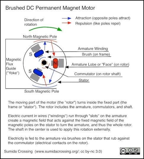
When you look at a motor you see the copper-colored winding wires, and the dark gray metal of the armature that sticks out. This is actually made from layers of stamped metal laminated together, which is why it has fine lines paralleling the direction of rotation. These exposed armature surfaces help to concentrate the magnetic fields created by the windings, and it is these that modelers refer to as “poles”. In a sense they are poles, since they’re acting (some of the time) as one or the other magnetic pole of the rotor. I’m calling them “armature lobes” as there doesn’t seem to be a standard term for them besides “armature” (which applies collectively to the shaft, lobes and windings), although I have also seen “face” used.
The brushes are a fairly important detail. Because these rub on the commutators, which have a curved surface around the rotor shaft, they need to be curved to match it. This is usually achieved by making them out of some semi-soft material (usually graphite with some kind of metal embedded in it) that can wear to match the curve. This implies two things: straight from the factory they’re not making the best possible contact unless they were ground to fit the specific shaft (unlikely), and over time they’ll wear down and need to be replaced. Kato sells replacement brushes, but it’s not clear if the ones provided for North American models would be compatible with their motor designs for Japanese prototype trains; the motors are similar, but not identical, between different models, and Kato’s North American 5-pole motors are slightly larger than the current 3-pole Japanese ones. Brushes are sometimes available for larger motors, although can motors are not typically designed to be serviceable.
Magnets
The magnet is the other key component of a brushed DC permanent-magnet motor. AC motors (and larger DC motors) use electrical windings on the frame to create the fixed magnetic field for the rotating electromagnet on the armature to push against, but in smaller DC motors this is provided by permanent magnets attached to the frame. The strength of the magnetic field produced by these permanent magnets, in combination with the strength of the electromagnet formed by the armature, defines the power of the motor. And since model railroading became an established hobby in the early twentieth century, the simple magnet has undergone a staggering amount of technological change.
The effect of the permanent magnet is to create a magnetic flux though the armature between the two poles of the permanent magnet. This flux is permanent and unchanging (unless something happens to the magnet) and doesn’t actually provide energy to the motor; that all comes from electricity. But it provides something for the armature windings to push against, and the stronger it is, the harder they can push for a given current.
The strength of magnets can be measured in a number of ways, and in a specific motor the strength of the magnetic flux depends on aspects of the motor design (e.g., the gap between rotor and frame) in addition to the magnet itself. But it’s still useful to talk about the power of the magnet on its own, and a typical measure of this is the MegaGauss-Oersted (MGOe), a measure of how much energy can be stored in a unit volume of the magnetic material, an “energy density”, rather than simply a measure of the attractive force.
Early motors used simple magnets of magnetized steel, much like a child’s horseshoe magnet. These weren’t very strong, roughly 1 MGOe by the 1920’s. This meant that they tended to be rather heavy (and bulky). Which wasn’t a problem, since O-scale was considered a relatively small scale at that time.
In 1932 a Japanese metalurgist, Tokushichi Mishima, discovered that an alloy of iron, copper, and Aluminum (Al), Nickle (Ni) and Cobalt (co) made a superior magnet. The alloy was named Alnico in honor of its components, and by 1938 Alnico replacement magnets were being advertised in Model Railroader. They weren’t cheap: a magnet alone sold for US$3, and MRE’s Alnico motor was advertised for $7.50. An early advertisement claimed that an O-scale motor with one was three and a half times as powerful as the conventional motor of the day. Improvements continued and by the 1960’s Alnico magnets had a strength of about 9.5 MGOe.
This had two benefits: for large motors, more strength in the same volume meant more pulling power. But it also made it more practical to create smaller motors. The development of N-scale in the 1950s probably owes a lot to the invention of Alnico magnets.
Alnico went on to have a long history in model train motors, and by 1956 a Model Railroader article could state that “modern motors...all use Alnico magnets”. Alnico was used in some can motors (Sagami replacement train motors c. 1980 were advertised as Alnico motors, likely to differentiate them from cheaper and less powerful ferrite-magnet can motors). Bowser was still advertising Alnico motors as late as 1987.
One problem of Alnico as a magnetic material is that it is both easy to magnetize and easy to demagnetize. In fact, rapid reversal of a strong field (i.e., throwing the loco into reverse without turning down the throttle) will remove some of the magnet’s strength. Over time, motors using them would tend to lose their strength. Hobby stores in the 1960’s offered a “remagnetizing” service for motors, and it was possible for a hobbyist to build a powerful electromagnet to do this at home.
It’s worth mentioning that the armature and the frame magnets make up a system through which magnetic flux flows. One consequence of this is that if you take the armature out (or remove the outside magnet) there’s less flux flowing, and for some magnets this causes a reduction in their stored power. Due to that, after reassembly the motor typically won’t run as well unless it is “remagnetized”. This was more of a factor on older motors that could easily be disassembled; modern ones aren’t really designed to be taken apart, and essential maintenance (brush replacement, lubrication) does not require disassembly. It’s also really only a problem with Alnico magnets, modern ones are less susceptible to such loss.
Ferrite was another magnetizible material, discovered in 1930 in Japan by Yogoro Kato and Takeshi Takei, but not commercialized until the 1950’s. They were being used in DC motors by 1964, if not earlier, but became more common in the 1970s. Ferrite is a ceramic, or rather a family of similar ceramic compounds, made with iron, oxygen and various other materials (barium and strontium are typical). Ferrites aren’t as good as Alnico in some ways, the energy density being less than 4.5 MGOe. But they’re immune to internal eddy currents (an important feature in a motor magnet), inexpensive, and very hard to demagnetize.
Unlike Alnico, ferrite wasn’t something manufacturers bragged about. There isn’t a single advertisement in Model Railroader’s 75-year collection touting “ferrite motors”. Nobody wants to say “my motors are better because they use cheap magnets”, even when it’s true. They were however widely used, particularly in inexpensive can motors from the 1960s onwards (not simply for cost, but also because ferrite is easy to shape to fit inside a can), and are likely still common to this day because they are a good choice for small DC motors.
Rare-earth magnets are the latest development. Discovered in the 1950s, early versions had problems (primarily cost and brittleness) and they really didn’t catch on until the Neodymium-Iron-Boron (NdFeB) form was invented in the 1980’s by Masato Sagawa, yet another Japanese inventor. A modern rare-earth magnetic material can have an energy density of 35 MGOe, ten times that of the early Alnico magnets (or of ferrite magnets). These, too, have been widely adopted in DC motors, although it’s unclear to what extent they’re used in model railroading motors. They are, however, popular in brushless motor designs where the magnet is the moving part, because of their low weight for a given magnetic strength compared to Alnico or ferrite.
Motor Capacitors
Some small motors designed for DC will have a small capacitor across the terminals (usually a small disk). I’d originally thought this was for some power-supply function, to keep the motor working on dirty track, but the typical size is too small for that. The real reason is to absorb high-frequency pulses of electricity created as the brushes make and break contact. This is required for some motors to pass Electro-Magnetic Interference (EMI) regulations. This EMI takes the form of radio waves, which can interfere with radio and television receivers and similar things.
Depending on the design of the motor, such capacitors may not be needed. The need also depends on the specific EMI regulations of the country for which the model was produced. Europe has more stringent requirements than the U.S. at present, for example.
Capacitors, regardless of the reason installed, will interfere with the operation of DCC and need to be removed when converting such models to DCC. This may result in increased radio interference, the consequences of which depend on where you live. In the U.S., the creator of such noise is generally the one responsible for removing it when notified of a problem (and the FCC is pretty good at tracking down significant sources of such EMI, although I’ve never heard of anyone receiving a notice for model railroad systems).
I’ve read, but can’t confirm that leaving the capacitor connected between a DCC decoder and the motor is both unnecessary (because the decoder will mitigate the EMI) and would cause the motor to draw a higher current. I’m a bit dubious about that last part, as it ought to just smooth out the pulses to their average. Although there may be a higher peak current due to “inrush” behavior (an empty capacitor acts like a short) which could harm a sensitive motor-control chip in the decoder. I have not investigated this myself, as I’ve yet to convert a model having such a capacitor.
Note: ferrite coils are sometimes used instead of capacitors, the function is slightly different but also meant to reduce EMI. Here I can see where leaving one in place would affect the output of a DCC decoder, since it’s changing the inductance (resistance to change of current) of the motor circuit.
Important Characteristics of Motors
Motors have two related attributes: speed and torque. The power of a motor (ability to do work) derives from the torque and the speed.
Note: for the technically inclined, “speed” is shorthand for “angular velocity” (𝜔), “torque” (𝜏) is simply rotational force (linear force applied at a distance from the rotational center), and “power” is “motive power”, or the product of angular velocity and torque (P = 𝜔𝜏). Also, “load” here is used to refer to the opposing force the motor’s rotation needs to overcome, as described below.
Speed is directly proportional to voltage: at maximum voltage the motor turns at the maximum speed for a given load. Thus a motor rated for 16V use will turn slower at 12 volts. Speed is measured in revolutions per minute (RPM), and for the kind of motors we care about is typically around 12,000 RPM at maximum voltage with nothing attached to the motor (this varies).
Motor speed is reduced in the gears of the drivetrain, so that the wheels on the locomotive turn much more slowly, but locomotive speed is directly proportional to motor speed for a given set of gears. This is an effect of the gear ratio. A ratio of 7:1 means that the wheel axle will turn once for every seven turns of the motor shaft, and if the motor is running at 7,000 RPM, the wheels are turning at 1,000 RPM. If you reduce motor speed to 3,500 RPM (half speed), the wheels would then be turning at 500 RPM (also half speed).
Run the motor at half speed, and the train moves at half speed. It also is able to pull more, because the voltage (and the power produced from it) is being applied as power over a shorter distance. The geartrain relation is simple, reduce the speed with a higher gear ratio and you increase the power. All other things being equal, a passenger engine would have a lesser gear ratio and a higher top speed than a freight engine, but the freight engine could pull more weight.
Motor speed, while dependent on voltage, is also affected by load. The maximum speed (e.g., 12,000 RPM) is for an unloaded motor. As the motor has more load, it turns slower for the same voltage. The word “load” refers to any force that the motor has to overcome, generally various types of friction. Friction comes from the elements of the drivetrain (which is why good lubrication of the gears matters) and from the friction in the wheel of pulled cars, caused by the number of wheels, the kind of axle bearings, and the weight of the cars sitting on those wheels.
Torque varies as the inverse of speed. At maximum speed, the torque is zero. At zero speed, torque is maximum. Think of it this way: the voltage can either produce speed or torque, as you increase one, the other decreases.
But the ability to overcome friction doesn’t come from simply the speed of the motor. It comes from the power, which is produced from both the speed and the torque. Motor power is zero at both no speed and maximum speed, and it hits its peak at half the unloaded motor speed. The reason is that maximum speed happens at minimum load. As you increase the load, more power needs to be used for the load (the “motive power”), and less can go into making the motor spin.
Current is also important to consider, but this is complicated by the fact that a motor in motion produces “back EMF” based on its speed (back-emf is used by some DCC decoders as a way to measure motor speed and compensate for speed reductions due to load). Back-EMF is effectively subtracted from the needed current. You need more current to bring a motor up to speed, but once there less current is needed to keep it there. However, the more load that is placed on the motor, the more current that is needed. Ultimately it’s the current that’s being turned into pulling power. If you need to pull more weight, you’ll use more power. This is why “stall current”, the amount of current consumed by a motor when you keep the shaft from turning and apply full voltage, is the maximum current a motor can draw, because the motor is doing all that it can to oppose a force greater than it can overcome.
Stall current matters in DCC decoders (and other kinds of motor-driving circuits) because if a decoder can’t handle a motor’s stall current, the decoder will “burn out” if the motor becomes stalled. Since it’s fairly easy to stall a model train motor if you add too many cars or leave a bit of scenery blocking the tracks, this will happen sooner or later.
Motor Behavior and Design
In a DC motor, voltage affects the speed of the motor, and current provides the power of the motor. But it’s not quite as simple as that. The current and power vary for a number of reasons, and some of this depends on the physical structure of the motor. This variation is called “torque ripple”, and it derives from the tendency of the steel armature to be more attracted to the permanent magnets in some positions and the tendency of the armature to want to stay in such a position (called “cogging”). The fixed force that produces this tendency is called “cogging torque”.
You can feel this yourself by turning the motor shaft with a finger: resistance will increase and then decrease, and you’ll feel less of this on a better motor.
However, cogging torque isn’t the only force producing torque ripple. At various points an armature may be approaching a fixed magnet but not yet have changed polarity, and thus be pushing away (slowing the rotation). This happens relatively “far” from the magnet, so the force is weak, but it does have an effect. And the magnitude is affected by the structure of the armature (e.g., more poles or skewed windings may produce more of this force even as they reduce the torque cogging force; we’ll get into that more in a bit).
Torque ripple has the most effect at low speed, because the motor has less angular momentum and thus slows down more in those parts of its cycle where the force is maximized. In the worst case, at very low speeds, it will make the motor stall in certain positions.
Both increasing the number of poles on the armature and skewing the armature will reduce torque ripple, and make the motor run more smoothly. Two of the more often-discussed attributes of “good” motors are an increased number of armature lobes (typically called “poles”) and “skewing” the armature windings. Both of these are attempts to minimize the effect of cogging torque on low-speed operation. But they’re not the only solutions to this problem, and it’s not at all clear that both are needed. In fact, neither may be required with modern motor controllers, but we’ll get to that.
Outside the hobby, motors are typically characterized only by unloaded speed at their maximum voltage, and by their maximum torque. Specifications do not mention torque ripple, or methods intended to limit it, at all. This makes learning about what motor designers do to limit the effects difficult, and to some extent little more than educated guesswork.
What does “Three-Pole” mean, and why should we care?
The word “pole” as used by hobbyists refers to a magnetic pole, and specifically a magnetic pole on the armature. The term itself is model railroading jargon. It has a specific meaning inside our hobby, even though it is not the same terminology used by a DC motor designer (referring to “slots” as a way to count bundles of windings is more common outside the hobby, but still rare).
Technically, what we mean by a pole is the number of places where windings wrap around the armature, or equivalently, the number of “lobes” of the armature that stick up between them. This will always be an odd number of three or more “poles”, and both three and five-pole motors are typically in N and HO scale. Seven pole motors are sometimes found in O scale, and in the past motors have been made with up to nine poles.
A lot of ink has been spilled over the years on the question of three-pole versus five-pole motors. It is widely known among hobbyists that motors with more poles are “better” than ones with fewer poles, for some reason having to do with low-speed operation. What is the underlying issue here, and how relevant is it today?
The basic benefit is that more poles make for less variation in the attraction between the moving magnetic poles on the armature and the fixed magnetic poles on the frame (i.e., less torque ripple). This improves low-speed running. Life is rarely that simple however.
The armature of a brushed DC permanent-magnet motor has wires wound around it that pass through slots in the armature. The non-slot portions of the armature stick out to almost touch the faces of the outer magnets (or the steel leading from them), to provide a minimum-distance gap for the magnetic flux to cross. There’s a fundamental trade-off between the amount of space devoted to wires (the slots) and the amount of space devoted to flux (the armature faces, or “poles”, that stick out). But for a given ratio of slot to pole size, you can distribute this across two or more slots (and the same number of poles). Thus a five-slot motor has, in theory anyway, the same ratio of wire to flux, and merely rearranges it.
In a typical low-voltage permanent-magnet hobbyist motor, the flux is not evenly distributed around the outer frame the way it is in larger motors. Instead it is concentrated where the magnets or their metal extensions come closest to the armature. This is about 20 - 30% (on each side) of the circumference of the motor. A five pole motor spreads the armature flux across five faces, while a three-pole motor uses three larger faces. This will cause the intensity of the flux through the armature to vary as it rotates, and to vary more with a three-pole design than with a five-pole design. Hence, “five pole” motors reduce torque ripple and improve low-speed running.
The converse of this is that more slots means fewer wires per slot. In an ideal world, this wouldn’t change the total number of wires assuming the slot/face size ratio was unchanged, but in practice it almost certainly makes it harder to wind as many wires onto the armature without losing some of the flux-producing face, and thus more slots mean either a smaller number of current-turns or a more concentrated flux (which has limits of its own). For the same current (and you can’t make it larger without changing other things) this means less force, and thus less torque, with a five-pole motor than with a three-pole motor.
There is a lot of complexity to these trade-offs, and a motor designer may sacrifice one aspect to improve another in ways that can’t be simply summarized based on the number of slots. To say that all three-slot motors have less torque than a same-size five-slot motor is almost certainly untrue. Individual designs will vary and be more or less optimum based on the amount of metal used in the armature, its shape, and the ability of the manufacturer to fit more windings into that shape.
More practically, it’s harder to wind wires through more slots, without breaking wires or failing to pack them all in before running out of space, which increases the number of motors discarded for being improperly wound. The net effect is to make motors with more slots more expensive.
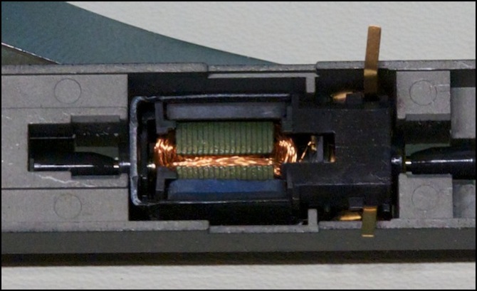
Kato 5-pole motor, showing the windings (copper wire) and lobes (gray metal) between the permanent magnet poles (blue and black metal slabs)
Hobbyists and the model train industry go back and forth on this aspect of motor design. The earliest motors from the 1930’s were apparently three-pole (although some, particularly in O scale were five or even seven-pole designs), but five-pole models became common for HO after the war. When can motors were introduced, many cheaper ones were three-pole, and this subsequently led to a rediscovery by hobbyists of the benefits of five-pole motors. In N-scale, three-pole designs were fairly common due to the small size of these motors, although in recent years five-pole designs have become typical, at least in the U.S.
The number of poles seems to be more of a concern in the North American market than in Japan, and Japanese manufacturers even today don’t typically advertise their motors as being “five pole” at home, although stores in the North American market will call this out (at times incorrectly; I found one reported instance where a well-running HO motor advertised as “5 pole” was found to be a “3 pole” design when someone finally disassembled one).
What’s Skewed?
Simple motors have the windings arranged so that the slots run straight along the shaft, as seen in the photo above. In a skew-wound motor (also known as a twisted-slot motor), these twist around the shaft slightly, so that there is an overlap of the end of one face relative to the next. This helps to reduce the problem those gaps between windings cause by evening out the push/pull force as the shaft turns. So the skewed design is another method for improving low-speed operation by reducing torque ripple.
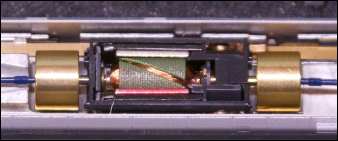
Kato’s 3-pole skewed-winding motor, used on “DCC Friendly” trains c. 2007 and later (with flywheels)
There’s likely some additional inefficiency in skewed windings, as the overlap would likely mean that the lobe will be on the external magnetic “wrong” side of the pole longer, and thus pushing in the wrong direction. In practice, this doesn’t seem to be a problem: installed in a train with a DCC decoder producing PWM (which results in about a 25% speed reduction) on my Zephyr (so about 13V PWM at the motor) the motor shown above ran at 14,000 RPM with the wheels in the air (maximum speed also depends on torque). That’s as fast as any I’ve measured. The drivetrain has a 12:1 ratio, and the wheel diameter is 5.55mm, so that equates to 183 scale kph (114 scale mph); faster than most of these trains could run in real life, except for the Shinkansen (bullet train) models.
The bottom line is that skewed windings are likely to reduce torque ripple in the real world, possibly at a loss in maximum torque. In other words, they perform much the same function as adding poles (slots), and may be prone to the same problems with torque. But whether either effect is greater in a skewed-winding motor than it is in a five-pole motor is less than clear. It probably depends on the specific design choices used, and thus in some motors skewing is better than adding poles, in others adding poles was a better choice.
Some motors have both more poles and skewed windings. This almost certainly leads to further reduction in cogging, and thus to superior low-speed performance, but the likelihood is that it also leads to less torque, which would mean less pulling-power.
Flywheels
Outside of the motor, it’s also possible to compensate for torque ripple mechanically by using one or more flywheels external to the motor. Since flywheels store angular momentum, and what we’re ultimately concerned about for keeping the train moving is angular momentum produced from torque, a flywheel will help to smooth out the variations by maintaining speed, in the same way that a capacitor smooths out electrical ripple by storing energy from current peaks and releasing it during current sags. However, at low speeds when torque ripple is a more serious issue, the total momentum stored in the flywheel is much less since momentum depends on velocity. Thus their benefit for smoothing torque may be limited. Flywheels do have other benefits though, and any added benefits for reducing torque ripple essentially come for free.
Model railroads are far from an ideal environment for motors. Track and wheels both get dirty, which interferes with their ability to conduct electricity. Sectional track has small gaps between sections where wheels make poor contact, and there are things like switches and crossovers that also have gaps where no power is available at all (to avoid short circuits). Track can be uneven, causing wheels to make poor contact with the rail. All of this means that power that should be a constant voltage may vary (as dirt or gaps increase the resistance between the track and the wheel) or even fail altogether in some places. A moving train will typically coast past the problem area, but since there is a lot of friction in the gears between the motor and the wheels, and because it is pulling a load and needs torque to counteract that drag, it will also slow down quickly whenever the voltage it receives drops.
Motors themselves have very little mass in the moving rotor, for all they they’re made out of fairly dense metal. A flywheel is nothing more than a big chunk of metal, typically brass, attached to the motor shaft to increase the moving mass of the motor. Because moving mass stores energy (a rotating mass has angular momentum) more mass means more energy to overcome the friction in the gear train and the drag of pulled cars, meaning the train will coast further when it loses power. Put another way, a brief loss of power will cause less decrease in the train’s speed if the motor has flywheels. That same effect also compensates for small variations in the motor’s output due to its geometry (i.e. compensates for cogging).
Like many things in the hobby, flywheels themselves are a source of contention. Some modelers worry about the risk of added wear to motors that could come from one that was out of balance (which seems rather implausible to me as long as the flywheels were properly machined). Some feel they add unnecessary lag in responsiveness by adding momentum. That’s more of an issue for larger scales, as you’d likely need near-perfect track and drivetrain mechanisms to observe that with any flywheel that would fit in an N-scale locomotive or motor car. And some feel that while not harmful, their advantages have been overhyped, which is probably true, at least to some extent.
Too much momentum could be a problem. If you want to stop the train and it keeps rolling it could hit something that you were trying to avoid. But in most cases the problem is too little momentum, and flywheels are a way to overcome this by evening out short-lived variations. On really good track they may be unnecessary, but how many of us have really good track everywhere? In large scales, very large flywheels may store too much momentum for safe braking, but this is not likely to be a problem in N-scale.
Digital Control Systems
The final question regarding torque ripple is “do we even need to care about it today?” When motors were controlled by a fixed voltage, and low speed meant setting to the voltage to a level at which torque ripple wouldn’t stall the motor, finding ways to minimize torque ripple mattered quite a bit. And, if you’re using a DC “power pack” to run trains, it still does.
But by now, many modelers (I’m not quite ready to say “most”, but we’re getting there) use DCC. And DCC uses decoders in the trains that include digital motor controllers. One of the benefits of digital motor control is the ability to sense motor current and adjust voltage to keep speed constant. This is generally referred to as “Back-EMF”, because the variation in current with speed is the result of back-emf produced in the motor. Not all decoders include “Back-EMF” speed control, but it’s increasingly common. I wouldn’t buy a decoder that lacked it today.
A digital motor controller can sense current thousands of times a second. I don’t know how often they actually do it, that’s proprietary to the designers of the decoders and they don’t document it. But since most decoders these days issue PWM pulses hundreds of times per motor rotation, they certainly could react fast enough to adjust voltage on the fly to reduce cogging.
My entirely subjective observation, from a sample of two of each, is that there’s much less cogging from Kato’s five-pole straight-armature design than from their newer three-pole skewed-armature design. However, I was also comparing two different sizes of motors (Kato’s 3-pole motors are smaller than the 5-pole motors they use in North American N-scale locomotives), and that could have had an effect, although I would expect it to have increased cogging in the larger motor, not decreased it. I suspect the reason I felt less with the 5-pole motor is that there’s less metal in each lobe, so there’s less attraction between it and the permanent magnet. That may well be why they added flywheels with the newer motors.
But in any case, Kato’s Japanese models that are “DCC Friendly”, despite using five-pole motors on earlier models (and on ones for the U.S. market), reverted to a three pole design. And that begs the question: why would they take the backwards step of using a motor with more cogging?
This could simply be because those are domestic models and the Japanese hobbyists don’t care as much about low-speed operation as do North American hobbyists (their export GG1 model is “DCC Friendly” but uses a five-pole motor). But it may be an indication that their EM13 decoder, which was designed by Digitrax, is compensating for torque ripple. Proving this would require capturing PWM behavior on a sub-millisecond scale over an extended interval. I have not done that as yet.
Summary
Clearly a flywheel-equipped, five-pole, skewed-winding motor is likely to have very low cogging. But you may have sacrificed a good bit of torque to get that. And it’s equally possible that a good designer could have produced a similar result with a three-pole skewed motor or a five-pole non-skewed motor, without flywheels. In the end, you can’t make gross generalizations about something this complex. All you can do is bench test a model pulling real cars (or a load simulating real cars in motion, not stalled) and state “this model runs at a minimum speed of X with a pulling power of Y” (the latter in grams or ounces, since pulling power in “pulled cars” has its own sources of error). Very few reviewers get that detailed, and none compare the operation on PWM to DC that I’ve seen. Most do at least use regulated 12V DC, which has the benefit of being consistent even if very few of their readers will actually run trains on pure, filtered, DC.
