


DCC Japanese Prototype Signals
Trains operate along tracks under the control of signaling systems in most modern passenger railways, and this is particularly true in Japan, where several serious train accidents in the 1950’s, 60’s and 70’s drove home the need to keep trains carrying hundreds of people away from each other and from problems on the track. Signaling systems can transmit information directly to the train operator, and this is often used on high-speed lines or other systems where there is a need for immediate response to problems. But most commonly, signals use colored lights at intervals along the track.
Signals, whether line-side or directly communicated (“cab signals”) are structured around the concept of a block, essentially a length of track, usually connected to an “occupancy detector” of some kind that can report when a train is on the tracks within the block, and with a signal at each end controlling access into it (or at one end, if travel is always uni-directional). Each signal consists of one or more sets of colored lights, each set called a “signal head”. The combination of colors displayed by the heads can be much more complex than the simple red/yellow/green of a traffic light, and these are called “aspects” of the signal. For more on typical Japanese signal aspects, see my Japanese Railway Signaling page, and for some examples see the Example Signals page.
I want to have lineside signals along the commuter/express line. For the rapid/shinkansen line I’ll replicate cab signals, which will use the same control systems as the lineside signals, but omit the actual signal masts and signal-driver electronics (more on that another time). I may eventually add signals on the subway, but since most of these would be out of sight in normal use, it’s not a priority.
Note: This page describes current plans, which have not yet been implemented. There may be errors in my understanding of how these things work that won’t be discovered until I get to the implementation. Also, in the summer of 2011 JMRI implemented support for signal logic that may allow me to avoid using scripts to control signals. This page has not yet been updated to reflect those capabilities.
Signal Control
While it is possible to build a self-contained signal system that can set the aspect (color) of the signal head based on occupancy of adjacent blocks, and several vendors (Kato, Tomix) provide such systems for DC layouts, this falls short of the full richness a signal system can provide. Usually these only provide for red/yellow/green aspects. These systems are also incompatible with DCC control, since they depend on occupancy detectors designed for DC-powered track.
In a real railway signal system, the signals are sensitive not only to block-occupancy detectors (which can also detect broken rails), but have additional input from other sensors that report hazards on the line (landslides, undermined track, water), as well as being aware of conditions such as switch (turnout) setting, and route assignment. And dispatchers may override the system (within limits) to force a stop or clear a hazard warning.
DCC provides the potential to both control signal indications, and to do so based on occupancy, turnout setting, and manual override. To do this, signal heads need to be powered by a system linked into the DCC control bus, and other systems (turnouts, occupancy detectors) need to report information to a control system that is also connected to the control bus.
The open-source JMRI program includes capabilities that can be used to build a signal control system, including the ability to have programs or scripts executed when sensors (occupancy detectors) or turnouts change state. It also provides for control over signal heads, so scripts can do things like “when turnout X is thrown or block Y is occupied, set signal head N to RED” (the actual scripting language isn’t that close to English, but it’s not particularly complex).
However, JMRI only understands the following signal aspects: Red, Yellow, Green, Flashing Red, Flashing Yellow, Flashing Green and Dark. This misses a few used in Japanese railroading: Yellow over Yellow (YY), Yellow over Green (YG) and Green over Green (GG). The latter is only used by a couple of lines, as an indication for “Clear for >130 kph operation”, so it won’t be necessary for my commuter/express signaling. But YY is a common aspect, so I’ll need to find a way to represent it. The easiest is probably to treat the five light signal used for YY, YG or GG as if the two lower lights are on a separate head. Thus Yellow would be “Yellow” plus “Dark” and Yellow-Green would be “Yellow” plus “Green”. But perhaps I can do better.
With the Digitrax DCC system I’m using, I need the following to make this work:
- A computer running JMRI (I have an old iMac I can use for this).
- A computer USB interface to the Digitrax LocoNet control bus (RR-CirKit Locobuffer-USB).
- Turnout controls that interface to LocoNet (Digitrax DS64).
- Occupancy detectors that interface to LocoNet (Digitrax BDL168).
- A signal driver (controller) that connects to LocoNet.
Except for the signal driver, all of these are things I either have or was already planning for other reasons. For the signal driver, Digitrax makes the SE8C (about $100, not counting wiring), which can control up to 32 signal heads. The SE8C provides for red/yellow/green/flashing-yellow aspects, and can also drive multi-LED position signals, needed in Japanese signaling for “repeater” signals.
Alternatively, the RR-CirKit TC-64 ($109) could have been used. The TC-64 can drive up to 32 heads directly (8 sets of 4). The TC-64 is more flexible than the SE8C, and can light any LED constantly or blinking (it also has a “dark” aspect). For a repeater signal, which requires driving three LEDs off one output, the 4ASD-4 ($21) is needed, which supports up to four heads. This doesn’t increase the number of signal heads per TC-64 output, but it does increase the voltage per output to allow three LEDs to be driven.
All things considered, the SE8C would appear to meet the requirements for displaying Japanese signal aspects at the lowest cost. A head with more than three lights would need to use two of the SE8C’s “heads”, but this is true of the TC-64 also. With four-color heads, this works out to about $6.25 per signal head (not counting the other components, the power supply, or the actual signal mast and LEDs). Even with a substantial number of blocks, station signals, and perhaps some repeaters, I’m only going to need one or two of these to signal the entire commuter line (I might add signals to the subway later, but the rapid/shinkansen line will probably replicate a cab-signaled line, and not have lineside signals).
So here’s the plan:
- Occupancy detectors and turnout controls will report status changes to JMRI via LocoNet.
- Each signal head will protect a single block (as on the prototype).
- JMRI control scripts for each block will set the aspect of all signal heads that protect the block.
- Signal drivers (under control of the JMRI scripts) will light the appropriate LEDs to display the aspect.
All this needs (aside from off-the-shelf electronics) is a bit of very simple script programming (I can do that), and one heck of a lot of signals (about 16 block/station signals with three or four lights, eight station entry signals, and possibly one or more repeater signals).
Signaling Practice for Sumida Crossing
I’m going to use four-aspect signals on my commuter line, following the “type A” design noted on my Japanese Signaling page. These allow for indications of “stop” (Red), “25 kph” (Yellow-Yellow), “~50 kph” (Yellow) and “full speed” (Green, meaning 130 kph for commuter/rapid and express trains). I could have used the five-aspect signals, which add a “75 kph” option, but these require an extra block, and my line is too short between stations for this to be reasonable. Even four aspects is a bit of a stretch, but I want the very non-North American look that four-aspect signaling will give.
Stations will have entry signals, which are going to be a pair of signals on stations with a siding (the upper signal controlling the main, and the lower, offset, signal controlling entry to the siding). For these, I expect to use two-color (Y/R) signals, as entry to the station would be at restricted speed.
Signal Suppliers
Kato makes a three-aspect signal (20-605), but it works with track sensors intended for DC use. Tomix makes two (5565), three (5564), four (both kinds, YY 5562 and YG 5561) and five-aspect (5560) signals, but these are intended for use with their DC-based TCS systems. Both of these could be modified to be driven by the SE8C or some other DCC-compatible system, with a bit of surgery (see References section).
The Tomix model is the only way to get Japanese four- or five-aspect signals commercially made. For two-head and three-head signals, any North American prototype signal of similar appearance (i.e., one head with lights arranged in a vertical row with an oval surround) could be used (e.g., Tomar, NJ International, etc). And for repeater signals (position signals using yellow lights), a Pennsylvania Railroad position-light signal (e.g., NJ International) could be used.
Given the cost of commercial signals, I think I’ll try my hand at scratchbuilding what I need with 1.5mm LEDs (Miniatronics sells these, although I could order bulk from an electrical supply company) and plastic or brass tubing/sheet.
Signal Wiring
I’m going to use Digitrax’s TSMK, which has built-in resistors and takes its power from the SE8C. The manual for the SE8C claims that it only needs 100 mA at 15 V DC (which works out to 23 mA per signal head at 2 volts, so it should be enough to light a LED). The power supply (if large enough) can be shared by other SE8C and BDL16 devices (a BDL168 also needs 100mA).
The following diagram shows the expected wiring for a four-LED, four-aspect, signal. As noted on my Japanese Signaling page there is more than one arrangement of four-light signal heads, but this is the one used for the signal that can display the Yellow-Yellow “Restricted Speed” aspect.
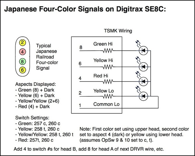
The output of the SE8C (no matter how the signals are connected) is a 5V DC signal. This means that the 100 ohm resistor in the TSMK (and also in the signal base, if I were to use those) is sufficient for a typical 2V, 30mA LED. If I were using LEDs limited to 20mA (or wanted to underdrive them) I’d need to add more.
Wiring will (I expect) be 32 ga magnet wire. I measured a resistance of about 0.2 ohms/foot (over ~200 feet), although a source I found says 0.164. Even with several feet of wire per signal, this won’t noticeably alter the resistance compared to the TSMK’s built-in 100 ohms. That source also says that the current carrying capacity is 90 mA if the wire is tightly confined, or 0.5 Amps if run in air. Even with two active LEDs sharing the common, I should not exceed 90 mA, so using several of these wires within a signal post should be fine.
The SE8C has eight ribbon-cable connectors. Each ten-conductor ribbon cable can connect to two TSMKs (one in “orientation A”, one reversed, or in “orientation B”). A single TSMK can control one four-aspect signal (using both heads) or two signals of two to three aspects (using one head each). Note: a single TSMK could also control a five-light, six-aspect signal (Y-Y/Y-G/fY-G, plus R/Y/G) or six-light, seven aspect (all the above plus G-G) if I were going to use any of those.
Actually, when using only half a TSMK (upper or lower head), two TSMKs in the same orientation can be connected, you just can’t use the same half of more than one TSMK in the same orientation (in other words, you get four heads per wire, and a TSMK can control one or two heads). Net result: I’m going to get 16 four-aspect signals per SE8C.
Actually, what I need are four-aspect signals on blocks, and two- or three-aspect signals on station platform entry signals. I’ll be using unidirectional signaling on the Commuter line, and will have three sidings (the two half-sidings on the Riverside Station count as one since one only has an exit signal, and the other only has an entrance signal). Each siding exit signal is also a block signal, and should support the yellow-yellow aspect. The station entry signals (one for each track) only need to show Red/Yellow (siding) or Red/Yellow/Green (main), so one head per track is needed.
I’ll have 12 block signals (counting station exit signals as a block signal), but four of those will be station entry signals. So that’s 8 four-aspect signals, plus three more station exit four-aspect signals for the sidings (11 signals total, 22 heads), plus seven two-aspect station entry signals (7 more heads). Or a total of 29 heads, out of a possible 32. So I should be able to fit them all on one SE8C. In fact, I can use the remaining three.
The SE8C has sufficient power to drive a position-light signal off a single head. Since these are used as “advance” signals in congested areas, I may use a pair of these on approach to the Riverside Station, since the track makes an abrupt curve before and after the platform. The one on the “counterclockwise” path will need two heads, since the diverging route gets a separate signal. Thus I need three more heads (29+3=32).
LEDs for Signals
There are two major kinds of LEDs I could use for n-scale signals: a 1.5mm LED with leads, or a surface-mount (SMD) LED, which has solder points to which wires can be (carefully) attached. Although 1.5 mm is about the correct scale size for an n-scale signal lens, the leads stick out to the side, and should not be bent close to the LED, which makes it hard to fit them within the space behind the signal head. Surface mount LEDs, despite the extra difficulty of soldering to them, seem to be the appropriate answer.
Some that I’m specifically looking at:
OSRAM TOPLED, 120° viewing angle, round 2.4mm clear lens
LY T68B-T2V1-26-Z Yellow (30 mA @ 2.1V), 628 mcd
LS T67B-T1U1-1-Z Red (30 mA @ 2.1V), 420 mcd
LP T655-Q1R2-25-Z Green (30 mA @ 2.1V), 126 mcd
Kingbright, 120° viewing angle, rectangle (1.3 mm x 1.25 mm)
APT2012ZGC Green (20 mA @ 3.3V), 300 mcd
APT2012YC Yellow (20 mA @ 2.0V), 150 mcd
APT2012SURCK Red (20 mA @ 1.95V), 150 mcd
References
Websites
JMRI Logix page - Describes the “take action on condition change” capabilities of JMRI.
JMRI Signaling Page - Provides an overview and links to other material.
Equipment Manuals
Digitrax SE8C Manual. (PDF)
RR-CirKit TC-64 Manual. (PDF)
RR-CirKit 4ASD-4 Manual. (PDF)
Other
Converting Kato and Tomix Signals to DCC operation (Japanese page)
