


A Simple Design for DCC Lighting Flicker Prevention
To recap, this design is intended to work in typical N-scale DCC systems with voltages around 12-14 Volts, but has a safety margin to allow use on any standard DCC system up to 22 volts, which would also protect it when used in DC systems (some fairly common examples of which can have voltages of 22 Volts at maximum). The system is also designed specifically to match Kato’s LED-based interior lighting, which uses a surface-mount LED with a power draw of around 3 mA. It would not work with standard 20 mA LEDs or 60 mA bulbs. The design is intended to allow a large number of cars (15 per train) to power-up simultaneously without tripping a DCC circuit breaker.
Note: Larger versions of the images here can be found in the Car Lighting photo album.
There’s more than one solution to this problem, and I started with a more complicated Regulated Voltage design, but a number of factors (primarily available space and the impact on runtime) made me move away from that design. What I ended up with was a circuit stripped to the bare bones:
I’m not the first person to come up with this general idea for lightboard power protection, and several similar designs for general car lighting are noted in the references section on the overview page. After I started work on the voltage regulator design I was influenced by those, and that led me to consider this approach. I’m not aware of anyone else doing this for Kato’s lightboard specifically.
I’ll go into more detail about the component selection below, but first an overview of how it all works.
Circuit Summary
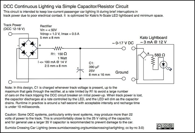
The rectifier on the left converts the DCC on the track (which is a form of alternating current), taken from the two brass input rails that normally feed the lightboard, into simple DC, with a peak voltage about 1 volt less than the DCC voltage. The resistor limits the charging current to avoid tripping the command station’s circuit breaker when a large number of cars equipped with these are on the track at the same time. And a capacitor stores energy (and smooths any pulses in the input current), discharging it when needed to maintain power to the LED lighting.
The resistor limits the initial current used to charge the capacitor to less than 0.1 Amps per board (it varies depending on the track voltage and is about 85 mA @ 14V). That means that even 15 cars would only draw around 1.3 Amps on initial charging or recharge, well below the current needed to trip the circuit breaker. On systems with higher voltage more current goes through the resistor, but 15 cars would still be just 2.2 amps at the maximum standard track voltage of 22 volts. The resistor has one significant drawback, and that’s that it will also drop the voltage that is available to the LED by a volt or two, depending on the capacitor voltage and LED current draw.
Another advantage of this circuit is that it’s simple and compact. The capacitor is always going to be the largest component, and the other two are relatively small, but still large enough to be visible when placed within a typical commuter car. Additionally it will provide current to the output for a longer time, as the capacitor can drop all the way down to about 2-3 volts before there is too little voltage to light the LED. The disadvantage is that there will be a significant voltage change when the track power is lost, as input to the LED drops by as much as 20% for the Kato lightboard (and loss would be greater for a 20 mA LED). The light intensity will also degrade from that point as the voltage quickly drops from ~8 volts to the point at which the LED goes dark. While intensity changes aren’t as bad as outright failure, they’re still likely to be noticed. In practice, this did not produce a noticeable fluctuation.
One potential problem is that nearly the full DCC voltage (less the rectifier loss of about 1.0 volts) goes to the LED normally, meaning it’s going to be quite bright. One of my complaints with the lightboard used alone on DCC is that it’s too bright normally. Having the resistor between the rectifier and LED reduces this a little, but the voltage drop for the Kato lightboard’s current is probably just half a volt. As I noted in the overview, once the interior of the car has been detailed, the light appears much less intense than it does bouncing off the usual beige interior, and so I no longer consider this an issue.
The first limit is that I’ve optimized for the Kato lightboard, which means I need to support at most a 3 mA normal current (I assume 5 mA to allow for component variation). The second is that I’ll assume a DCC environment limited to under 22 Volts, so that I can use 25 V capacitors (the next common size is 16 V, and while that would work on some systems, the safety margin for typical 14 Volt DCC systems is too small for comfort; when capacitors fail, it tends to be damaging to things around them, and I don’t want that happening in a car I could only replace by buying a $50+ expansion set). I’d be happier with a 35 V capacitor, but those became too large and/or expensive.
I wanted a small capacitor, and after looking at a number of alternatives and optimizing for cost and size amount the available ones, I ended up with a 100 μF Tantalum Surface-mount capacitor a mere 8mm in length and 4mm in width/height. At $1.73 in quantity 100 it was the most expensive component by far, but still quite reasonable compared to Kato’s lightboard, which typically cost $5 or more each. This model was rated for 2000 hours of operation, which is fairly typical but less then the best (8000 hours) I could find if size wasn’t as much of an issue. In practice, I think it’s going to be a long time before any of my cars racks up 2,000 hours of operation, and the circuit boards I’m building are cheap and easily replaced. Run time with this was much longer than I’d anticipated, and very well suited to its task.
In order to limit inrush current to 100 mA at 14 Volts, a 128 Ohm, 2 W resistor is needed. I can drop the resistor to 1 W by increasing it to 150 Ohms. With a rectifier, this will drop the voltage on a 12 V DCC system to about 10 volts, which is acceptable. Optimizing for size turned up a 2.5mm x 8mm resistor. And so, I’m left with the following as my parts list (prices are for quantity 100+, as I’m going to be adding these to a lot of cars):
Parts:
- Rectifier: Fairchild Semiconductor 58K1812 ($0.219)
- Capacitor: KEMET T491X107K025ZT, 100 μF Tantalum Surface-mount ($1.73)
- Capacitor: (alternate) Panasonic EEUFR1E391L, 390 μF Electrolytic ($0.254)
- Resistor: Vishay PR01000101500JR500, 150 Ohm, 1W, 350 V, 5% ($0.076)
Note: the capacitor listed above was discontinued by the manufacturer. As of early 2017, Digikey has a replacement, part T491X107K025AT, with a slightly higher price. I haven’t checked the other parts, and only noticed this one because a reader comments on it.
Caution: if adapting this circuit for larger scales, I recommend using a larger capacitor rated for at least 35V, and 50V would be preferable. It’s a good rule of thumb that capacitors should be rated for twice the expected voltage, and DCC voltages can get into the mid-20’s. Capacitors fail destructively when over-voltaged, and I don’t think you want that happening inside an expensive model.
The Panasonic is a big but inexpensive cylindrical capacitor with an 8000 hour life. The Kemet is a more expensive, and lower-capacity, surface-mount model that is easier to hide inside the car. I’m going to use the Kemet, but I’m listing the other here in case you want to optimize differently.
Design Alternatives
I could add the regulator and output capacitor of the Voltage Regulator design to this, but the more I think about the implications in terms of operating time (drastically shortened by the 7 volt regulator) and space (not as big as the capacitor, but still substantial), the more I’m willing to accept some lighting fluctuation if it will minimize complete outages. And it turns out after testing the regulator design, that it doesn’t provide the constant-intensity lighting that I’d expected, although I don’t know why. Also, for typical outage durations, no variation in intensity is perceptible with the unregulated design shown here.
With a small enough value for the capacitor, and a large enough value for the DCC system’s circuit breaker, I might have been able to eliminate the resistor. This assumes that the transient current is short-lived enough that it doesn’t damage the regulator (they have fairly high resistance to very short-lived currents, typically several times that of the possible current). And it is even possible that the resistance of the regulator itself would be sufficient to limit the current, however the numbers suggest that the limited current would be quite high, up to 50 Amps, which seems too high to avoid tripping the breaker even if its only on for a short time. In the interest of avoiding problems with component lifespan and accidental circuit breaker trips, I kept the resistor in the design.
The other issue was capacitor size. Limiting the capacitor diameter to 8mm to fit easily in the car interior, and looking for the largest capacitance I could get in a reasonable length with a long service life, led me to several options of either 330 μF or 390 μF. The available ones were all 15mm in length (a couple around 10mm had half-year lead times from Newark), with the best choice being the Panasonic EEUFR1E391L, a 390 μF capacitor rated for 8000 hours @ 105°C; a rather long life, and at $0.254 in quantity 100+, a reasonable price. It was still large enough to be obtrusive, and the power capacity was quite low, but at a 5 mA draw my estimate was that it should discharge to 36.8% in 49 msec, which is fairly long. In practice, it turned out I was getting quite a bit more, and thus could use a smaller capacitor. As noted, I settled on a 100 μF surface-mount tantalum capacitor, which worked quite well.
The rest of this page outlines the selection of the various components, and how I ended up with the values summarized above.
Capacitors
One big question that arose was: how much time do I need to keep the lights on, and can I get a capacitor with enough storage in the space I have? I could fit about a 10mm cylindrical capacitor, which limited me to 560 μF, although an 8mm one was more practical and that limited me to 390 μF, but a 100 μF surface-mount model was much smaller, and turned out to be adequate.
This was a tantalum surface-mount capacitor. These are available in the 100 μF size (and a few up to 220 μF). They have a significantly higher cost than cylindrical electrolytic capacitors ($1.50 to $10 in quantity 100), but are typically in a rectangular 2mm x 4mm x 7mm size, so they could be laid flat, below window level. Endurance would be somewhat worse however, typically around 2,000 hours (versus the 8,000 hour long-life electrolytic model noted above as the alternate), but that’s still a substantial number of years in daily use, and likely a lifetime of infrequent use. Heat is also a factor due to the compact design.
Because of the small size, heat dissipation in operation is a factor to consider when working with surface-mount capacitors. The model I ended up with had a maximum power dissipation of 165 mW, which means no more than 16.5 mA average. But since normal discharge in the Kato lightboard is less than 5 mA, that means it should be fine even with relatively frequent discharge/recharge cycles.
Aside from the cost, however, availability is a problem, as the less expensive ones are currently (Fall 2010) showing lead times of several months on Newark, and I’d rather not be paying $10 - $20 per car just for the capacitor. However, I’ve found one from Digikey that’s in stock and with sufficient volume that it will likely stay that way for a time. This one has a 2,000 hour service life. And with a price point of $1.73 in quantity 100 it’s affordable, and preliminary tests showed that it worked well.
Voltage Rectification
Kato’s lightboard will run on DCC, but I can’t have the capacitor feeding power back to the track, and most capacitors are polarized anyway, which means I need a pair of diodes (at a minimum) to convert the track power into DC and prevent backflow. And it’s actually easier (in terms of space) to use a small full-wave rectifier (four diodes in a case).
A rectifier will convert the square-wave DCC signal to an ordinary DC voltage. Typically this is a diode bridge that will drop the input voltage by about 1.2 volts, although careful selection can get that as low as 1 volt. Thus a track voltage of 12 V DCC, which may degrade to about 10 volts on the rails, would be dropped to as little as 8.8 - 9.0 volts. The worst case of 22 volts (the maximum allowed per the DCC standard) still needs to be accepted as input, but that’s not a serious limitation as most semiconductor rectifiers are rated for 50 volts or more.
One concern I’ve seen raised is that in a DCC environment, a rectifier with a slow switching speed might draw excess current (which would mainly be wasted as heat). This stems from the fact that cheap silicon diodes have a high “reverse recovery time”. However, “high” means “several microseconds (I saw “6” mentioned in a post, and elsewhere have seen “hundreds of nanoseconds”). DCC operates at a frequency around 16KHz, meaning that a cycle is about 60 microseconds long, and thus switching time needs to be significantly below 30 microseconds. The data sheet for my selected rectifier doesn’t note the type of diode used. Switching times of 6 microseconds would probably be at the high end of acceptable, but “hundreds of nanoseconds” would be fine. Since I’m not seeing excessive heating in the rectifier, my suspicion is that this model works “fast enough”. Typically a rectifier will use Schottky diodes, which have reverse recovery times that’s effectively instantaneous, and I suspect that’s what I have here.
The model I bought for the prototype was in a fairly small 4-pin IC case, but a surface-mount (SMD) case is what I used for the final design (the one specified above), both because it is smaller and because it will provide better electrical specifications, although it requires me to be more careful about soldering. Assuming I can solder well enough, that means I’ll have a 1.0 volt drop across the rectifier. I’ll use that for all my later calculations.
Note: even with my thumb-fingered soldering, I managed to solder to the surface-mount rectifier’s leads without melting it (generous use of heat-sink clips no doubt helped), so surface-mount it is. Also, if conductive glue is to be used instead of soldering, this becomes less of a concern.
Inrush Current Limiting and Resistor Sizing
When power is first applied to the track, the capacitor will draw power at a high rate as it charges up to the voltage of the track. This creates a short-lived but very high current (called an “inrush current”), as the capacitor initially acts much like a short-circuit. This problem increases with larger capacitors. With a number of cars equipped with this lighting circuit on the same section of track, the aggregate current may be high enough, and sustained long enough, to trip the circuit breaker. It could also damage the voltage rectifier by overheating it, although given the short duration that’s unlikely unless there are a large number of back-to-back complete outages. Still, better to be safe.
Note: with each car drawing around 100 mA from a cold start, and thus each train drawing about an amp, I need to be careful that the number of trains being powered up simultaneously doesn’t exceed the trip rating of the command station or booster providing them power. What this means in practice is that I can’t have more than 2-4 trains on live track when powering up. Any yards or storage areas will need per-track cut-out switches, but that would have been a good idea anyway.
There are several methods available to limit inrush currents. I’m going to use a simple resistor, but other options are described at the end of the Voltage Regulator design page.
The resistor needs to be located between the capacitor and the positive supply line connecting the rectifier to it. The size of the resistor depends on the maximum inrush current that is to be allowed.
The important formula here (Ohm’s law) is:
R = Vp / Imax (resistance to limit charging current to Imax at peak voltage Vp)
and
Vdrop = R x Idraw (voltage drop across resistor with LED drawing Idraw Amps)
The size of the resistor is computed based on the maximum desired current, and the peak voltage, as the capacitor initially acts as a short-circuit. Assuming fifteen cars on a given 3 Amp circuit breaker track section, inrush current must be held to less than 0.2 amps each, and lower is better. For 22 volt (worst case DCC) and a 0.1 Amp peak current, the required resistance would be 220 ohms (22/0.1=220). For a 12 volt, 0.1 Amp peak current, it would be 120.
The converse is that a high resistance causes a significant voltage drop on output. At 20 mA, the 220 Ohm resistor would lose 4.4 volts (220 x 0.02 = 4.4). But at 5 mA, it would only lose 1.1 Volts so it could be used if the circuit was optimized for the Kato board. I ended up with 150 Ohms as a compromise (due to power levels, as well as current limiting). At 14 volts, this limits inrush current to 85 mA, and limits the voltage drop to 0.75 volts @ 5 mA, meaning that the LED will operate at a voltage 1.75 volts less than track voltage between this loss and loss in the regulator, or potentially just over 8 volts.
Another issue to consider is that the resistor must be able to dissipate the maximum power (volts times amps) put through it. With smaller values of the resistor, the current (and thus the power in Watts) is greater. And resistors rated for higher power use can get quite bulky. Although the resistor is inline, and thus always carrying current when the LED is powered from the track, it produces less than 0.08 Watts when powering the LED directly; it only dissipates significant power when recharging the capacitor, which mitigates the problem as that is a very short-duration event.
At 14 volts with a 150 Ohm resistor, maximum power is 1.127 W, and at 12 V its only 0.8 W. To be safe at maximum voltage, I should use a 2 W resistor, but since the current is very short-lived, and I’m working with a typical 14 V maximum, I’m going to use a 1 W resistor for space reasons (I did some testing first, and didn’t see any indication of a heat problem, although my testing was at 14 volts).
Note that when limited to about 70 mA, even a 560 μF capacitor will recharge in only 8 msec, and be ready to cover the next outage, so this current limiting will not impair the normal operation of the circuit.
Wire, Current and Size
The last component that needs to be considered is the wire. All wire has resistance, and as a result causes some power loss and is heated by that lost power. Wire for LEDs needs to handle only 20-30 mA typically (and much less with Kato’s lightboard). But wire that needs to handle an inrush current of several hundred miliamps needs to be a bit larger.
Using Ohms law (I = V/R in this case), the 150 ohm resistor limits current to 147 mA at 22 Volts, and only 109 mA at 16 V. Consulting an Ampacity Table reveals that wire in an unconstrained area (chassis wiring) needs to be 37 ga (or metric 1.12 wire) to carry 150 mA or larger (163 mA for 1.12 wire by that table), but if wire is to be used in a constrained space where it can’t easily shed heat to the air, it needs to be 29 ga or larger. Since resistor values are only approximate, a safety margin is probably a good idea, but since the wire will only carry maximum current for a very brief time while the capacitor charges, it might actually be possible to get away with using smaller wire.
The smallest of the above wires has a resistance of 0.0175 ohms per centimeter, so within the constraints of a N-scale vehicle the added resistance from the wire will be negligible, causing a voltage drop of a fraction of a volt at LED amperages.
The initial prototypes used “magnet wire”. I bought a large spool of it in 32 ga for LED lighting projects (it can handle up to 91 mA even in constrained spaces such as the interior of a streetlight pole). For car lighting purposes this is much larger than needed, but still small enough to be easy to work and unobtrusive. However, I had some problems working with wire that fine, so I’m stepping up to 30 ga, at least to start. I’m now considering switching to stranded “decoder hook-up wire” due to the difficulty of soldering the very light solid-core magnet wire to things.
