


The Expressway
The Tōkyō Metro Expressway system is a privately-operated toll highway with a number of radial and circumferential routes covering the wards of the city. Several of these are largely elevated, and often run above or along waterways, to minimize the cost of construction (land in Tōkyō is much more expensive per mile than a bridge). In particular, route number 6, the “Mukojima Route” runs along the eastern bank of the lower section of the Sumida river, above parks, roads, and quite a few road and rail bridges. It has to be quite high to clear all of this, and yet it’s a fairly simple and narrow design, so it doesn’t occupy much space, and would be relatively easy to model with some accuracy. This makes it an ideal candidate for a “signature” scenic element to set the place of the model railroad as being in Tōkyō around the Sumida river. See the Highway Scenery and Tōkyō Metropolitan Expressway pages for some pictures that illustrate the look I’m aiming for.
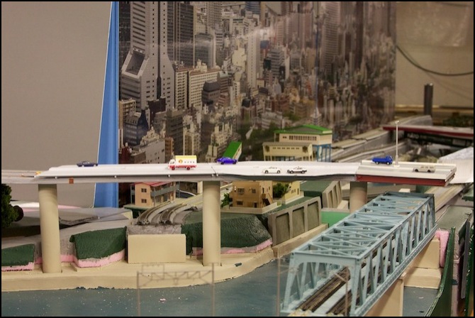
It’s also important in a more general scenic sense, as the combination of the river surface, the walkway along the river embankment, the road bridge, the park and street atop the embankment, the rail bridges, and the expressway above them, all create a “layered” look to that side of the river. And that’s an important aspect of city modeling, and in particular of Tōkyō; scenes don’t just consist of flat streets and tall buildings, but of layers with cuttings below street level and bridges above it. Cities are congested, and land is an expensive resource, and those two factors shape the use and appearance of the city’s spaces.
The eventual expressway will be made of plastic over a plywood spine for structural strength, and will be a continuous element semi-permanently mounted to the table it sits above. But for now, I wanted something that captured the look with minimal effort, to help me plan the other scenery and serve as a placeholder while I work on more important things (like carving the topography or getting the track working).
These and other photos of the highway are available in a larger size in the Highway photo album.
Structure
The highway consists of an upper deck (not yet built) of styrene laid atop a roadbed of plywood. The roadbed is attached with nuts and washers to 1/4” threaded steel rods, which in turn are attached to the table top using nuts and washers. Each support rod is surrounded by a length of 1” PVC tube held in place with washers on the rod. One support post has holes drilled in the washers and wood to allow wires to be fed through for powering LED lamp-posts on the highway.
The PVC tubing was sanded, then painted with a white plastic-friendly spray-paint to create a base coat, then painted with Woodland Scenics Concrete paint, which does a good job of representing sun-yellowed concrete. The plywood was eventually painted with the usual gray primer to seal it and eliminate the “wood” color from the underside. But first a groove was routed down the center from end to end to serve as a wire run for the lighting power supply wires (although in the end it was only used for the feed connector, and the actual power wiring was done with copper tape).
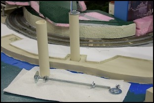
L: PVC Tube, Rod and Wiring, R: Plywood Support
Temporary Deck
As a placeholder, after I installed the support posts and plywood substructure I built a roadway out of gray foam-core and construction paper, with lane markings painted with a paint-pen.
The dimensions of roads in Tokyo are discussed on my Roads page. I went for a highway with two lanes in each direction of 3.25m width (a bit less than the 3.5m of the prototype) and no breakdown lane, although I did model an emergency pull-over area found on the original highway. There is a narrow (0.75m) edge on each side elsewhere (the final one will be closer to 1m), and a similarly sized median. In the final highway, the median will be slightly raised with a metal barrier down the center. It will also have periodic lamp posts, expansion joints, and route marker signs. But for now I’m omitting those details.
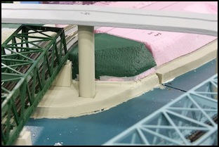
The temporary highway was constructed of three layers of foam-core attached to each other using double-sided permanent tape. This was built in segments about 12-18 inches long that fit where I wanted to put the supports. The initial supports are a simple box, also made with foam-core. And the sides of the foam-core on the upper section are hidden by taping a 1/2 inch wide strip of construction paper to the side, using the same tape (which turned out to be less than “permanent”, paper sections that were bent around curves came unstuck in a couple of weeks).
Expressway with foam-core temporary roadway
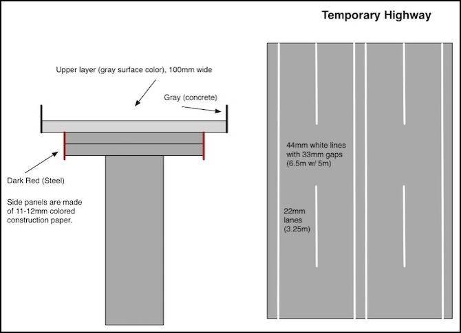
Temporary Roadway Design
I made the roadway surface by first drawing and cutting-out template shapes using posterboard (light cardboard), once I had all the angles and widths correct, I traced them onto the foam-core, and cut it with a razor-knife to match. Then I painted the lines using a steel rule and paint marker-pen. The deck was a sandwich of three layers of gray-faced foam-core, with 12 mm (half-inch) sides cut from construction paper.

Foam-core surface, cardboard template, and tools
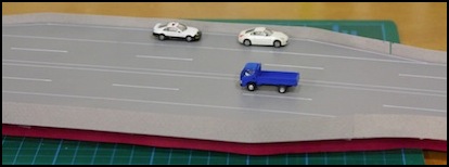
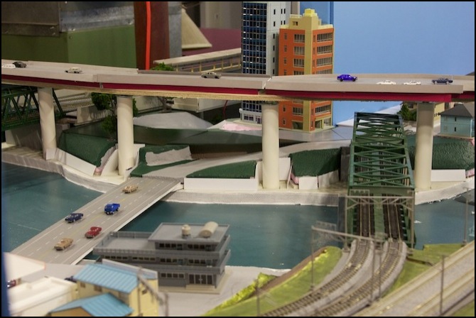
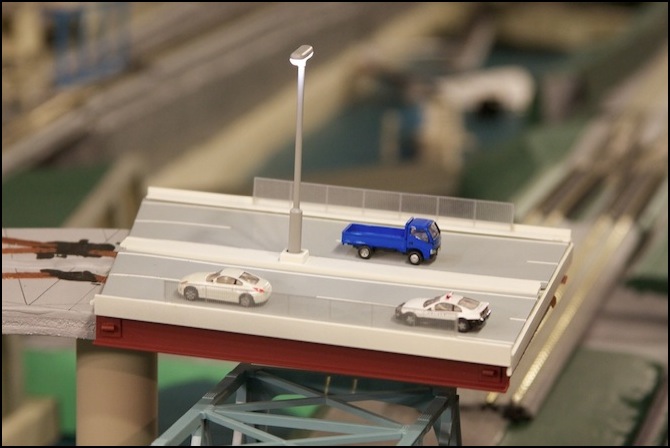
Finished temporary deck, with cars
Final Structure
The real upper deck is still in the design phase (and has been for some time, although I think I’m getting closer to starting construction). Measurements using Google Earth gave me dimensions for the prototype. Construction is documented on the page for the JNSForum 2011 Contest.
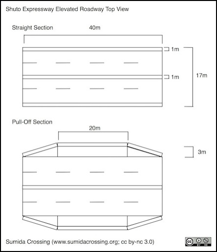
Prototype Dimensions (see Diagrams page for larger version)
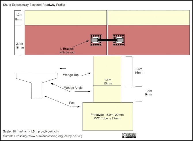
Planned Profile (subject to change)
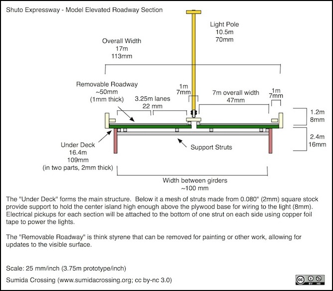
Planned Expressway Deck
The light fixture I’m using is an HO-scale Viessmann LED-based light with a socketed base (part 63641). These seem to be a little hard to find in the U.S., although I got mine off a clearance table at a local hobby store at a bargain price, so you can probably find them if you look. They throw a good circle of light, and spacing them about 8” (20cm) apart will probably look fairly good, as shown below.
First section “prototype” (I may re-do this when I build the rest)
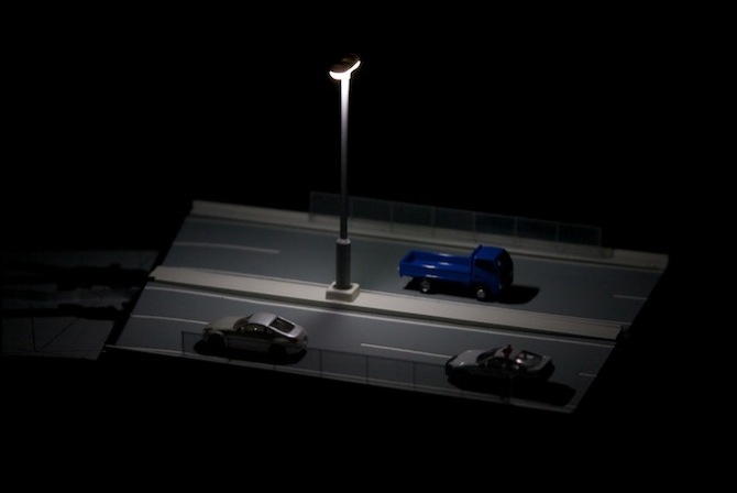
Testing the light for “nighttime” use
The next two sections have begun to take shape, but more slowly than expected.
