


DC Train Control
Early model trains powered by direct current (DC) used a rheostat to control the voltage, and hence the train’s speed. This worked, but it was far from perfect. In particular, DC motors don’t work very well at low speeds due to their design, and this simple approach did nothing to correct for that problem. Additionally, modelers wanted more features (like simulated momentum). And as DC motors evolved to draw less current, rheostats themselves became less effective.
Starting in the 1960’s throttles using more sophisticated circuity based on the newly-available transistor became more commonplace. These didn’t eliminate rheostat controls; you could still buy high-quality power packs using rheostats up to the early 1980’s at least. But the writing was on the wall. Over the next thirty years transistor throttles evolved as the technology evolved, maintaining a basic set of functions but achieving them in new, and generally better ways.
With the introduction of Digital control (c. 1989 if you count from Lenz’s design, although there were precursors) a new era started, which put the motor control circuitry on the train itself, using much more complex circuitry. Digital systems also allowed for more sophisticated control features, including constant-speed controls (rather than constant voltage) and user-configurable speed profiles (to replicate the different gearing of switchers and road locomotives, for example). And similarly a “DC” power pack could also use digital circuitry, although even today this isn’t common, and transistor throttles (in their modern form) still dominate DC Power Pack designs.
Parallel to the development of DC throttles there were a whole series of other throttles designed to work with modified locomotives to allow for more sophisticated control, which ultimately led to the development of DCC. I’m not going to cover those (see the DCC History link in the references section if you’re curious), but instead will focus on systems designed to operate one unmodified locomotive (or one set of locomotives working together) in an electrical block.
In the Beginning
The earliest model trains were not self-propelled, but like modern children’s toy trains, merely pushed by hand. Some more serious hobbyists used actual model steam engines to propel their trains. The first electrical model train was developed in the 1890’s by Thomas Marklin, a German toymaker. Maybe; there are several other claimants from about the same time, and it’s quite possible several developed them independently. In 1901 Lionel sold its first electric model train in the U.S. (the owner of the company, Joshua Lionel Cowen reportedly motorized his first train in 1884, at age seven). The train was powered by a battery.
Some early electric model trains used AC (alternating current) wall power on the rails (more than a little dangerous, even for adults!). But more common was the use of DC automobile batteries wired to the rails. Originally these were six-volt batteries, but as cars switched to use 12V systems, the trains did too. Early models used a rheostat, a variable resistor, to reduce the output from the battery to provide for lower speeds, since the speed of a DC motor is proportional to the voltage applied to it.
This basic approach continued into the days when relatively inexpensive rectifiers allowed power to be converted from AC wall current to lower-voltage DC, and rheostat throttles were still being produced up to at least c. 1980. However, with the development of the transistor in the 1950’s, throttles began to become more sophisticated. Transistorized throttles began appearing for sale in 1958 issues of Model Railroader magazine, and in November 1960, Jim Haning published the first article outlining the design of a transistor throttle a hobbyist could build.
Starting in 1961 editor (and transistor enthusiast) Linn Westcott began publishing a series of articles on the application of transistors to throttles, including a number of circuit designs, culminating in the February 1962 article describing his True Action Throttle II, a transistor throttle with pulsed power for low speed, and realistic momentum and multi-position brake controls. Much work by Westcott and others followed over the 1960’s and 1970’s, as more was learned about operating trains with specialized throttle designs, and as transistors and other semiconductors became less expensive and more robust.
Some Electrical Basics for Throttles
DC motors used in modern model trains are typically Brushed DC Permanent Magnet motors, at least in the typical indoor scales of N, HO and O, although other types may be used in some models. Such motors tend to be designed to run at fairly high speeds: 14,000 RPM at the rated maximum voltage is typical. Such motors also demonstrate approximately “linear” behavior as the voltage is lowered from that maximum: a 12V, 14,000 RPM motor driven with 6V will run at about 7,000 RPM. Reduction gears between the motor and the driving wheels convert this high rotational speed to a much lower rotational speed at the wheels.
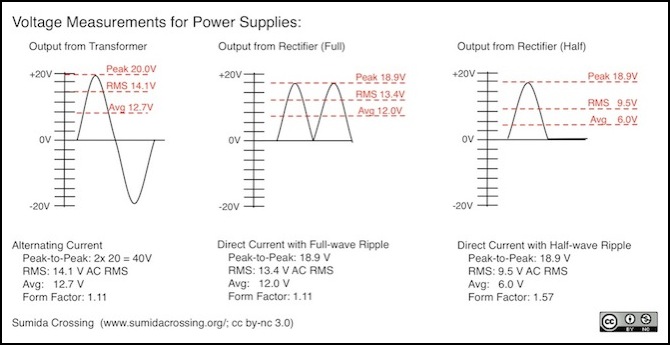
AC voltage, the kind that comes out of a wall socket, is typically measured as a “RMS” (root mean square) voltage. In the U.S., wall power is nominally 120 V RMS AC, although in practice it can vary from about 110V to 130V AC RMS. AC waves will have peak voltages greater than this RMS level, in both positive and negative directions. For example, 120 V AC RMS has peaks of about 169.7 volts (+ and -). A transformer that converts 120V AC to 14.1V AC RMS is producing an output with peaks at about 20 volts AC RMS.
What really matters to a DC motor though is the “average” voltage, not the RMS. There’s a relationship of RMS to average voltage called the “Form Factor”. This is essentially a measure of how “spiky” the power is. Higher peaks (and thus RMS) relative to average makes for a higher ratio. And the form factor depends on the shape of the power. Two common ways to shape power are to rectify the AC (convert it to DC) without filtering, which produces full-wave ripple DC, and to rectify half the wave (and discard the other half) without filtering, which produces half-wave ripple. Both of these have been used in pulsed-power throttles.
For a sine wave (wall current), the Form Factor is 1.11, and this carries over into full-wave rectified power (the shape is the same, it’s just been folded up to be always positive). But a rectifier typically loses a small amount of voltage, and a loss of 1.1 volts is fairly common, so our rectified power now has peaks of 18.8 Volts.
The form factor is merely a ratio of RMS to average voltage, so we can use it to convert between the two. In 13.4 V RMS AC (the RMS of voltage with a peak of 18.9), this gives us 13.4 / 1.11 = 12.0V.
But half-wave rectified voltage has half the average voltage of full-wave, which shouldn’t be a surprise since we threw half the wave away. But note that we have to use a different Form Factor here. Because it is more “spiky”, it has a higher form factor, of 1.57.
Note: various documents quote different form factors for Full and Half-wave (1.4 and 1.9 respectively), but these are what you get from the commonly documented formulas, so I’m not sure where the other numbers come from. In any case the result is the same: half-wave has a higher form-factor than full-wave.
This can get more complex when outputs aren’t in pure DC or pure sine wave AC. And different meters will report things using different scales, so it can be hard to tell if what you are seeing is RMS, average, or some other number. For simplicity, I’m going to try to describe things in RMS (for AC) and average (for DC and related waveforms). Note that this won’t always agree with what you’d see on a meter, or what my oscilloscope is reporting.
Most motor manufacturers recommend that the form factor not exceed that of full-wave rectified unfiltered DC. Use of higher form factors leads to increased brush wear and motor heating. This was a problem with early DC power packs that used half-wave rectified power as “pulsed” power (my old MRC 501 Throttlepack, for example).
Pulsed Power
Starting a DC motor from a stopped position is difficult, particularly when that motor is in a model train, connected to a reduction gear system and pulling a load of cars. Static friction (in the motor, geartrain and wheels of the pulled cars) is higher than the kinetic friction of a moving system, which means that it takes more power to start it than to keep it moving. Thus when you start a train with simple DC it goes from zero scale mph to some relatively large number.
Rather than using a “flat” DC voltage, one way to overcome this is to shape the power such that it takes the form of a series of pulses. A pulse has a higher peak power than average, which means that it has a higher peak torque than average torque. That peak torque kicks the train into motion against static friction, but the average torque keeps it moving against kinetic friction. Thus the right choice of pulse will let a train run at a lower speed than it would on simple DC. For example, full-wave ripple has a peak-to-average ratio of about 1.6:1, so there’s 60% extra kick to overcome static friction. As mentioned earlier, Linn Westcott found that for typical 1962 motors, a pulse frequency of about 40 Hz was optimal, but that this produced excessive heating when “square” pulses were used.
Pulsed power is useful, so a lot of effort has been expended to find out the best way to do it. Early on it was noticed that square pulses could produce effects that were detrimental to the motor, such as arcing between the brushes and the commutator, caused when voltage abruptly changed. This was more likely to be a problem with the sprung-metal brushes used in the larger motors common in the early 1960s, than it is with modern motors having soft-carbon brushes that conform to the shape of the armature shaft. One way arcing was addressed in early designs was to more gently shift from low to high voltages, ramping up to the peak over some interval. One common way to do this was to use the sine wave shape of ripple to provide the pulses.
But arcing wasn’t the only problem with pulsed power. In a normal motor, the magnetic field in each winding is created twice per rotation. At a typical low speed of 5 scale mph, a model will be moving about 15 mm/second (a bit more than 1/2 inch). That’s about one rotation of a wheel, or about 12 rotations of the motor (numbers all derived from one of my N-scale locomotives). So normally a motor winding will switch on and create a new magnetic field about 24 times a second at the slowest speed, and perhaps ten times as often at normal running speed. Westcott’s optimum frequency would switch power on 40 times per second per winding (less some time when the winding is off).
The windings that are energized are effectively turning on for each pulse, and that is happening quite often. With typical “ripple” based supplies, the frequency is 120 times per second, and if something like a 1 kHz pulse frequency were used this would mean 1,000 “on” cycles per second. Each time the pulse is turned on, some power is lost to creating the magnetic field, and when the pulse is turned off, the magnetic field decays and that power is converted to heat.
A motor that’s spinning can shed some it its heat due to air circulation (although this can be limited inside the case of a model), and at very low speed there’s less of this than at higher speeds, so this too contributes to heating.
Note: even older rheostat-based systems could use ripple as a form of pulsed power, and some did. As shown above, my c. 1972 MRC 501 power pack produces full-wave ripple normally, with a switch to set it to half-wave ripple (for a higher peak-to-average ratio at a lower frequency).
One way to address the problem of heating due to collapsing magnetic fields is to raise the frequency until the magnetic field doesn’t have enough time to decay before the next pulse comes along. This doesn’t completely eliminate losses, but it substantially reduces them. Some will still be lost in the gaps between pulses, but if the magnetic field stays at near-full power there will be much less heating than at lower frequencies. The exact frequency where this occurs varies by motor design, but for a modern N-scale motor it’s around 12 kHz. Thus pulses at the typical “supersonic” DCC decoder level of 15 kHz or higher will have relatively little loss due to heating.
But few transistor throttles operate at such high frequencies. Most, in fact, use the AC line voltage as their basis, and produce pulses at 120 Hz frequency. On a slowly turning motor this will produce some extra heat, but less than the motor would produce at full speed, which would be about 240 field changes per winding per second on normal DC. So line-voltage ripple-based pulses are relatively kind to the motor compared to medium-frequency (non-“supersonic”) pulses.
Pulses are still only needed at relatively low speeds, so removing them at higher throttle settings is a good idea. This is complicated by the fact that voltage doesn’t directly control speed. A train with a heavy load of cars will need more voltage to get it moving at a low speed than a lightly-loaded train. This means that power systems either need to sense load (which is complicated) or need to leave the pulses in place at higher voltages to be sure of working for heavily-loaded trains.
And one way to do that is to superimpose the pulses on a DC voltage. As the throttle is turned up, the DC is increased but the pulses are left the same, added on top of the DC. There are a number of other ways to do similar things, and at one time or another they’ve probably all been used in one throttle design or another.
So the bottom line on pulses is that they help low speed running and they aren’t needed at higher speeds, but most throttles aren’t very good at telling low-speed from high-speed. And done wrong, they can harm a motor.
Early Transistor History
Model Railroaders trace the history of transistor-based throttles to two articles by Linn Westcott in the February 1962 issue of Model Railroader one about the design of common motors and how they operated on DC and a second, “Seven circuits for transistor throttles” , providing some suggestions for how to improve their behavior. Westcott (1913 - 1980) was the editor of MR from 1961 to 1977 and active in many aspects of the hobby, but his work on motors and throttles helped redefine how modelers controlled their trains, influencing the design of these systems down to the current day. DC permanent-magnet motors don’t run well at low speeds, and much of his work was aimed at overcoming this limitation through clever design of the control system. His original designs used 40 Hz square-wave pulses, as he’d found these produced the best low-speed running. Later investigations showed that these could produce excessive wear on motor commutators as well as excessive heating in the motor coils, and throttle designs evolved some more to minimize these problems.
Westcott’s ideas were elaborated over the next twenty or so years into a series of designs for a succession of “True Action Throttle” (TAT) circuits, as well as inspiring many others to design their own throttles. While these original designs are now obsolete, surpassed by better ones, what we have today would not exist without them.
Note: the TAT name lived on into at least the 1990’s, but the later throttles were very different in design from the early ones. Westcott’s TAT-IV was his last design, and was fairly widely used (you could get them in kit form from Heathkit in fact).
The Rheostat Throttle
A simple Rheostat throttle provides a DC voltage that can be varied from zero to some maximum, and which can have its polarity reversed. The power supply could be a battery, or AC wall current converted to low-voltage DC (as in the diagram below). Although the use of rheostat-based throttles is now obsolete, many of the other features of this kind of throttle still exist in modern throttle designs, so it’s worth covering them in some detail, as a foundation for later descriptions.
Note: rheostat controls are sometimes described as “transformer” controls, although that’s not very accurate and any power supply running model trains off wall-outlet current will include some kind of transformer.
The diagram shows the basic components of a plug-in rheostat throttle. A transformer converts wall current from 120 Volts (or whatever your locality uses) to a lower AC voltage that depends on the intent of the power pack designer. A fuse protects the system against short circuits (this could also be a circuit breaker or self-resetting protective device). A diode bridge, also known as a rectifier, converts the low-voltage AC to DC. These come in both full-wave (four diodes) and half-wave (two diodes) designs, and some cheaper systems used the half-wave approach, which provides less power to the train, but otherwise works acceptably. Most power packs also have an accessory output, and if this is AC (and it often is), then it’s simply connected to the output of the transformer (but protected by the fuse) as shown here.
The fuse or circuit breaker is the fundamental limit on the current. If it trips at 2 Amps, the power pack can’t supply more than two amps to a train (and it will probably be rated as supplying less, as some circuit breakers trip at lower voltages than others, regardless of the rating. A pack with 2A protection might be rated as a “1.5A” power pack (which won’t stop it from delivering 2 A if the protection doesn’t trip). Note that all components have to be rated assuming at least the current that the protection can let through, and good designs will overrate them a bit just to be safe.
Note: in this diagram, as in all of my diagrams, a dot where two wires cross indicates a connection, whereas two wires crossing without a dot are not connected to each other.
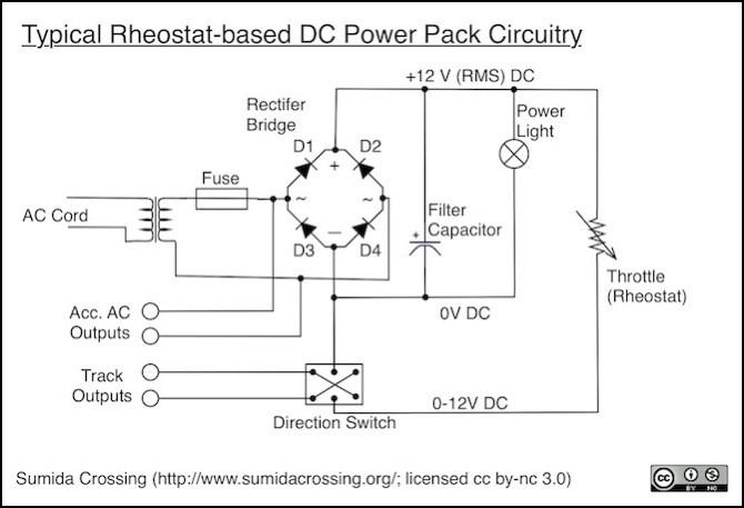
The output of the rectifier is voltage converted to DC, meaning that it has a potential between the output terminals that varies from 0 Volts to some peak voltage, with an average voltage (in this example) of 12 volts. However the rising and falling shape of the AC supply is still present, so the peak voltage is actually above the average voltage. This kind of varying DC is called “Ripple” or “Rippled DC”. Some power packs might use this directly, since it has the benefit that peak voltage exceeds average (as described on the DC Train Motors page, that helps with low-speed running).
The rectifier could be a single package with four leads, but more commonly it is four high-power diodes arranged in a square. Either way there are two inputs (for the AC from the transformer) and two outputs (providing DC ripple). The two outputs have a positive side (between D1 and D2 here) and a negative side (between D3 and D4). There’s no independent ground shown here (and that’s typical of model train power), so voltage will always be described as relative to the negative side of the rectifier. Thus that negative terminal becomes our “0V DC” reference.
To smooth out the ripple, it’s typical to place a filter capacitor between the positive and negative sides. As noted, some systems omit this. It’s also common to put a light on the supply, to show that it’s plugged in. There are several places this could be located, but between the positive and negative DC sides of the rectifier, as shown here, is typical.
It takes a very big capacitor to completely eliminate ripple, and for practical purposes that isn’t really necessary, so smaller capacitors may be used that partially smooth the output.
The throttle itself is a rheostat, which is a variable resistor. Set to one extreme, it lets full voltage (12V here) through, set to the other it lets zero. Normally these will be “linear”, so set halfway it would let half voltage (6V) through. This creates our track voltage level to run the train’s motor.
Finally, a simple dual-pole, dual-throw (DPDT) switch is used to flip the polarity on the track (from “right rail positive” to make a train go forwards to “right rail negative” for reverse).
Why We No Longer Use Rheostats
So what’s wrong with this? Well first, rheostats are very inefficient, and quite a bit of power is dissipated in the rheostat (converted to heat) it it isn’t at full throttle.
More importantly, a rheostat is a variable resistor. It’s ability to change voltage depends on current. So if you put on an older motor with a 1 Amp current, you’d only need a 16 ohm resistor to drop all voltage from a 16 volt source. So at full throttle resistance is zero, and stopped resistance is 16 ohms. But if you put a modern train with a 100 mA (0.1 Amp) motor on, you’d need 160 ohms. What this means is that you can only reduce the voltage by about 1.6 volts with a 16 ohm rheostat, and the slowest you can make that train run is nearly full speed.
Now typical currents were lower than one amp, and real rheostats had larger resistances, but not large enough for modern motors. And if you made them large enough, then they wouldn’t work very well for larger motors, as you’d need to turn the throttle nearly up to full before the train stated to move. Since different models have more of less efficient motors, no two models would run anything alike with the same rheostat. As motors became more efficient, and currents went down, rheostat power control really became unusable.
Another problem with the design shown here is due to the smoothing capacitor: as noted there’s typically no “pulsing”, so you don’t get better low-speed running. However the constant-voltage DC is actually better for the motors, so that’s something of a mixed result. You can make a rheostat throttle without the capacitor and get a primitive form of pulsing using the “ripple” from the original 60Hz AC, and while less than ideal for higher speeds, this will improve low-speed running.
Rheostat Throttle Example
For a real-world example, here are the full-wave and half-wave outputs of my old MRC 501, which is a rheostat-based design. These are measurements of a real running locomotive, which is why there’s so much noise (that’s arcing on the brushes and/or wheels as the train races around my test track at a couple-hundred scale mph).
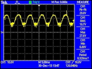
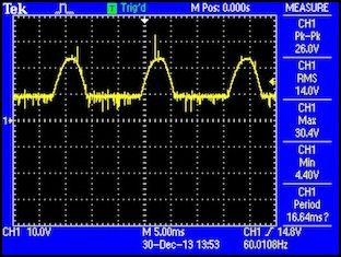
Full-wave (left) and half-wave (right) MRC 501 outputs at 100% throttle in “normal” (left) and “pulse” (right) modes
Note: the RMS values reported by the oscilloscope are likely somewhat confused by the noisy signal and the ~10V DC current being maintained between pulses due to the Back-EMF of the motor. Actual RMS voltage is about 17 volts for the full-wave output, which is a bit high for HO, but acceptable. It’s more than I’d want to use for N-scale, however.
This half-wave pulsing has another problem: it has half the average power of full-wave pulsing. So you can’t start the train on half-wave, get up to speed, and throw the switch to full-wave. Because when you do, the train will suddenly try to go considerably faster.
Overcurrent Protection
In any power supply, there needs to be a way to protect against short circuits. In a short circuit, resistance is very low, so current will be very high. This can damage the power supply, or what the supply is connected to (our expensive model trains), or it could even melt wires and start a fire. For that reason, any DC power pack will have some form of overcurrent protection.
The simplest method is a fuse. The problem with fuses is that they self-destruct to protect the circuit. Given how often short circuits occur with model railroading, replacing them could get expensive.
A better approach is a circuit breaker. When a short happens, the circuit breaker will trip, but it can be reset by the operator by pushing in a button or moving a lever. These are used on some DC power packs (Kato, for example; there’s a red button on the back that pops out in a short).
Finally, there are self-resetting protective devices. These are heat based, and trip due to the heat caused by a short circuit. It takes them a little while to cool down, then they’ll turn the power back on. If the short still exists, they’ll repeat the cycle. These are handy because the operator doesn’t need to do anything (except fix whatever caused the short). And they’ve been in use just about forever: my c. 1972 MRC 501 has one.
All of these systems have a maximum current rating, and that places an upper limit on the power used by the trains or the damage that can be done by a short. Actually some power will be lost in the circuitry, and protective devices may trip at values slightly below their rating, so this is only approximate and the pack should be rated at a lower level than the protective circuit. And note that typically the same device protects both the train and the accessories, so using more power for accessories means less will be available to run the train (which isn’t likely to be a problem unless you have a lot of accessories).
Ideally you want to have the lowest “maximum current” consistent with the needs of your equipment. But don’t cut it too close; add at least 20% to what you think is your maximum to handle losses, and 50% might be better to allow for component aging and unexpected demands. Just don’t go buying 20VA when you need 10VA. It’s not that it won’t work, but if anything goes wrong there’s more room for damage to your train.
Power Ratings
A DC Power Pack will have several ratings. Maximum track voltage is an important one. This is typically around 16 - 18 volts for HO, and 12 - 14 volts for “N”. These are often very approximate, and a “16 Volt” pack could easily output 19 volts. They’re also hard to measure, as a simple DC multimeter will read peak power, not average, so readings can be misleading with any kind of ripple or pulsed power. And “RMS” meters don’t generally do a good job calculating RMS for DC with oddly-shaped waveforms, so these can be misleading too. An RRampMeter is probably the most useful way to measure power pack output voltage, and it will also measure current being used, which can help you determine if you have enough power in your supply.
More isn’t necessarily better with DC motors, as they’re designed to run on specific maximum voltages. But people often run N-scale (nominally 12 volt) trains on 16 or 19 Volt HO power packs, so clearly most train motors are not exactly limited to those normal voltages. Still, buying the right voltage for your scale is a good idea.
Note: if you buy imported N-Scale Japanese models, keep in mind that some of those really are designed for 12V (or sometimes less!), and there’s more risk in running them at HO voltages. This is reportedly an issue with at least some light-rail “tram” models. Older models with bulb lighting can also have problems at higher voltages (mostly an issue for DCC conversion). Most recent Japanese models seem to be okay with higher voltages though.
Another rating is the power in “VA” (another word for this is “Watts”, but it isn’t as often used in model railroading). VA is important because it relates to maximum current. Maximum current will be limited by the fuse, but may be limited by other aspects of the power supply design. The rated maximum current, if it isn’t stated separately, can be found by dividing VA by maximum track voltage. So, for example, a 20 VA, 16 volt power pack can provide up to 20 / 16 = 1.25 Amps of current to a train’s motor. How much power is needed depends on the motor design, but being able to provide the full “stall current” of a motor, plus additional current for any lights, is desirable. See the Power Requirements page for more on this.
The Transistor Throttle
Transistor throttles have been around for about fifty years now. In that time there have been many very different designs, and many lessons have been learned about how to design such throttles. I’m not even going to try to provide a complete survey of these, but I’ll note some of the most important designs and lessons learned.
Basic Transistor Design
At heart, a transistor-based throttle is using one or more transistors as a power amplifier, taking a small variable-voltage control signal and using it to switch on increasing amounts of track power. The beauty of this is that it’s easy to modify that control signal to produce various effects. Needless to say, circuits can get much more complicated than the one shown here.
With transistor designs, usually a potentiometer will be used as the throttle knob. Unlike a rheostat, with a potentiometer the current through it is fixed, and a part of the throttle design. And that means the voltage drop across it is always the same for a given throttle setting, regardless of what it’s being used to power. A center tap moves as the knob is turned, allowing a variable voltage (from zero to some maximum, here a maximum based on the 14 V ripple) to be taken out and create a current sent to the amplifier. Kato’s current power pack is a good example of this, as seen in the following diagram.
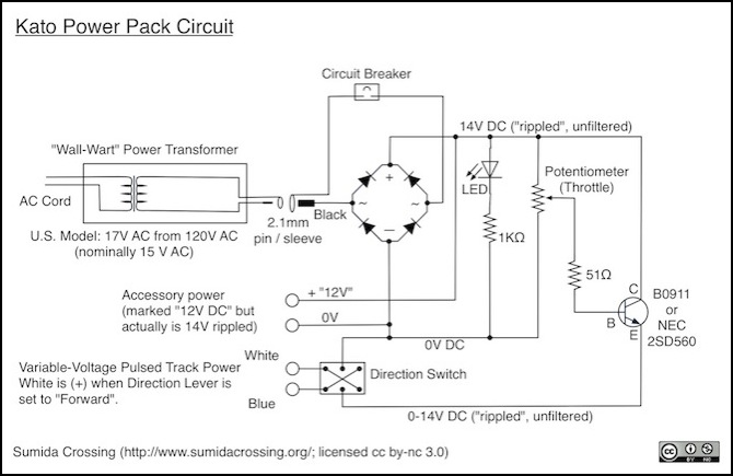
This pack lacks the filter capacitor shown in the Rheostat diagram above, so what’s going to the track will be based on “ripple”, not flat DC. Kato also replaced the bulb power light with an LED, which wastes less power and isn’t likely to burn out. Additionally, the accessory output taps off the DC side of the rectifier, so DC (actually “ripple”) is provided for accessory use.
But otherwise, it’s basically the same design, with a potentiometer and transistor replacing the rheostat. Full power (ripple) is fed to the “collector” side of the transistor (C), a current controlled by the potentiometer setting and the 51 ohm resistor is fed to the “base” (B) of the transistor, and this controls how much of the voltage present at the collector is allowed to flow to the “emitter” (E) side of the transistor. From there, it flows to the track as in the earlier design.
There’s nothing fancy here. No momentum or braking. There’s no adjustment of the pulses either: what reaches the track is ripple that’s been scaled to some maximum voltage controlled by the throttle, but even at full throttle it’s still ripple.
Note: although it looks like the ripple is super-imposed on a DC voltage in the two oscilloscope traces below, that’s actually an effect of the Back-EMF created by the magnetic field in the motor, which is going to keep some current flowing even when the power supply voltage is off. As before, these are measurements of a real running locomotive, so there’s a lot of noise at high speeds. There’s much less when the motor is turning at a small fraction of top speed.

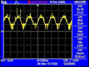
Kato track power output at 30% (3.7V RMS) and 100% (15.8V RMS, although that’s probably an error by my scope due to the noise)
Note that the full-voltage output here is essentially identical to the full-voltage full-wave output of my MRC 501 pack illustrated further up the page, despite there being about thirty years between their designs and two very different control circuits. Simple ripple-based track voltage remains a good way to power trains. Not the best perhaps, but still a significant improvement over simple DC.
Ideally, waves with these peaks would have RMS values of 4.0 volts and 14.9 volts, so I think this scope is being confused when it calculates the RMS of both, but much more so by the noisy signal at full throttle.
With this kind of throttle, the selection of potentiometer, scaling resistor and transistor are somewhat interrelated, as you have to produce a current to the base that, given the “gain” of the transistor, will allow full voltage through when the potentiometer is set to maximum throttle. In the early days transistors had poor gain, and a “Darlington” pair of transistors were used to compensate for low gain. Today, a single modern power transistor (which may internally still be a Darlington pair) can be used.
Momentum and Braking
One commonly-desired feature of throttles is some form of simulated momentum. Real trains take miles to stop from full speed, even with normal braking, and can coast ever further. Models tend to stop immediately if you cut the power. The idea of momentum in throttles was for some method to gradually change the output power to rise (or fall) to meet the level set by the throttle, rather than having the throttle directly control the output voltage.
One common method to implement momentum was to simply connect a capacitor to the output of the potentiometer, so that when the throttle was turned off the transistor would be kept on, at a gradually reduced level, until the capacitor drained. The rate could be fixed with a resistor, or adjustable with a small rheostat or potentiometer.
Braking was similar to momentum, in that it needed to gradually reduce track voltage when the brake was applied, and restore it when released, even if the throttle remained unchanged. There are a number of ways to do this, but again it’s mostly about altering the input to the power amplifier. A good feature to have with such systems was an “emergency brake”, which could act quickly (with less or no momentum) to bring the train to a halt.
[more to be added here about transistor throttles and their evolution]
References and Further Reading
Applying PMDC Motors (PDF), by Ronald Bullock, Power Transmission Design, May 1995.
DC Motors: Coercing Top Performance with AC Drive Signals, by Bruce Metcalf
This is a very thorough article on the different kinds of power than can be used to drive a DC permanent magnet motor for model railroading, and the effects of them.
DC Throttles page, Armadillo & Western website by Fred Horne (reportedly; he doesn’t seem to actually list his name on the site)
This site has pages describing several kinds of modern DC throttles.
DCC History, from the DCC Wiki
Although this is about the evolution of DCC, it may be of interest as a chronicle of historical developments.
High-Performance Throttle, by Rich Weyand, with Bill Pistello & Bill Reid (TracTronics)
This article, previously printed in the February 1995 issue of Mainline Modeler, describes a transistor throttle optimized for low-speed use with minimal motor heating.
Model Train History, by Barry Coulter
Various Transistor Throttles, by R. Paisley
This page includes designs for a number of relatively modern transistor throttles, with additional discussion on topics including use of pulsed power and current limiting.
