


Mobile DCC Decoders
The decoder is the part of the DCC system that receives commands, and controls some other circuit or device based on those commands. The most common kind is the decoder in a locomotive or car (called a “mobile decoder” for obvious reasons), which controls the DC motor of the locomotive, and usually also controls headlights, taillights, and other lighting. There are also mobile decodes that do not control the motor, but only provide accessory outputs to control lights in response to throttle direction or function-key settings (typically called “accessory decoders” or “function decoders” to separate them from full-featured mobile decoders, but they are still essentially mobile decoders). But there are also “stationary decoders” that control fixed equipment such as turnout switches, signals, or crossing gates. This page is going to focus on the kind of decoders mounted in trains, and describe some of the important attributes of these. There is a focus on Digitrax’s line of decoders, as that’s what I’m presently using, but I’ll include comments on some other common decoders used for N-scale.
Note: this is not a survey of all decoders, and in particular I’m focused on the ones applicable to my model railroad, which does not include any of the simpler decoders sold with some train models. I’m using more feature-rich decoders, and many of the things discussed here aren’t present on basic decoders.
Sizing Decoders
Many locomotives have decoders designed for them, which replace their existing lightboards. That’s the simplest case. But in many instances there will be a socket, in one of several standard forms, and any decoder matching the socket can be plugged in. And on older trains, and unfortunately on most of the Japanese-prototype trains I run, there is no provision for a decoder, and one needs to be wired in. This involves soldering, but first it involves selecting an appropriate decoder.
Three things need to be taken into account: will it fit inside the locomotive (or can it be made to fit), does it have enough outputs for the lights it needs to control, and does it have a high enough power rating to avoid burning out?
Answering that last question requires knowing the stall current of the locomotive’s motor, which is how much power the motor draws when it is unable to turn. This is also the maximum amount the motor can draw, and thus a decoder large enough for a motor’s stall current will never be overloaded. My DC Power Requirements page describes how to measure stall current, although in practice you don’t need to do this as long as you are careful to select a large decoder.
Note: some older trains use significantly more current than modern ones, and can be problematic. For those, testing for stall current is a good idea.
Stall current is important because it’s the maximum the motor can draw (well, sort of), and if the locomotive gets stuck against an obstacle (such as something placed on the track and forgotten) it could be drawn for an extended period and damage a decoder that wasn’t built for that load. A motor may also draw something close to stall current momentarily when starting from a stationary position, or reversing if it is already in motion.
So when selecting a decoder, it needs to be rated for something greater than the maximum possible stall current of the motor it will control. For N-scale, a 0.5 Amp (500 mA) decoder should be safe as most modern N-scale trains have a stall current below that, but some older trains may exceed this; if in doubt, use a decoder rated for 1 Amp or more.
The accessory (or function) outputs of the decoder also needs to be considered. Most LEDs draw only 20 mA, 30 mA at most (and often less). Bulb lighting can draw more like 60-75 mA per bulb. Most decoders are rated for at least 125 mA per accessory output, which means they can probably drive two headlight bulbs off one output. But if the rating was 100mA, or if two headlights and taillights using bulbs were connected to a single output (as is sometimes the case), this could overload the decoder. So the decoder’s maximum current rating for the accessory outputs shouldn’t be ignored.
Note: the stall current isn’t actually the maximum current the motor can draw. The maximum occurs if a motor going full speed in one direction is suddenly reversed to going full speed in the other with no delay (i.e., when your five-year-old throws it into reverse). In that circumstance, the motor has a very brief spike that’s twice the stall current. However it’s a brief spike, and a decoder should be able to cope with it. Unlike the stalled condition, where a locomotive could remained stalled indefinitely and drawing the full stall current for several minutes or longer.
Standard Decoder Interfaces
Some decoders are designed to be wired into older locomotives, or are designed specifically to fit one locomotive or a family of similar locomotives from one manufacturer. But many are intended for use in newer “DCC compatible” locomotives, and for those some kind of standard interface is desired. For various reasons, one interface wasn’t sufficient, and the NMRA has recommended a total of seven to date.
The National Model Railroad Association (NMRA), in Recommended Practice RP 9.1.1 (PDF), Electrical Interface and Wire Color Code, originally defined small (in-line, 6-pin), medium (8 pins in two rows of four) and large (4 pins in a square block, offset) “recommended” sockets. The small is for N-scale, and defines outputs for just the motor, head and tail lights. The others are for larger scales, with the large having only motor outputs, and the medium supporting one additional output.
In Europe, the MOROP (“European Union of Model Railroad and Railroad Fans” in English) defines standards for model railroading under the “NEM” (“Norms of Model Railroading”) identifier (German, French). Their DCC standards are defined in conjunction with the NMRA. European manufacturers tend to identify the sockets by their NEM numbers: 651 for the “small” 6-pin, 652 for the “medium” 8-pin, and 654 for the “large” 4-pin sockets.
None of these connectors provide outputs for speakers, as their definition predated the circuitry required to create digital sound systems that would fit in a locomotive.
The six-pin (NEM651) socket has one issue: it only has pins for track (Red, Black), motor (Gray, Orange), Headlight (White) and Taillight (Yellow); there’s no “common” (Blue). The usual solution is to wire the lights to use one of the rails (it doesn’t matter which, but both need to use the same one) as the common. You get a bit less light this way, since the track is sometimes at the same polarity (and hence voltage is zero) due to the AC nature of DCC, but in most cases that’s probably not noticeable.
A NEM651 socket is a female circuit board header with 0.050” (1.27 mm) pitch between pins about 0.017” (0.406 mm) in diameter. Digikey S9008E-06-ND or S9010E-06-ND (right angle wires) will work as sockets for these, and S9014E-06-ND or S9016E-06-ND (right angle wires) as pins for a harness. You’d need to solder wires to them, and that can be very hard, but my preliminary testing shows that decoders will work with these. However, I did have trouble with one of my decoders (and only one) pushing one of the socket elements out (and only one of the sockets, the other five were fine). I suspect it was some kind of “just a bit too small” problem, or perhaps some solder ran down into that one when I was attaching wires. In any case, while it works, it’s not perfect.
In 2008, RP-9.1.1 was updated and now defines several additional connectors. A 21-pin decoder interface, identified as the 21MTC, is the recommended connector for new locomotives, and has outputs for the motor, a speaker, head and tail lights, four AUX outputs (AUX1 - AUX4) and “train bus” pins, as well as support for brushless DC motors (which need sensor inputs). This is based on a design created by Märklin and ESU, and widely used in Europe. Use of the older connectors is still considered conformant (meaning allowed), but use of the 21MTC is recommended.
As an alternative to this, the RP also defined a 8/16/22-pin decoder interface, known as the PluX8/PluX16/PluX22, developed by Digitrax and Fleischmann. This interface uses a subset of the pins in the same arrangement for decoders with less functionality. The 8-pin model has only motor, head and tail light outputs, the 16-pin model adds a speaker, two AUX outputs and the train bus, and the 22-pin model adds four more AUX outputs (AUX4 - AUX7). The Plu8/16/22 does not support brushless motors.
Note: Exactly what the “train bus” is for isn’t clear, and it doesn’t seem to be in use today. Presumably this is for some future standard for a serial bus to permit chaining auxiliary boards to the main decoder board, to add functions without having to define more pins and a larger connector.
For more about physical installation of wired decoders, see my Installing Decoders page.
Wired Decoders
Older trains that weren’t fitted with a socket require the decoder to be wired into the train. This involves some simple soldering (and yes, if you’ve never done that, it’s not “simple” at all the first time; learn on something other than an expensive model). This is really basic, and doesn’t require great skill or a knowledge of electrical engineering, just good eye-hand coordination, the right tools, and some basic knowledge and common sense.
Decoders have two wires to pick up power from the track (typically color-coded Red and Black), two wires to connect to the motor (typically Orange and Gray) and zero or more other wires for controlling lights and other accessories (typically Blue is a common for lights, and White is used for a forward headlight and rear tail lights, while Yellow is used for a rear headlight and forward tail lights).
Real locomotives always have one end designated the “front” (often in the U.S. an “F” is painted on the frame side near that end). When a DC-powered model train is placed on the rails with a positive voltage to the “right” rail (“right” when looking towards the front from the engineer’s seat), the locomotive should move forwards. That’s the basis for designating the Red wire as the “right” wire and the Orange wire as the “positive” motor wire. If you hook up the red wire to the right side pickup (and thus black to the left side), and the Orange wire to the motor contact that previously connected to the right side (and thus Gray to the left side contact of the motor), then when used on DC track the locomotive should move forwards. This also ensures that when the DCC throttle is set to “forward” the locomotive will move forwards (unless the decoder has been set to swap directions).
With DCC, what matters is just the Orange (and Gray) wire, as the rails carry an AC, not DC, signal. This is important as it makes the “forward” setting on DCC throttles that label the direction control actually mean “forward” motion of the locomotive.
If you get this wrong, CV29 can be used to reverse the “normal” direction of travel. However, when you do that, the White and Yellow wires (or directly connected LEDs or bulbs) would still be “on” at the wrong time. There’s no standard way to fix this, but most manufacturers have a proprietary CV that can be used (for Digitrax, see the description of Function Remapping using CV33 & CV34 below). If you use Advanced Consisting (set in the decoder, as opposed to Universal Consisting set on the command station) to run multiple locomotives together, there are additional CVs to set to control light direction, see the features description below.
In an EMU or DMU where the motor decoder is in a different car from the decoders controlling the lights, all of these need to agree on which end is the “front” and be wired to reflect that. In many cases this is completely arbitrary, as most such trains are front-to-back symmetric. In those cases, just pick one end (you can paint an “F” on the underside of the cars at one end, if you don’t want to forget how you wired it).
For more about wired decoders, and specifically about their use in multiple-unit trains with separate cab and motor cars, see my page on Wired Decoders.
Decoder Features
DCC decoders support a number of features. If a decoder supports these, they are typically enabled and adjusted by setting values in Configuration Variables (CVs), described below. Some of the more useful ones are:
Addressing and Extended Addressing
Simple decoder addresses are a number from 1-127, often limited to 1-99 in practice. Extended Addressing, also called “four-digit addressing” allows numbers from 1- 9983, although some manufactures will limit their decoders to a subset of these. All decoders default to using address 3 unless installed at the factory and given a documented address. If the command station doesn’t have a function to program extended addresses directly (or if it doesn’t work with some decoder), but can still operate train with such addresses, you can program extended addresses by directly writing to the address CVs on the programming track. I’ve written this up on my Kato Decoders page, and the Kato decoders support extended addressing, but can’t always be reliably set to extended addresses by the usual address setting mechanism of command stations.
Function Outputs
The most common use for a function output is to turn a light on or off. With sound-effect decoders these can also be used to trigger specific sounds, like bells, horns, air compressors, and coupler clanks. Head and tail light functions may be directional (e.g., FR(f), the forward headlight, only comes on when the train is moving in its “forward” direction, likewise FR(r), the rear headlight, only comes on when the train is in reverse; both may be wired to both white headlights on one end and red taillights on the other end, so that the train has the correct lights lit in either direction). There are some “standard” assignments for function outputs (e.g., F0 is the lights on/lights off function for head and tail lights), see your decoder’s documentation for the ones it supports.
Momentum
When a speed is selected, normally the locomotive starts moving at that speed immediately (or as quickly as a small model can accelerate to it, which is quite quick compared to the prototype). For more realistic operation, acceleration and deceleration rates may be set, to delay the time it takes for the train to speed up or slow down. This makes operation more prototypical, but can make it hard for less-experienced operators to avoid running into other trains. See the Speed Tables page for some additional discussion of this.
Speed Tables
The motor in a typical model can drive the train considerably faster than the prototype, particularly when it is lightly loaded. A speed table can be used to restrict the maximum speed to a more realistic one, and allow the operator to have finer control (more throttle movement) at low speeds for precision in coupling or stopping at stations, with a coarser control (less throttle movement for a greater change in speed) at higher speeds, where precision is less important. Not all decoder models provide for such adjustments, and some only provide the basic three-CV version. See the Speed Tables page for additional information.
Consisting
Each locomotive (or other motorized car) has a unique address. Consisting allows two or more locomotives to be controlled using a third address, so that “double-heading” (using two locomotives to pull a longer train) can be more accurately represented. For this to work well, the two trains must have their speeds synchronized at all throttle settings (which may require separate speed tables for each). Each locomotive can still be controlled independently using its own address also, although this may be disabled when the consist address is enabled to avoid accidents.
There are several kinds of consisting: Advanced Consisting uses an address set in the decoder (in CV19), while Universal Consisting uses the command station to associates one or more additional addresses to the address of a single locomotive. This requires no support or settings in the decoder (other than speed-matching so both run at the same speed for the same throttle setting). There’s also Basic Consisting, where one locomotive’s decoder temporarily has its address changed to be the same as the other.
With Advanced Consisting, CVs 21 and 22 typically need to be set to indicate which functions should respond to the consist address rather than the normal address when consisted (e.g., you leave sounds like coupler-clank on the normal address, so each can emit the sound separately, but you put engine speed sounds on the consist address so all will respond to the throttle setting).
Note: Advanced Consist addresses use the “two digit” form, so these are fairly limited and usually only assigned for the duration of a consist, rather than permanently.
Direction of Motion
Locomotives normally have a “front” (often identified in North America by a small “F” painted on the frame at that end). When the throttle is set for “forward”, the locomotive should move towards its front. But if two locomotives are to be consisted back-to-back, this won’t work. And sometimes you get the wires wrong and don’t want to re-solder them.
CV29 has a “reverse direction” bit, set this and the locomotive will run in the opposite direction of how it normally would. This is used to fix wiring errors, typically, although it could be used in consisting to allow tail-forward operation if CV19 isn’t available.
CV19 has a “reverse flag” which when set reverses the normal direction of motion, which is useful when coupling locomotives back-to-back. This works with the consist address, so it’s only available when doing Advanced Consisting, not Basic or Universal. To use this, add 128 (decimal, or 0x80 hex) to the consist address and store the result in CV19.
Back-EMF (BEMF)
This is a feature that attempts to keep the motor turning at a constant speed by sensing the current draw (current will increase when the motor has a greater load, and voltage must be raised to compensate). Back-EMF, configured properly, will result in smoother low-speed operation and better operation on a grade. Not all people like the effect on grades, as it’s viewed as “unprototypical” for trains not to slow down on a hill, so some decoders will allow you to turn Back-EMF off at higher speeds. Each manufacturer that implements Back-EMF has their own recommendations for tuning it on a given locomotive (see the BEMF page for more on this).
My take is the BEMF is indispensable. I won’t buy a decoder that doesn’t support it now that I’ve seen it in action.
Starting Voltage Etc.
In addition to speed tables and Back-EMF, there are often other capabilities in a decoder to provide an extra bit of voltage to get a stopped locomotive moving, or to ensure reliable low-speed operation. These come in a variety of forms depending on the decoder manufacturer. Most however follow the NMRA standard (defined in RP-9.2.2) of using CV2 to set the voltage used at speed step 1 (0 = 0% of maximum motor voltage, and 255 = 100%).
Torque Compensation or Dither
I’m still not entirely clear on what this is, but there’s a reasonable-sounding explanation on this website by someone who appears to know what he’s talking about. If that’s true, then this is something you don’t need if you use BEMF.
Decoder Lock
Some decoders support locking as defined in RP-9.2.2. If a decoder lock feature is supported, it is supposed to use CV15 and CV16 in the following manner:
First, you set CV16 to a number when installing a decoder in a train that has more than one decoder using the same address (e.g., when both a motor and sound decoder are used, rather than one that does both). This is very useful with multiple-unit trains, where the motor is separate from the cab car lights, but you want both to respond to the same address for directional control. The CV16 number is called the “ordinal” of the decoder, thus the first one in the train could be 1, and the second 2, or you could always use 1 for the motor, 2 for the sound, and 3 for cab #1 and 4 for cab #2. It’s just a number, but once you set it, you never change it.
Then, to program the decoder you write the same number into CV15. A decoder is unlocked with CV15 = CV16, so if, for example, you wrote “2” to CV15, then only in the sound decoder (which you earlier set to “2”) would the two match, in all the others CV15=2 and CV16= something else. That way, you can unlock one decoder and modify it, then set CV15 to some other number and it locks again.
When a decoder is locked, only CV15 can be written. Some manufacturers may also prevent reading CVs (it’s not required per the RP, but it’s handy since otherwise multiple decoders would try to respond to a “Read CVxx” request).
Note that a locked decoder can’t be reset, so if you forget what number you put in CV16, you need to try each and every number from 0 to 255 in CV15 until it unlocks (some manufacturers may limit the range of allowed numbers, and even if they don’t, you’re best off using low numbers in case you someday need to guess). Also note that the ordinal only matters if the decoders have the same address in Ops Mode (on the running track) or if the decoders are in the same car placed on the programming track. Decoders in two different trains using different addresses can both use “1” for their motor decoder without confusion.
TCS decoders unlock if you set CV15 to 0 regardless of the setting of CV16. That’s not “standard” and decoders from other manufacturers typically don’t work that way.
Supersonic
All decoders drive their motor outputs with pulsed “PWM” signals, which cause the motor to vibrate slightly. A “supersonic” decoder uses high-frequency PWM that is less prone to creating an audible buzz from the vibration. There’s a cost to this, as a motor driven with supersonic pulses will have less pulling power than one driven with lower-frequency pulses, and many (not all) supersonic decoders allow this feature to be turned off.
Transponding and RailComm
These are two competing features for providing feedback from the train to the command station (or to a computer or other device). Both require additional hardware beyond the decoder, some of it quite expensive, to be used. Transponding is Digitrax’s proprietary method, although it may be supported by some others. RailComm is a Lenz solution which is on track to be standardized by the NMRA (but which is still in draft status at this point, albeit a fairly solid-looking draft). A decoder can only do one or the other, but it appears that a layout could use both. I’m not aware of anyone who’s tried that though.
My own experience with Transponding was disappointing, but I haven’t tried RailComm at all. RailComm products are still rare, see my DCC Control Systems page for a little detail.
Lighting Controls
Most lighting controls aren’t relevant to Japanese trains unless the decoder is being used for specialized equipment. Modern Japanese trains don’t have Mars or Gyralight headlights (found on older U.S. locomotives for the most part). Some older trains however might have had these. Strobe lights might be found on specialized track maintenance equipment. Ditch lights are used on some Japanese trains, but I’m not aware of any N-scale model that has them. For the most part, Japanese trains just have headlights and taillights (and sometimes one taillight on the front is illuminated for specialized switching activities, but no N-scale model I’m aware of replicates that).
The one “effect” that is worth having is “Rule 17” lighting. The name comes from U.S. practice, but it’s common in Japan and Europe also. Modern high-intensity headlights used on trains are very, very bright, so the general rule is that trains passing another train, parked on a siding, or entering a station should dim their headlights. It’s also fairly common to dim them when working in a yard. So a decoder that supports a triggerable “Rule 17” effect (meaning you can press a function key to switch the light from bright to dim and back) is important. A decoder that dims the headlights only when stopped is less useful.
Decoder Programming
There are several different programming “modes” supported by DCC command stations. Most common is “direct mode” used on the programming track, and “ops mode” used on the actual layout track. Support for direct mode became a requirement in 2002, so some older systems may require the use of other modes. The programming track is also known as the “service mode” environment, to distinguish it from the “ops mode” environment on the layout track. But where the Ops Mode environment only supports Ops Mode programming, the Service Mode environment supports a number of different programming types. I’ll refer to the service mode environment as the “programming track” for clarity in distinguishing the environment from the programming modes.
Programming on the programming track is required to reset a decoder of unknown address, since programming commands on the layout track (Ops mode) require the use of the address.
The programming track uses a low-power signal to program the decoder. In some high-power decoders (like sound decoders) this may be inadequate, and a booster may be required. I’ve used the DCC Specialties PowerPax on my Zephyr for programming HO sound decoders in the past. A high-power decoder is supposed to cut-out high-power loads while on a programming track, so this won’t be necessary. Clearly, not all do.
Wires to a programming track should be kept short to minimize distortion in the signal. While it’s possible to use a section of layout track with both rails insulated as a programming track, connected via a DPDT A/B switch to both programming and layout track outputs on the command station, the length of wire between the command station and the track should be minimized, and the largest wire practical should be used to minimize resistance in the wire. That said, voltage drop should be minimal at the currents used, and there have been examples of people running a dozen feet or more to a programming track without problems.
Don’t forget to clean the programming track. Like any other track it can get dirty and make poor contact with the wheels.
Here’s a bit of black magic I’ve never had to use, but have read about. There are, apparently, problems sometimes in programming decoders because the length of wire to the programming track ends up creating a resonance. You can correct this if you have problems programming decoders by changing the length of the wires used.
Decoder CVs: Standard
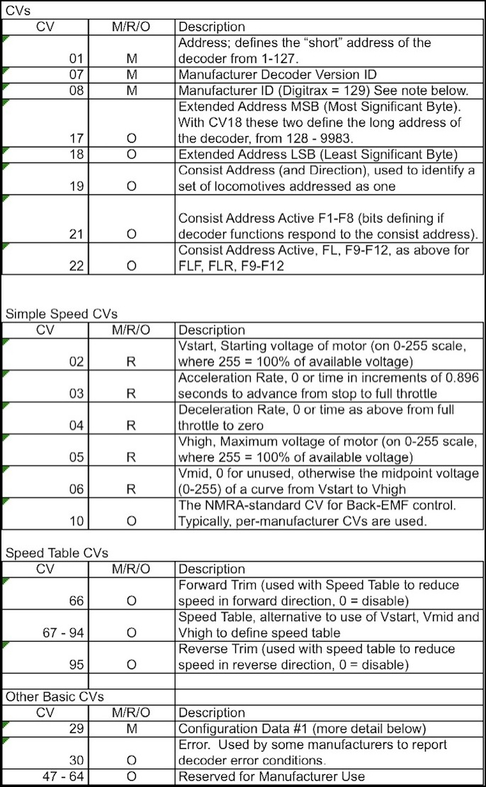
The NMRA, in Recommended Practice RP-9.2.2, Configuration Variables, defines a number of CVs as Mandatory, Recommended or Optional (note that since this is a “recommended” practice document, none of these are truly mandatory, but those are likely to be more common than optional ones). See the standard for the complete list, the following tables summarize the most important ones:
Note: “FL” = “forward light” or headlight. FLF = Forward Headlight, FLR = Reverse Headlight. Both head and tail-lights may be wired to one output, so FLF could control both the front headlights and the rear taillights.
Addressing CVs
Configuration variables are grouped into several sets for the standard ones, with additional per-manufacturer CVs also defined. The “M/R/O” column lists the NMRA status of each CV, whether it is Mandatory, Recommended, or Optional. Many of the Optional ones are in common use (extended addressing, for example, is nearly universal).
CV29
CV29 provides some basic configuration of which features a specific decoder uses. Not all decoders necessarily support all of these features, but if the feature exists and can be enabled or disabled these bits are used to do so (and all decoders should use these bits in the same way). Numbers in parentheses are the decimal equivalents of the bits, set a specific set of bits to 1 by adding their values, then setting the CV to the result (e.g., use of speed table 66-95 plus extended addressing would be enabled by setting CV29 to 16+32 = 48 if no other features were enabled).
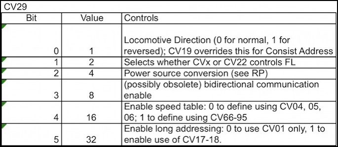
Bits in CV29 can be set by adding their values and writing the result to CV29. For example, to set bit 1 (CV22 controls headlight) and bit 2 (power source conversion), the two values (2 and 4) are added, and “6” is stored in CV29 (this is the default for many decoders). To enable long addresses, but 5 must be set (meaning 32 must be added). If the decoder was already set to 6 (which you could learn by reading CV29 if your station supports CV reading), then adding 32 to this gives 38, and storing 38 to CV29 will enable use of the address stored in CVs 17 & 18.
On most decoders, “power source conversion” means DC compatibility, although this isn’t true of all decoders. If it does mean DC compatibility, the effect of enabling it is that a decoder that is not receiving a valid DCC signal will use the track power as a DC voltage to run the train. This is useful for running decoder-equipped trains on layouts that lack DC (although my experience is that it doesn’t work very well compared to the same train with no decoder installed).
The “bidirectional communication enable” bit is used to enable RailComm on decoders equipped with it. However since RailComm has evolved over the years, an older decoder may not be compatible with the current edition of the standard. And many decoders don’t support any version of RailComm.
CV09 PWM Control
A DCC decoder uses pulse-width-modulation to control motor speed. Basically, since motors need variable voltage to control speed, and DCC decoders can’t easily vary voltage, they output a series of full-voltage pulses: more pulses mean a higher average voltage (which is what the motor cares about) and a faster-turning motor.
The frequency of the pulses also matters. At low speeds these cause the motor to resonate at audible frequencies. At high enough frequencies this resonance is supersonic, and thus inaudible (younger modelers may still hear it, as high frequency hearing gets worse with age). The downside is that higher frequency PWM produces less torque in the motor, and thus the motor won’t start as well at low speeds or run as smoothly. This can be compensated for by other settings (e.g., BEMF) and is probably less of an issue on more recent models, presuming they are properly cared for and periodically lubricated to keep internal friction low. CV9 controls the frequency of PWM, or at least it’s supposed to.
NMRA RP-9.2.2 defines how CV9 affects the PWM (pointed out by Don on JNS Forum; in the same thread, Inobu noted a NCE document (PDF) describing it in more detail):
“The value of CV#9 sets the nominal PWM period at the decoder output and therefore the frequency is proportional to the reciprocal of the value. The recommended formula for PWM period should be: PWM period (uS) = (131 + MANTISSA x 4)x 2 EXP ,Where MANTISSA is in bits 0-4 bits of CV#9 (low order) and EXP is bits 5-7 for CV#9.”
Note that the CV is thus split into two 4-bit quantities, so values above 15 have an exponential (multiplication) effect, while values of 0-15 are additiive (meaning the amount of change in the frequency will be much greater when incrementing those higher values by multiples of 16 than it is when incrementing the lower ones by 1).
Lenz sets this to 15, NCE to 195, and Digitrax to 0 (which they say means “maximum”). It’s not clear if any of these manufacturers are using it as defined by the RP (which is, after all, a “recommended” practice document, not a required part of the DCC standard).
Note: Digitrax’s use of CV9 uses 0 for “on”, 255 for “off”, and apparently values in between have some effect on frequency not documented anywhere that “may be helpful for older motors” (references to their “decoder manual” aren’t helpful, as that document doesn’t mention CV9 at all). I’d guess higher values lower the frequency, and the increased torque from that may be what’s helpful with older motors having more friction. This appears to be the reverse of the effect outlined in the RP (where 0 should be the longest period, and thus the lowest frequency). Actually trying to set this on one of their decoders didn’t appear to work, so it may not be settable on all models.
Other Information
Anything that doesn’t fit elsewhere on this page, but is somehow related to DCC decoders will be put here, at least until enough accumulates to justify its own section or another page.
Decoder Programming/Tuning
The Australian NMRA has a section about their use of a particular DCC system (called Easy DCC), of particular note is a PDF linked from there of their 2009 Clinic notes on decoder programming.
