Power Wiring
The new layout will have several kinds of wiring: wall-outlet AC distribution to supply power supplies, local power wiring for lighting, communications wiring for the control bus, and power/DCC wiring for the track. That last is what this page covers: my plans, preliminary so far, for how I want to go about this.
Requirements
I’ve always found it best to start any project with a “want list”, something that lays out what I consider the most crucial goals. This can and likely will be amended over time, as my ideas change and I learn how practical or impractical some of the goals were. Here is my want list for DCC and track power.
Core Requirements
These are the essential needs.
- No short (derailment, etc) can affect more than one train. This implies lots of circuit breakers will be needed.
- Adequate feeds and heavy gauge wire to limit voltage drops to and along the rail. Rail voltage to be 12-14 V DCC (e.g., the same range provided by Kato’s power packs in the U.S.).
- Adequate DCC (booster) capacity to run all lines at full capacity simultaneously.
- Ability to fully shut down non-essential systems when the layout is not in use to save electricity.
- Fully separate track power systems from control systems (switch machines, etc). I have a separate Accessory Power Wiring page with more detail for those.
Detailed Requirements
These requirements add detail to the above general requirements. They’re formed mostly from past experience, but also from ideas I’ve had or learned that may address issues I had in the past.
- Feeders for every section of rail; no dependency on rail joiners (they become dirty too quickly).
Note: code 55 rail @ 2 Amps drops about 1.2 volts per yard (or meter) (per Wiring for DCC, always a good reference for DCC). Feeders should be no further apart than a length of flex track, and ideally located near the middle of it.
- Feeders will be soldered to the underside of rail, where they will be hidden by ballast. These will be kept short (ideally 10cm, 4”, or less) and should be treated as “enclosed” rather than “open space” for current limits.
- Feeders will be sized to assume 3A continuous load (more than anticipated) and to allow peak loading up to 5A (not ever planned to be needed, but will allow conversion to 5A boosters if necessary, with no risk that any short could cause a fire). This means 22 ga are the smallest feeders I should use (due to heating limits, not voltage loss), although 24ga would be acceptable if circuit breakers are assumed to operate reliably and were set to 2A or less. Where possible, heavier-gauge wire will be used to limit voltage drops, otherwise feeders will be kept short.
- Block wiring (wire from electronics to feeders) will be designed to lose less than 0.5V in a 2m length. Per my tables this means 20ga for 3A or 18ga for 5A, so the latter will normally be used.
- Distributed circuit breakers will be used, rated for under 1 Amp (one to two trains w/o sound). This may need to be amended if I give more thought to sound or if I can’t find circuit breakers that adjust to that level, but they need to be significantly below booster output to ensure a clean trip in a short.
- Distributed low-amperage boosters is the ideal. While 5A boosters are not bad, I like the idea of using more, smaller, boosters in the 2-3 Amp range. The current best candidate for this is the SPROG Booster, SBOOST, a 2.5A booster with a built-in circuit breaker that supports auto-reversing. My only concern with them is that they lack large heat sinks. From my previous experience with boosters, those are fairly important, but this may depend on the chip; I need to take one apart, then look up the data sheets for the parts used. Note that this specifically requires that both rails be gapped between separate boosters, but I’d do that anyway.
- 15V Regulated DC from multiple power supplies. This allows for some loss in boosters, circuit breakers, occupancy detectors, feeders and track, while keeping track voltage in the general range of 12V. Regulation ensures that all systems are operating at close to the same voltage, avoiding current loops and erratic behavior in sensitive electronics.
- Electronics (such as computers and occupancy detectors) are to use separate power supplies from boosters.
- Computer systems are to be opto-isolated from layout systems (both control bus and DCC power systems), to the extent possible.
- A common “DCC Power Ground” will be shared by all power supplies and devices working with DCC signals and track power. This ensures a common reference level, as well as handling power imbalances between boosters as trains cross power districts. This will use heavy-gauge wiring equivalent to a track bus (e.g., 14ga) to minimize resistance. This ground should be isolated from other ground systems, although a high-resistance (mega-ohm) connection to earth ground to allow static electricity to drain may be advisable.
- A Switched set of AC outlet strips under the layout so that all “wall wart” power supplies can be turned off when not in use (this will lower electrical bills, since wall-warts otherwise burn power all the time). These should be connected to one or a few switchs rather than having individual switches.
- Non-switched AC outlet strips under the layout for things that need to remain on (battery-eliminator circuits for hand-held throttles, etc). These should be rare.
- Use of screw-terminal strips and wires with crimped spade-lug connectors (I used these on the last layout, and found it a very useful approach). However I may use quick-disconnect terminals between layout sections, to simplify debugging. Two-terminal connectors use on modular railroads (often originally designed for battery disconnects) are a likely candidate.
Note: the two-terminal connector mentioned here is the Anderson Powerpole modular connector system. It’s use is more fully specified on the Trackwork page.
- Select components where possible to use ones allowing screw connections rather than solder or card-edge connectors.
Note: after years of fiddling about with Tortoise switch machines and Digitrax DCC components, I never want to see another card-edge connector on anything that needs to be maintenance-free or operations-critical; in fact I’d prefer to never see one again, period. There are literally dozens of better ways to connect complex wiring, and few worse than a card edge connector used without guidance rails and a card-locking mechanism.
- Use high-quality stranded wire for most applications. Feeders could potentially be solid, but for long-term reliability stranded is probably worth the added difficulty in soldering to rail.
- Oversize wire one gauge when using pre-tinned “hook up wire” to allow for the higher resistance caused by the tinning.
The diagram below summarizes my current thinking on how this will link together. Track feeders (small-gauge wires) will be short, and connect to section feeder terminal strips close under the layout. These will connect back to block feeder strips using heaving wire, and the block feeder strips will be located near the electronics (likely on the same back-board against the wall). Each booster will provide power to a “local track bus”, which will be broken up using circuit breakers (so one booster could serve several lines on one portion of the layout, with each line isolated from the other via circuit breakers). Occupancy detectors will be placed as needed on the block feeders (what makes up a “block” is a different topic).
Not shown: all power supplies should have an inline slow-blow fuse on the “hot” output wire unless they contain internal circuit protection for the output side (most only protect the input, which won’t necessarily trip fast enough).
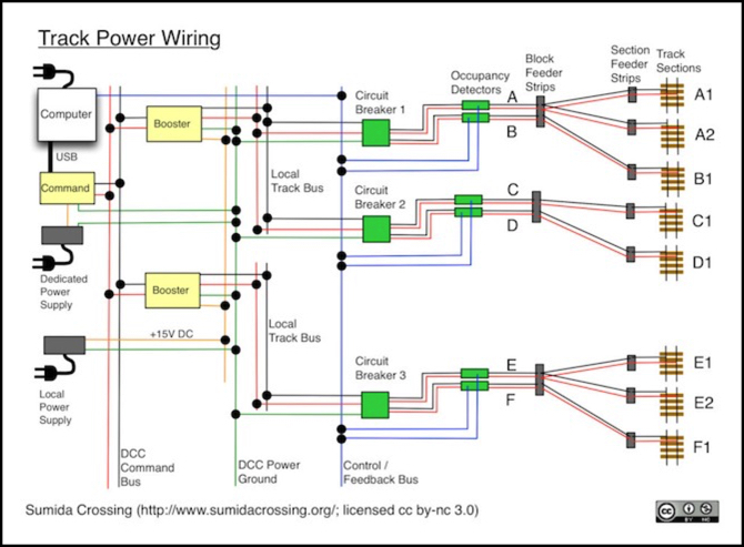
One implication of the above is that what runs between portions of the layout is not the DCC bus carrying power to the trains, but a low-current DCC command bus to which only boosters connect, plus a heavy-gauge DCC ground shared by all sections. Within a smaller portion of the layout, a local power bus will provide simple power to the boosters, and their output will go to sets of circuit breakers (probably via bus wires shared by several tracks within the area). This reduces the overall length of the high-current wiring, which helps to avoid voltage loss.
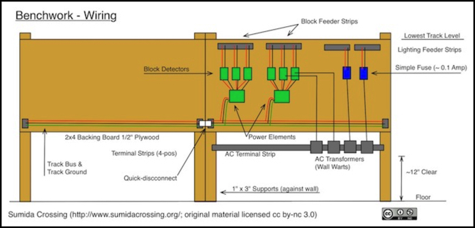
The following diagram shows how this would actually be installed on the layout (it omits the computers, boosters, and the track section feeder strips). The diagram is a bit out of date, and doesn’t exactly match the current benchwork plans. I’ll update it at some point.