


BDL168 Testing
Digitrax’s BDL168 is one of the most annoying, frustrating, and useful model train accessories I’ve ever dealt with. Although I’ve described its use on my layout on my DCC Protection and Detection Systems page, I’m going to use this page to describe the unit itself in detail and to discuss some of the “fun” I’ve had getting it to work. Note that my specific application derives from my layout design. There are ways to design DCC occupancy detection systems that share one (or no) PM42s among many BDL168s, and there are ways to design layouts that use fewer BDL168s than I chose to use. So don’t think that high cost of my approach is an absolute requirement. I’ll also note that I did not use “common rail” wiring, but what Digitrax calls “direct home” wiring. In fact, I take it a step further and gap both rails at every block, not just at booster boundaries. This is in a sense overkill (although I think it eliminates certain kinds of wiring errors, at the cost of a few more feeder wires) and you don’t need to work this way to use a BDL168. I’ll try to be clear about what’s required and what’s optional below.
The BDL168 is, at heart, four separate sets of four block occupancy detectors plus two independent sets of four “transponding” detectors. You can use these in various combinations. My approach is fairly straightforward: each of the four sections of a BDL168 is fed power from one of the four circuit-breakers on a PM42 DCC circuit breaker, and each circuit breaker is typically used for one track in a section of the layout (I have two DCC commuter line tracks and two DCC subway tracks in each “scene” of my model railroad). This keeps problems on one track from affecting others and problems in one part of the layout from affecting the same track elsewhere. It also requires lots of electronics, and gives me lots of occupancy detection sections (which I like having). This doesn’t really affect the operation of the BDL168, but it’s the reason for some of my wiring decisions, so it’s worth mentioning.
Note: “Transponding” is Digitrax’s proprietary method of receiving information back from a DCC decoder (in a train, typically). Most commonly this is used to learn where on the layout (i.e., in which block) a given DCC address is located. The BDL 168 reports this information back via LocoNet, the same way (but using different messages) as it reports block occupied/clear events. To use transponding you need to use a Digitrax (or other) decoder that supports it, and turn the feature on (typically by setting a CV; see the decoder manual). The NMRA is working on a different, multi-vendor system called RailCom, but it’s not as mature as Transponding today. And I’m using some trains that require special Kato/Digitrax decoders that only support transponding, so my choice was made for me there.
After an initial attempt at installing the BDL168s and RX1s directly on the underside of the layout, I decided to assemble each of these sets on a removable sheet of 1/2” plywood (18” deep by 24” wide), an approach suggested in their application note that facilitates maintenance and rewiring, as well as future re-use of these assemblies when the layout changes. Each board has one PM42, one BDL168 and two sets of four RX1 transponding sensors (each set is called an “RX4”, but since I’ll be referring to the individual sensors here, I’ll say “RX1”).
For computer logging I’m using a 2001 800 MHz G4 iMac (the kind that has the LCD on a stem) running OSX 10.5 with the most recent clean version of JMRI (Summer 2011), and a RR-CirKits LocoNet USB connection to the LocoNet. Even though the computer is old and a bit slow to load the software, I saw no problems with it during testing (I also did a few tests with a much newer Intel-based laptop for comparison).
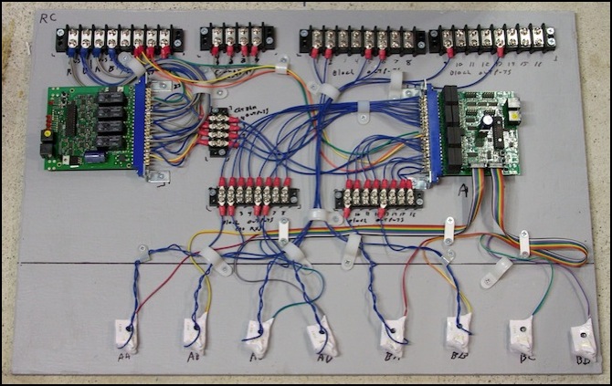
PM43 (left), BDL168 (right) and eight RX1 sensors ( labeled AA - BD here)
Terminology and Addressing
The sixteen outputs of the BDL168 are numbered 1 to 16. Each set of four corresponds to one of the power inputs, but that’s not described by the block numbering. The eight transponding sensors are a bit more confusing. The BDL168 refers to these as “A” through “H”, however most documentation refers to each RX4 set as “A” through “D” and the two inputs on the board are labeled “A” and B”, leading me to use “AA” through “AD” and “BA” through “BD” in all of my documentation to this date. I’ll eventually go back and correct this to the”A” through “H” nomenclature since what I most care about are the LocoNet messages, which use this. But for a time, both notations will be in use.
In LocoNet messages, the sixteen block occupancy detectors act like unique devices, and each reports with an Accessory Decoder address based on the ID assigned to the BDL168. These report back using “General Sensor Input” reports (opcode B2) while the RX1 transponding sensors report using an undocumented (outside of a brief mention in the application note cited below) “D0” opcode.
JMRI throws another couple of quirks into the mix, if you use that software. It numbers sensors starting from one (so Sensor address 0 is LS1, address 2 is LS3, etc). And it uses odd numbers in its “reporter” class for the transponding sensors, so RX1 “A” for a board with ID1 is “LR1” and “B” is LR3, etc.
Occupancy Detector Addresses
The formula to determine the address from the board ID and Output number is:
Address = (ID - 1) * 16 + Output
So a board with ID=3 would use 33 for the first output and 34 for the second.
I’ll be numbering my BDL168 outputs 401 and above (corresponding to BDL168 ID 26 and above) to avoid conflict with other systems.
JMRI uses the decoder address with an “LS” prefix as the sensor name, thus the first detector on a board with ID=3 appears as LS33 in JMRI.
Transponding Sensor Addresses
The formula to determine the “reporter” number used in JMRI for an RX1 sensor is:
Reporter = (ID - 1) * 16 + ((Sensor * 2) - 1)
where Sensor is a number from 1 to 8 (set A is 1-4, set B is 5-8).
For a BDL168 with an ID of 3, where the sensors are numbered LS33, LS34, LS35, etc, the RX transponding reporters in JMRI (prefix “LR”) are numbered LR33, LR35, LR37, etc.
One consequence of this is that it’s impossible to make the LR number match the LS number when there is a 1:1 correspondence between a transponding detector and an occupancy sensor (which is true of almost all of mine). That’s annoying, but ultimately not a serious problem as this all gets hidden from the user inside the JMRI configuration. I just need to keep a record of which sensor and which reporter is assigned to a track feeder (or electrical track block).
Documentation
And this brings up a point: Digitrax has done an absolutely horrible job of documenting the BDL168. The information is, I think, out there. But you have to dig for it, and “interpret” things, and realize that some of it dates from the days of the BDL16, or BDL162, which weren’t quite the same as the current BDL168. Probably the single most useful document is Digitrax’s application note on the PM42/BDL162 (PDF, hidden away in a Knowledge Base article on Transponding). Note that this is about the BDL162, so it’s rather dated in places. There’s also information on their Tech Support Depot Knowledge Base, and in the BDL168 and RX4 manuals, and in an insert that goes with the BDL168 manual (note: these are all PDF documents aside from the knowledge base articles). If you want nuts-and-bolts information about LocoNet packet formats, some is provided in LocoNet Personal Edition (PDF), but this omits definitions for some messages including transponding (which is partially defined in the application note).
Wiring
In DCC, the gauge of wire matters for two reasons: absolute current-carrying capacity, and voltage loss due to resistance in long runs. The maximum current-carrying capacity depends on heat, and limits are defined for wire in open air (which is what likely applies to most layout wiring) and in enclosed spaces (which could apply to a long feeder run within scenery). An Ampacity Table (like this one) is the place to go for that kind of information. What you’ll find is that even 22 gauge is fine for 5 amps in enclosed spaces and 7 amps in open air. If you’re operating an 8-10 Amp booster you need to step up to 22 gauge for open air, or 18 gauge for enclosed spaces. For feeders that will carry less than 3 Amps, you can get away with 24 gauge wires, which happens to be what Kato uses for its own track feeders.
Voltage loss is the other issue. The DCC limits there are nicely discussed on this page. What it amounts to is that heavy gauge (anywhere from 16ga to 12ga depending on current and length) is required in DCC bus wiring. However, for very short runs, particularly at amperages below 3 Amps, use of smaller wire is just fine. And that means wiring around the BDL168 can be of the small gauge required by it.
According to the application note the blue card-edge connectors are suitable for use with 18-22 gauge wire. My own experience is that use of 18ga stranded (not solid) wire is possible but very difficult, and you’re better off with 20 or 22 ga. Digitrax’s own manual makes frequent reference to 12 gauge wire, which would be impossible to use. The application note suggests use of terminal strips to convert between the local and bus wiring, and this is what I used. You could also use compression splices or just solder the larger wire to a short length of small gauge wire.
Each edge connector is apparently rated for 3 Amps of power, so if you’re working with a circuit breaker set to a higher value, you need to wire to both pins as described in the manual. The manual does imply this is optional for lower than 3 Amps, and since my PM42s are set to trip lower, I omitted the second pin originally to save time. Later I started using both as it made holding the wire in place easier even though it took longer to solder twice instead of once (and it makes the boards more flexible for future applications).
One of the quirks here is that the ground wire is only connected to one pin (and the manual makes this point multiple times). If you think of ground as “safety ground” or as a short-circuit protection (as it is on the booster/circuit-breaker wiring) this makes no sense, as it needs to be as big as the largest current-carrying wire. But the ground here is apparently just a reference so the voltage on a DCC wire can be judged, and as such they can get away with one wire. Note that this ground wire needs to connect to the ground used to link any circuit breakers back to the booster or command station, and that such wires should be laid out in a branching “tree” structure, and never in a closed loop. Having two paths to ground can be very bad, as it allows for all kinds of odd current behavior.
Power Supply (Internal)
The BDL168 itself needs a power supply and cannot be powered off the track. The BDL168 is varyingly described as needing a minimum of “12 volts AC or DC” or “12 volts AC or 13.8 volts DC”, with a draw less than 100 mA. So you might think track-power would work. But they really seem definite that it isn’t, probably to avoid problems during track power outages, so I didn’t even try.
The ambiguity in voltage requirements is a bit annoying: is the minimum 12 V DC or 13.8?. From the context, I think that 12 volts is safe, and they only said 13.8 because the new PS14 (which replaced the older 12-volt PS12) puts out 13.8 volts, and they’re now recommending use of it. The manual further notes that one power supply can power multiple BDL168s as long as the output is sufficient (100mA times the number of BDL168s) but that “no other devices” can share this supply. I think that’s mainly intended to avoid problems with transients in the power supply, which could be caused by a PM42 or a capacitor-driven turnout switch like the DS64, and I probably should be safe to share my power supply with devices like the SE8C signal control that aren’t likely to create transients. I’m using a regulated 12V DC supply of at least 1 Amp (and probably a 2 Amp one since I have a good source for those locally).
Testing the BDL168 Occupancy and Transponding
I set up a simple oval of track divided in two zones, and ran a loco equipped with a transponding-equipped decoder around in circles using my Zephyr command station as a means to check out the BDL168 wiring after assembling the board described above. The two block feeders could quickly be moved between zones, allowing me to check out all of the ones I’d wired up (I hadn’t wired all 16 on each board, as I was only wiring the BDL to the terminal strips in the middle of the board, and running wires from there through the appropriate RX1 sensors for blocks that would be in use. I could test occupancy alone by connecting the feeder to the mid-board strips if I wanted to.
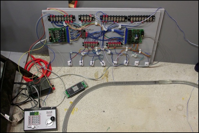
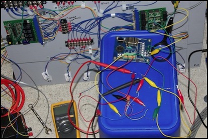
The Test Loop setup (note how close the feeder is to RX1s E and F in this photo; that’s a mistake)
One thing I quickly learned from this test rig was “honor the 2-inch spacing” around RX1 sensors. In the photo above you can see the feeder for one block runs near to two of the sensors. This caused them to not work in initial testing, and I lost some time assuming there were other problems before noticing the obvious.
While you can test completely from the computer log (assuming you have LocoNet and a LocoNet-equipped computer), Digitrax provides the LT5, a set of LEDs on a small board with a header block, with the BDL168. This can plug in to one of the four sets of “LED” pins on the board (see the BDL168 manual). I have a bunch of BDL168s, so I was actually able to connect up four of them at the same time, but you can move one around if that’s all you have. On these, the central LED reports power and (if blinking) transponding (I’ll come back to that). The four LEDs report status of the four occupancy sections on that part of the board (i.e., top right is 1-4, bottom right is 5-8, top left is 9-12, and bottom left in 13-16). Even with the computer, I found these really helpful.
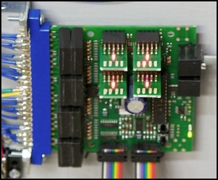
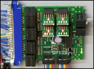
BDL168 with four LT5 LED sets: Block 2 (left) and block 12 (right) occupied
Transponding is a bit odd. The central LED will flash if transponding is detected in a sensor, but each of the four LT5s corresponds to one RX on each string, so the mapping is top right equals sensors A and E, bottom right is B and F, top left is C and G and bottom left is D and H. This can be rather confusing. Additionally, I saw messages in the computer log when the light wasn’t flashing at all, so it’s only partially reliable. I’ll come back to that when I get into my debugging of the transponding sensors down below.
A Typical LocoNet Log
The following is a typical set of LocoNet messages captured by JMRI with one locomotive (DCC address 3) on a loop composed of two blocks, wired to a BDL168 with the default ID of 1. The two blocks are wired to outputs 9 and 13 of the BDL168, with 9 looped through RX1 “E” (LR9) and 13 looped through “F” (LR13). Note the long delay (up to half a second on some transitions) between the transponding being reported out of one block before being reported in the next one. Note the shorter time for occupancy detectors to report (typically around 0.1 seconds, but sometimes higher).
This log has both timestamps (far left, down to the millisecond) and a hexadecimal display of the actual LocoNet messages turned on. I normally work with timestamps but without the Hex, as it’s not really adding useful info to the text messages.
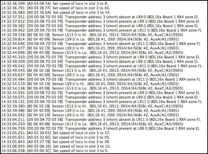
Note: the hex for the “B2” sensor codes above doesn’t match what the LocoNet Personal Edition suggests it should.
RX1 Sensors
While the actual BDL168 occupancy detectors seem bulletproof (all worked correctly and reliably), the same can’t be said of the RX1 sensors. Four of my eight didn’t work on initial testing. And I had problems with a fifth quickly traced to the test-track feeder hanging too close to the sensors on the board. What’s more, this isn’t a “hard” failure, as at least two of the failed sensors would occasionally make a report (in some cases they’d send LocoNet messages even when the LT5 light said they weren’t working). Since I had extra BDL168s, I was able to swap boards to prove it wasn’t a failure in the BDL168 itself. I also swapped the connections to the board from A to B (the problem followed the cable). And I rewired a couple of the sensors, which proved confusing as the problems persisted when I moved the sensor to a different block output (following the sensor) and when I moved the block output to a new sensor (following the block output, or indicating two bad sensors).
It’s kind of hard to believe a 50% failure rate on two different RX4 sets, so I’m suspicious of some kind of wiring error on my part, but just what is proving elusive. A simple check with a meter showed essentially identical resistance in all of the RXs, so it’s not a wire problem in the sensor, or at least not an obvious one.
I’d read that the BLD168 was sensitive to its power supply, so I switched to using a regulated 15V DC supply dedicated to it for testing. This didn’t change anything.
My suspicion is that it’s some kind of sensitivity (in the RX1) or noise (on the track) problem. With the train motionless I’ve seen the sensor for the block it’s in report present/absent/present/absent every few seconds. This was on one of the problematic blocks, so it may be related to just why this block is sometimes not reporting at all, but I’ve seen this kind of “sensor bounce” on “good” sensors a couple of times, so I’ll need to account for it when using these reports in automation software.
There’s mention in the Digitrax documents that transponding works by putting a load on the F0 output (the white wire from the decoder used for the headlight, connected to the blue common wire). In theory, it can detect even a 1.2 mA current (less than half the load of a typical surface-mount LED) on a system with 2-3 Amps of current (and the implication is that current has to be greater than 2% of zone current). My problem could be inadequate load, since I was testing with a decoder that used surface-mount LEDs (3 mA draw) on a decoder that pulls perhaps 20 - 60 mA, but even there I should be seeing about 5% load from the LED.
Digitrax recommends (RX4 manual, pg 11, PDF) use of a “270 - 470 ohm resistor” on the F0 output to ensure detection by forcing current to 20-30 mA on a 2 - 3 Amp zone (that’s 1%). I tested for that using my decoder tester with a DZ123 decoder, a full size bright-white (high current) LED and a 470 ohm resistor, generating a current around 20 mA on a zone with just 100 mA (20% rather than 2%). The problem persisted, so I don’t think an undersize resistor on the decoder is the issue here. However, this does make me worry that transponding may not work with the typical SMD-LED lighting used on N-scale trains if I get a fully-lit train in a transponding section, as 3 mA on 200 mA is just 1.5% (and thus right on the 1% - 2% borderline).
Note: I did have some problems with the first attempt to test this, illustrated below. In the course of this I “smoked” the DZ123. I cleaned up the wires, and switched from a small LED to the bright-white one described above, and broke out a new DZ123, and testing went much better.
Testing with a 470 ohm resistor
There’s another issue, that typically only applies to high-current environments (large scale layouts, or ones with lots of sound-equipped trains in a block). In these, you need to bridge the F0 output with a small 0.1 uF (micro Farad) non-polarized capacitor and a 100 ohm 1/8 Watt resistor in series (parallel to the light). The problem fixed by this will only occur in one orientation of the train, and picking it up and reversing it would make the problem go away. I’m not seeing that, but I may try this anyway.
Digitrax also documents a way to reduce the sensitivity of a detector, but this is likewise mainly an issue in high-current applications. I don’t think that’s my problem.
Since sensitivity seems to be ruled out as the culprit, noise is my next cause to investigate. Time to break out the oscilloscope and start looking at signals.
But for now, the mystery continues. This should work, and I’ve done what I think is a fairly complete job of eliminating potential problems, but without success. I may just give up and write-off use of transponding for now so I can get back to making the occupancy detector boards and installing them. The occupancy detectors themselves seem to work fine, and getting the track working is really the priority. I can leave this mystery for another day. But it is REALLY annoying.
January 2013
It’s time for a postscript. I never did more testing. My suspicion is that my problem lie with the RX sensors, but I’d bought and tested several, some old and dusty, some new, and all had problems. The BDL168 works as a simple occupancy detector, and so at least for now I’m going to ignore the Transponding capability.
And that “for now” is probably forever. In May 2012, the NMRA put out an update of RP-9.3.2 (PDF) followed by demos at the national show in August and articles in their Journal. All of this makes clear that Lenz’s RailComm is their not-yet-quite-standardized choice for what they call Decoder Transmission. RailComm is still in it’s early days, and it has a big hurdle to overcome for adoption: existing command stations need either updated firmware (if they support that) or an external device that adds a “cutout” to the signal, providing a window in which decoders can transmit. It’s going to be a long, slow process to widespread adoption of this, although I think there are enough potential benefits for people who built unified systems around them (ESU’s ECoS 50200 already does some nice things with decoder discovery, for example).
For now, I’m going to work with just simple block occupancy (via the BDL168). For my hypothetical future basement-filling layout (assuming I have a larger basement to fill) I’ll probably do something with RailComm if it ever gets off the ground, but that’s not “soon”.
