


Track Plan
Larger versions of these plans are available in Diagrams photo album.
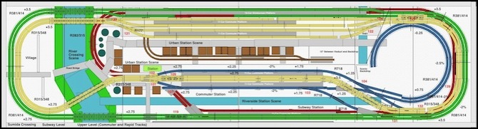
Combined diagram (showing underground “subway” in red)
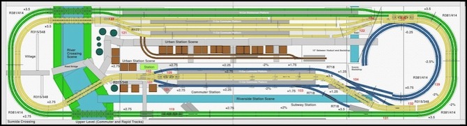
Above-ground tracks (Commuter in yellow, Rapid in green, descending track to subway/helix in blue)
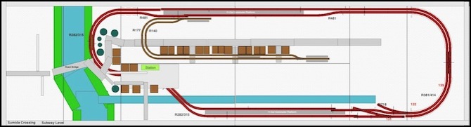
Subway (red) and Tram (brown) tracks
The railroad is an oval, with a center view block dividing it into three main scenic areas: the Riverside Station, loosely based on Ochanomizu Station in Tōkyō, the River Crossing, loosely based on the Sumida River, and the elevated Urban Station (pretty much free-lanced, but similar to many urban stations). At the right end, view blocks were originally planned to hide the return curves and a helix down to staging tracks. These were never built, and eventually work began on a Hilltop Scene above where the helix would have gone. The helix and associated staging was never constructed.
The staging tracks would have been located about 16 inches below the urban station, but a second set could be located under the riverside station by extending the two entrance tracks through, with a simple curve below the river scene. This would raise storage capacity from 10 trains to 20 trains. Alternatively, or in addition, some of the storage tracks could be extended straight under the River Crossing scene, to make them long enough for a full Shinkansen train (assuming a 16-car train can climb the helix, which might be a problem).
Although it may be hard to tell from the track plan, the three main lines (commuter, rapid and subway) are continuous double-track loops with connections between them. Any train can move from storage, through the commuter line to any other line. The tram line is separate and the trams only operate on it.
The yellow tracks represent a double-track commuter mainline, stopping at both stations. Stations on the commuter main can accommodate up to 12 EMU cars (e.g., a full-size 11-car Yamanote-line train or two six-car trains). The urban station has sidings to allow express trains to pass Locals on the commuter line. This is where most of the operational activity will be.
The green tracks represent a second line, which stops only at the urban station. This could be for Rapid (limited stop) commuter trains, or can stand in as a Shinkansen line, depending on what trains I want to run. The platform at the elevated station will accommodate a 16-car Shinkansen train or a 15-car outer-suburban commuter express (Rapid) train. Trains on this line will mostly just run in circles, to provide some background activity. For that reason, the lack of direct access to the storage tracks shouldn’t be a problem. Trains can still be moved to/from storage, they just have to go through the commuter line to do so, which is quite unprototypical for Shinkansen, given that the two use different gauge tracks in the real world.
The rapid tracks were wired to be operated on either DC or DCC and served as a test and break-in track for new trains before their conversion to DCC.
The blue tracks allow trains to enter and exit the storage tracks and the subway. Trains from the outer express line can switch to the inner commuter main using the cross-over at the right end so that they can move to and from the staging tracks.
The red tracks represent a subway line, located 2 inches (50 mm) below the other tracks, with a station in the Riverside Station scene viewable through cut-outs in the front fascia. The subway is at “ground” level under the elevated Urban Station. Trains from the yellow commuter main line or from staging can run in/out of the subway (which is prototypical for many of Tōkyō’s lines), and trains on the subway are visible as they cross the river in front of the riverside station.
Finally, the brown tracks represent a light rail or “tram” line, which operates an out-and-back service from underneath the elevated urban station to two other stops, both within the Urban Station scene. This had been planned to be automated with one or two trams moving back and forth on the line, but that was never done.
The elevations on the diagram above represent heights relative to the wooden table top, with “ground” typically 2.75 inches above it. This is achieved through two layers of insulation foam: one 3/4-inch and one 2-inch. The “ground” level in the Urban Station scene is at +0.75” (one layer of foam) with the upper tracks elevated in a viaduct station, and the lower (subway) tracks at ground level. In the Riverside Station scene, the upper tracks are at ground level (+2.75” here), with the subway tracks (still at +0.75”) underground.
As noted, the water level for the two rivers is 2.75 inches below the upper track level, allowing fairly significant relief at the river banks (34 scale feet, or 10.5 meters), as well as allowing space for the subway line below ground, yet still crossing above the water level. Originally I’d planned more layers, and five inches of total relief, but this didn’t look good in mock-ups, and resulted in height differences much larger than the prototype. Instead of using foam layers to cap the subway, I used 2mm styrene sheet.
Curves on the Rapid/Shinkansen line are 381/414 mm radius (15” / 16 1/4”), allowing use of the Kato banked concrete-tie track. Curves on the commuter main are 315/348 mm radius (12.4” / 13.75”), which exactly fit inside the larger curve, rendering the curve at the left end a four-track main. The subway uses 282/315 mm radius curves (11.1” / 12.4”), but these are out of sight. The tram line is much sharper, at 140/177 mm (5.5” / 7”) radius. Grades are 2%, except for the helix, which is roughly 2.6% (it uses 381/414 mm curves, which are the largest I can fit) to ensure 3 inches between loops. All switches are Kato #6 except the tram, which uses Tomix P140 turnouts. Clearances are more than 2 inches above rail-top, more than sufficient even with raised pantographs (the subway is slightly tighter, at about 1.75” clearance, which is adequate for the cars that will be used there).
The red numbers on the track plan are LocoNet addresses for the switches, used to throw them from the hand-held controller.
The track plan isn’t perfect; a couple of places don’t quite meet up, but it is close enough that it can be made to work. It was designed with Kato Unitrack in mind, although some consideration was made to allowing later conversion to flex track (e.g., all lines had cork or soft foam roadbed).
I wanted to have at least one grade-crossing, eventually planned to be across the yellow line at the left end of the riverside station. This would have used below-table Tortoise motors to lower and raise the crossing arms. In the end, this was another detail not completed.
By the way, if you’re curious the track plan above was made in RailModeller on a Mac. It’s a fairly easy to use program for quick-and-dirty planning with sectional track (it supports flex track too, but I find that aspect very hard to use), and is my primary planning tool. I’ve also been working on learning XTrackCAD, which is an absolutely horrible program to use, but much more flexible/capable than RailModeller (which itself isn’t the most Mac-like program in the world; it’s rather unintuitive at times).
