


Curved Track
With sectional track like Unitrack, constructing a curve is no different from constructing straight track: just snap sections together. But when working with flex track, constructing good curves is a little harder, partly because it is possible to do better than with simple snap track. This page covers issues related to this.
Curves have a radius, given in inches or millimeters. Model railroad curves are always much sharper than the prototype, which often have radiuses of thousands of feet or hundreds of meters. A curve can have a constant radius, which is called a simple curve, or the radius may change. The most common form of changing radius is an easement curve, covered elsewhere, which occurs at the beginning and end of a curve. But a curve could also change from one radius to another mid-curve, which is called a compound curve. In general, aside from easements, it’s preferable to build simple rather than compound curves. This is prototype practice unless there’s some obstacle that can’t be avoided, and it will look and usually work better.
Prototype Practice
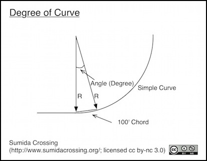
Outside the U.S., prototype railroads typically measure curves by their radius, just as modelers do. But in American railroading curves are usually described as being of a certain degree, which refers to the angle at the center point in a curve of the given radius having a length along a “chord” parallel to the track of 100’ or 30.48m. A one-degree curve thus has a radius of ~5,730 feet (1,746.4 m), and a radius half that equates to two degrees, and so on. That’s actually slightly rounded, with the real radius being 5729.57795 feet (1476.375 m). Or put in more simplified terms, Radius (in feet) = 5729.58 / Degree, and Degree = 5729.58 / Radius. If you prefer to work in metric, just substitute 1476.375 in those formulas to convert degrees to meters.
High speed rail will have curves of less than one degree, which even in N-scale isn’t practical as that’s a radius of more than 35 feet (10.6 m)!
One technical detail you don’t really need to know: in railroading, the 100’ section is not curved length along the track but the straight-line length between the two points where the radial lines meet the track, or a “chord”. In non-railroad (e.g., highway) work, the distance along the curve (the “arc distance”) is typically used. At the level of precision used in model railroads, the two are the same number for all practical purposes.
Kinds of Curves
Curves in model railroading are described by their radius, the distance from some center point to each point along the curve. This distance is typically measured in inches by U.S. modelers and model railroad manufacturers and in millimeters by everyone else. I tend to work in millimeters as I find dividing by tens easier than fractions, but I’ll give measurements in both here. As mentioned above, this radius should remain constant around a curve (except for easements).
A Simple Curve has the same radius at all points along the curve. A Compound Curve consists of two or more simple curves laid end to end. An Easement is a specialized type of curve where the radius varies along the length of the curve. Most layout curves should be simple curves with an easement at each end, although these aren’t used on low-speed curves and aren’t really useful of visually interesting on fairly broad curves. Compound Curves are generally something to avoid as they increase the risk of operational problems, but can be used to approximate an easement if you use sectional track. See the Easements and Superelevation page in this section for more about this topic.
Minimum Radius
The minimum possible radius of a curve will depend on the rolling stock used. One key aspect of this is the space between rigidly-connected wheels. Diesel or electric locomotives with four-wheel trucks tolerate sharper curves than those with six-wheel trucks, while non-articulated steam locomotives with many wheels are even less tolerant.
But often it is the coupling between cars that has the most effect. Body-mounted couplers are more sensitive than truck-mounted ones, particularly if the end of the body extends well beyond the truck. Passenger cars tend to be the most sensitive, as not only do they often use body mounted couplers, but they have passageway “diaphragms” between cars with very close clearance. Short freight cars and light-rail vehicles tolerate shaper curves than long modern freight or passenger cars.
The NMRA recommends different minimum radii of curves for different classes of rolling stock in Curvature and Rolling Stock (RP-11, PDF). The minimum needed for all classes in N-scale is 21.5” (546 mm), but for electric locos and passenger cars under 70’ length (21 m) this is reduced to 12.5” (318 mm). Many models will run over even tighter curves, but to be absolutely safe 21.5” should be used as the minimum radius. Note that this is a broader curve than that provided by most sectional-track layouts. If you use sharper curves, it’s important to test the specific cars you expect to run, just to be safe. I’ve found some North American passenger car models to be problematic on any of Kato’s track sizes, for example.
Another approach to choosing the minimum radius based on appearance comes from a magazine article (Powerful New Curve Radius Insights for Any Scale, by Joe Fugate, Model Rail Hobbyist Issue 1, January 2009). This suggests that the minimum radius of a curve should be chosen based on the length of the rolling stock using it. For good appearance, the radius should be 3.5x the longest car length when viewing from inside the curve or 4.0x when viewing from outside. The article also covers some functional aspects regarding coupling, and is worth reading for that if you plan to operate freight. My focus is on passenger trains, which aren’t normally coupled or uncoupled in operation (not the ones I run, anyway, that’s more likely with locomotive-hauled passenger trains).
In N-scale, typical Japanese commuter stock is about 135 mm in length, yielding a minimum radius of 472 mm (18.6”) to 540 mm (21.25”). But Shinkansen cars are more like 160 mm, yielding curves of 560mm (22”) to 640 mm (25.2”). If you run something else, your measurements will likely differ.
But for me, it looks like my minimum radii for commuter lines should be around 546mm, although tighter curves may be acceptable in yard tracks where appearance is less of a concern. For Shinkansen I’m going to want to make broad curves (e.g., 640mm and larger). One solution for this is to ensure that the Shinkansen line is on the outside of any curved portion of the layout, and for an around the wall layout that means putting it at the back. On a peninsula end, however, it would need to be at the front.
S-Curves
The bane of most beginning modelers, particularly with sectional track, is the S-curve. This is formed when two curves going in opposite directions are connected. It’s very easy to create these by accident. For example a switch for a siding naturally creates one since the straight track curves out and then curves back to become parallel in a very short distance.
S-curves are to be avoided at all costs, although sometimes they’re required (as in sidings). The problem lies in the couplers. When two cars are on the two different curves their ends are not pointed towards one another, and this can pull the couplers on both sideways further than they are able to handle. The result is that one car literally pulls the other off the track. With broad curves the effect is less, but any S-curve is still placing more force on couplers than the individual simple curves would.
The simple way to avoid an S-curve is to place a straight section of track as long as the longest car between the two curves. This will then act the same as a car entering a simple curve. If you use easements, these will extend in such a way that cars naturally align correctly where the two easements meet, eliminating the need for a section of straight track.
When an S-curve can’t be avoided, it needs to be treated with caution. Just as on a real railroad, a turnout into a siding should impose a very severe speed restriction on the operation of trains through the curve. And the use of larger switches (#8 vs #6, for example) can help mitigate the problem.
Track Spacing
The distance between parallel tracks (e.g., of a double-track line) is subject to two constraints on curves. The ends need to line up with the straight track leading into the curves. The curved tracks need to be far enough apart that long cars on one track won’t overhang too far and hit cars on the other track. This will typically be wider, which means that track spacing needs to broaden out either as curves are approached or within the easement leading into the curve.
Straight track spacing is described on the Track Standards for Straight Track page in this section, and that page also discusses some of the standards and practices related to track spacing on curves.
Standards
The NMRA specifies the following track spacing:
- 1.5” (38.1 mm) for modules (all curves and straight track)
- 1 1/32” (26.2”) on straight track
- 1 11/32” (34.1 mm) for 21.5” curves (546 mm), Class Ia (long passenger)
- 1 7/32” (30.1 mm) for 17” curves (432 mm), Class I (six-wheel diesel)
- 1 5/32” (29.4 mm) for 14.5” curves (368 mm), Class II (four-wheel diesel)
This means that except on modules, tracks will have to broaden by at least 3 mm (1/8”) and up to 8 mm (nearly 3/8”) for curves.
Other Standards
The NMRA isn’t the only standards body though. In Europe, MOROP defines standards based on European practice. While these often match the NMRA, to allow for interoperability, their track standards have some significant differences. These are probably due to differences in typical European track, which is often built with a smaller loading gauge than North American track, because land was already heavily-used by the time railroads were constructed in Europe. The MOROP standards for track spacing are:
Minimum Spacing (mainline): 25 mm
Minimum Spacing (station): 28 mm
- 550 mm radius curve: 26 mm
- 450 mm radius curve: 26 mm
- 350 mm radius curve: 26 mm
So curves broaden only slightly, and may even be closer together than if a station is near the end of the curve.
Operational Considerations
One thing that effects track spacing is overhang on long cars. On sharper curves, long passenger or modern freight cars will overhang to the inside of the curve significantly in the middle of the car. This can be enough to hit other cars. This is magnified when models of tilting passenger cars are used, as these tilt even further in, and it will be slightly affected if the curve has been superelevated.
There’s no general guidance on how much spacing is needed for this, but the NMRA numbers are probably a good guide here, as North American trains tend to use longer cars.
These numbers do not account for other clearances. If you model electrical lines, and need space between the tracks for power poles (or in yards for lights), this will be in addition to any space required here. Safety fences, often found between tracks in stations, are another clearance issue to consider. Signals are usually placed outside of tracks, or on overhead structures, but in some cases they can be between tracks, and the width of the signal head and any associated ladder must be considered when determining clearance, and thus track spacing.
And in a yard where you want to be able to place cars on a track by hand, sufficient space for the “five fingered crane” must be allowed.
