


DCC Voltage and Cab Lights
I’m turning my attention to the cab car decoder install now, and a recent discussion with Don along with a question from a reader had me thinking about potential problems with DCC conversion of N-scale EMU cars with cab lighting. And the one that really worried me was overvoltage from high DCC track voltages, and its harmful (fatal) effect on LEDs. DCC decoders essentially pass track voltage (minus a small bit) through to their function outputs.
By the way, larger versions of the lightboard photos here can be found in the DCC Decoders photo album. There’s also a new MA E231 album, although as yet it doesn’t have much in it.
Despite N-scale trains being nominally designed for 12 Volt DC systems, most of the ones available in the U.S. are probably designed to be safe to operate on typical HO-scale power packs producing 18 or even more volts, simply because such systems are the norm here. But that’s not necessarily true of all models. And in particular it may not be true of models produced for the Japanese market, which many of mine are.
Kato’s models are something of an exception, as not only do they make models of similar design to their domestic ones for export, they also sometimes export their domestic models for sale in the U.S. Further, while most Japanese manufacturers don’t pay much attention to DCC, as there is very little adoption of it in Japan, Kato resells Digitrax’s Zephyr, and provides decoders for many of their trains.
But most Japanese models are designed for the Japanese market, which is almost exclusively DC. And most Japanese DC power packs have a maximum rated output of just 12V (and may produce less), deriving from the original manufacturer standard for N-Scale. There’s a potential risk in taking such models and putting them on a DCC layout, that components designed for a maximum of 12V DC will fare badly when asked to handle higher DCC voltages. And on reviewing one sample, my Micro Ace Sobu E231, I discovered that it wasn’t really designed to handle more than about 12-14V before overloading one of its components. Suspicion confirmed: I have something worth worrying about here.
I’ve done some research into just what that worst-case could be (written up on a DCC Voltages page in the decoders section), and I’ve come to the conclusion that, aside from some historical systems that could still be out there, current systems aren’t likely to produce in excess of 16V DCC at the track, although there could be exceptions. And most are under 15V.
What this means is that in doing my decoder conversions, I may need to make some changes to account for higher voltages, at least on the lighting, but those don’t have to deal with a larger overvoltage, merely an extra 33% (4V). Motors aren’t as sensitive, and the use of PWM there means that unless you set the throttle to 100%, they’re not receiving the full power of a 16V (or whatever) track, but some percentage of it, even though the peak voltage is still based on the track voltage.
If I design for 16V I’m probably safe even if I someday take my trains to someone else’s module or home layout that isn’t set up specifically for 12V operation; designing for 18V would give me a larger safety margin, but probably isn’t necessary. Note that with LEDs, a resistor designed for safe operation at 16V will cause the LED to be a bit dimmer at 12V, but likely not a lot, and it will also extend the life of the LED. If I’m building my own lights, I can just wire them assuming 16V and not worry. But if I’m working with an existing lightboard, particularly if I’m trying to preserve as much of the original circuitry as I can, then I have to worry about the difference between 12V and 16V.
And to an extent it’s easy to figure the size of a resistor to convert 16V to 12V assuming you know the current. Ohm’s Law (V=IR, or in this case R=V/I) says that this needs to be 40 ohms (an a half-watt per P=I2R) at 100mA (typical of normal operation for a small motor), 200 ohms (and much less than a quarter-watt) at 20mA (typical of a LED headlight) or 800 ohms at 5 mA (typical of some surface-mount LEDs). I’ll come back to this point below.
Japanese Models
In the U.S., and perhaps also in Europe, HO dominated for so long that N-Scale model trains are probably designed assuming they’ll be used with a typical 16V DC HO power pack. So it’s reasonable to assume that their circuitry can tolerate 16V (although even there, DC trains aren’t run at full power all the time, and doing so could stress the electronics).
My specific modeling is with Japanese N-Scale model trains, however, and Japan really does use 12 Volt DC power packs. Power packs for HO are clearly marketed as “high power” (Kato, for example sells a 15V “Hyper-D” pack for HO). And since most modelers use N-Scale, most power packs are designed for that.
I have both Kato and Tomix power packs, and both have a maximum (nominal) output of 12V. Some power packs aimed at Japanese tram (light rail) modelers reportedly put out at most 9V. If all the power is 12V, then it’s reasonable to suspect people designing the trains weren’t too worried about encountering significantly higher voltages.
Checking these out, both Tomix packs, when connected to a Japanese-standard 100V AC supply, product 10.9 volts at the track (without a load; this will drop if there’s a running train on the track). Oddly, the Kato pack, despite being rated the same, put’s out 14.8V when connected to my 120V wall outlet (it’s not a Japan-spec model and the wall-wart transformer is rated for U.S. voltage). I suspect that’s due to it being a Kato USA model, designed for the U.S. market. It’s probably intentionally high.
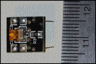
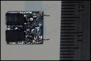
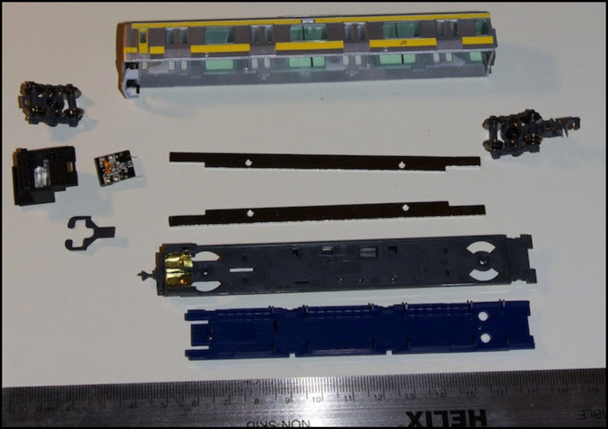
MicroAce E231 Cab Lighboard, front (left) and rear (right)
So, let’s turn to a typical lightboard for cab head/tail lights: the one in the MicroAce E231 I’ve been working on for the past few weeks. This has three medium-sized small LEDs, and one resistor marked for 680 ohms (“681” = 68 x 10n, where n=1). Although I haven’t traced the wires, observing the board in operation showed that one (yellow) LED was for the destination sign, and one each was for the (white) head and (red) tail lights. All three are the same size, about 3mm on a side, meaning they’re likely in a 3525 or roughly similar package (per this chart from Wikipedia). Also, since there’s only one resistor, they’re clearly wired in series with it.
Consulting a couple of typical data sheets for that size LED (google is handy for this) shows that they’re probably going to have a forward voltage of 2.8-3.8V(white), 1.7-2.4V (red) and around 2.0-2.6V (yellow), although this varies a lot. LEDs this size would be limited to a maximum current of 30-50 mA (white), and below 30 in some cases (one yellow was rated for 25mA, another for 20mA), with typical being 20mA. The higher the voltage across the LED the more current, and the brighter the output, up to the failure point.
Calculating LED current draw is difficult since it and voltage across the LED vary in a fairly complex manner and with two LEDs, they need to reach a balance where both drop different voltages at the same current, and the sum of those plus the resistor drop add up to the power supply total. Fortunately, I can just measure it for known voltages.
Measuring the Lightboards
I tested three cab cars from MicroAce, Greenmax and Kato by placing them on a track connected to my Kato pack, running it through the RRampMeter (to provide a DC voltage reading) and my multimeter (to provide a more precise mA reading than the RRampMeter is capable of). The Kato and MicroAce had similar power requirements, rising from 7.4 and 9.5mA at 7.5V, to 12.7 and 16.5mA at 12.0V to 16.1 and 21.1mA at 14.8V (all numbers for headlight-lit direction, but taillight-lit dropped the highest less than one volt). So I can probably assume fairly similar designs between the two of them.
Oddly, My Greenmax 10000 subway train’s power needs were much lower, ranging from 1.0mA at 7.5V to just 2.3mA at 14.8V. I’m going to have to take that apart and see what makes it different, but that’s a project for another day.
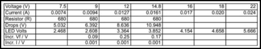
MA E231 Cab Lights (tail light numbers) with extrapolated current and voltage-drop numbers
Note: I only tested down to 7.5V because that’s the minimum at which my RRampMeter will reliably work, and my multimeter was busy being part of the circuit to measure the current.
Using the MA numbers, the voltage drop across the LEDs ranges from 2.468 to 3.852 V (that’s V=IR applied to the measured voltage and current and the known 680mA resistor to tell me what’s left). And the number increased by under a quarter volt per applied volt, so I can use that to extrapolate worst-case numbers of 4.2V @ 16V, 4.7V @ 18V and 5.7V @ 22V. Similarly I can do the same to estimate current draw. This isn’t guaranteed to work (LEDs aren’t linear, and that’s a linear model I just made), but it’s reasonable for a back-of-the-envelope estimate.
Looking back at the LED specs, I can’t drop more than 2.4+2.6 = 5.0V, so I could be safe at 18V, but not much higher. However, the LEDs don’t necessarily increase at the same rate, and as noted the model is imperfect, so I shouldn’t cut that close. It does suggest I’ll be safe at 16V though. Now for current: again, 18 should keep me below the worst-case 20mA number, so again I think my operating range will be okay.
But don’t breathe easy just yet. There’s another formula that comes into play here: P=I2R, or Watts equals the square of the current times the resistance, which matters for the resistor in the circuit. The resistor, based on close examination with a magnifying glass and my new digital calipers (I finally bought a set), appears to be 1.25mm x 2.0mm, which thanks to this handy table means it’s in an 0805 case and per various other data I found, those are rated for about 100mW (some are rated for 125mW).
So, working backward from that, and the power formula which can be restated as I = SQRT( P/R ), where P=0.1W and R is my 680 ohm resistor, this means that more than 12.1mA is potentially going to be a problem. As you can see, I’m exceeding that at even 12V, although just by a hair.
Now the resistor undoubtedly has a safety margin, and it might even have a significantly higher power rating; I don’t know what components they really used, after all. But this tells me that my plan to use the pre-existing lightboard with a DCC decoder output may run into problems, as the components on it appear to have been sized for a maximum of 12V, and except on my DCS 100 which I’ve set to “N Scale 12V” output, there will be more than 12V on the track. Limited use probably won’t destroy it anyway; resistors aren’t quite as fragile as LEDs, although you can cook them to destruction.
Now I’ve omitted one thing that’s on the lightboard: diodes (there’s also a capacitor, but it doesn’t affect this). If I assume these are acting as a rectifier for the board, there’s probably always one in series with the LEDs (see diagram below). And there’s also a rectifier on the decoder. Between them they could be dropping a bit more than a volt. It’s hard to be sure what that would do to the current, but it probably drops it proportionally, which means I’ve got another volt (give or take a bit) of headroom in the track voltage. Still not enough to make me feel really comfortable even on a Zephyr, much less an HO command station. I’m going to have to take some additional mitigation step. But first, let’s take a look at that lightboard.
MicroAce Cab Lightboard Circuit
The number board (yellow) LED needs to work in either direction. That means that there’s some kind of rectification going on for the yellow LED, and perhaps some reverse-current protection for the others. Likely a rectifier, or since we’re looking at two small black objects on this lightboard (see back photo above, right next to contact whiskers): a half-wave rectifier made from diodes. It would appear from the placement of the solder pads, that the end of the resistor nearest the edge of the board connects through the two diodes to the power pick-ups, and that means there is always one diode in the circuit.
A bit of examination, and some thought, suggests that they’re roughly arranged as shown in the diagram below. I’m omitting the capacitor, as I’m not sure where it fits or what it does (it probably helps avoid flicker from dirty track, but it’s hard to know for certain). With this, the headlight will light when the right rail is positive (train moving forward) and the taillight will light when the right rail is negative (train in reverse), but the number board light will always be lit. Note that the same circuit can be used for both cabs, since “right” changes when the cab is facing the other way.
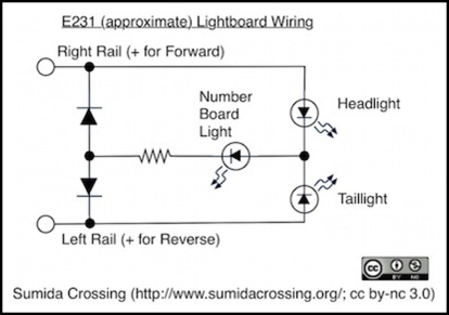
Basics of the E231 Lightboard Circuit (not all components shown)
The resistors appear to be about 1.3mm x 3mm, but I think some of the length is solder, so they’re probably also in the 0805 form factor. A typical low-power diode in this size, rated for 20V and 100mA will drop about 0.4V, as I assumed up above.
Mitigating the Risk
What to do? Well, first, I can assume I’ll never run this on anything other than my layout with its DCS 100 set to 12V output. That’s likely true, but it would be a rude shock if someday I forgot and took a train elsewhere, and fried it. Another option would be to put a resistor in series between the decoder and either of the lightboard contacts as described up above. And, given what I have, and haven’t, found for DCC command station voltages, I probably need to worry about 16V DCC systems, but nothing higher than that, despite what the standards say.
If I want to drop a further 4 volts, adding a 330 ohm resistor (R=V/I says 4/0.01212=330) will do it, and that’s even a standard size. Power dissipation in it (P=I2R) is a mere 48 mW, so that’s no problem.
That is not, however, the only possible solution. Because the limiting factor here is the power through the resistor on the lightboard, what if we could reduce power without reducing voltage? Sounds like a violation of Ohm’s law? No, it isn’t.
If I’m driving the lightboard with a bipolar decoder output to avoid having to rewire it (and that’s the goal: simple wiring), and I’m using a dedicated decoder (as I am, since I’m in an EMU cab car that lacks a motor), then I can use a motor decoder and connect the motor outputs to the lightboard. That’s bipolar, and will reverse polarity when the train reverses. And what’s more, the output is PWM. And PWM will output full track voltage (less decoder loss), but it doesn’t have to output the full power that that voltage is able to supply, because it’s only outputting full power some of the time, the rest of the time its output is zero, and those average to provide the power.
Now that trick won’t work with a decoder that has bipolar function outputs, unless they did something clever. More below.
So, the basic idea for using a motor-decoder as a bi-polar lightboard control is to take a decoder, program it with a speed table that is giving me no more than 75% motor output at all throttle settings (other than zero). Then, with 16V on the track, the averaged power going into the resistor is about the same as that on a 12V DC system, which it can handle. I don’t even need a voltage-dropping resistor. And I can set it lower to provide a safety margin. The downside is that at zero throttle, the head/tail/numberboard lights go out. I can’t prevent that with a speed table, since “throttle=0” isn’t one of the entries in the table. Zero throttle is assumed to mean zero motor speed.
Mind you, regardless of the PWM adjustments, at more than 18V DCC I’d exceed the maximum voltage across the LEDs. If I wanted to be safe on really high voltages, I’d still need an additional dropping resistor.
But for an HO-sized DCC layout that isn’t exceptionaly overvoltaged, either a 330 ohm resistor or a speed-table adjusted PWM output is going to be an acceptable solution, even for a lightboard like this one designed for a 12V operating domain.
Lenz Bi-polar Decoder
Lenz makes a function-only decoder with two bi-polar function outputs, the LF101XF (typically US$22), which others have reported using with some success. Its one downside is that it’s a bit large: 22 x 12mm. After chasing myself around the barn a few times with various other plans, I’m now thinking that I want to use these for my cab head/tail-light controls despite the size. At least until someone comes up with a smaller bi-polar function decoder (you know who you are...).
One of the cool things about the Lenz is that the bi-polar outputs are real function outputs for lighting. That means that they don’t turn off when the throttle is set to “stop”. They also support dimming, and while you could tie that to a function key and use it for rule 17 lighting (dimming headlights when in a station or passing another train), you can also use it to lower the normal setting of the output. And it’s implemented via PWM also, so in terms of reduced power without reduced voltage, it’s going to work the same way as the motor PWM outlined above. I may do the resistor trick anyway,
Warning: all of this is somewhat specific to this lightboard, and there could be aspects I’ve overlooked. It’s certainly possibly you could do all of the above, and still fry a LED on an HO-size DCC layout, either because I’ve overlooked something, or because your board is just enough different in component rating not to have the same tolerances as even this one. Don’t take this as gospel, and do perform your own analysis. Or find a professional decoder installer who will guarantee their work for the cost of the model (I’m not sure there is such a beast, but you could look). In short, I think things work this way, but I’m hardly an expert, so don’t blame me if they don’t. That said, I’m about to trust one of my expensive models to a DCC conversion based on this, and assuming it works, more will follow.