


Signals and Signaling with Arduino
I’m going to vary from my normal focus on modeling Japanese railroads today to talk about signals and modeling them in a more general sense. Heck, who am I kidding, there haven’t been many posts on modeling Japanese railroads of late. But I digress from my digression. Back to the subject: signals.
If you want to cut to the chase: I’ve written an Arduino library for controlling lineside LED-based signals. It’s only part of a complete signaling system that I’m working on, and at present you’d have to do more work to make practical use of it. But the code is public and can be used independently of anything else I’m eventually going to create; skip down to the end for details.
Why Signals Matter
Lineside signals are a common feature of real (what we modelers call “prototype”) railroads that often aren’t modeled at all, or at best poorly. Good signals can improve the sense of realism of a model railroad. And that’s true regardless of whether you want to operate trains in a realistic matter, or simply run them around the track. But good signals can be somewhat complicated, and until recently there has been a lack of products available to make them work in a realistic manner.
In recent years improved systems, both stand-alone and based on a central computer, have become available. These have several problems. They’re often very expensive, and either operate very simplistically, or require the modeler to be an adept programmer. It really shouldn’t be that hard.
When I first planned the original Sumida Crossing, signals were part of the design from the beginning. I even bought some of the needed electronics to set up a centrally-controlled system using a computer running the JMRI software with Digitrax electronics. I never got around to building that, in part because I had other things to work on. But as I’ve considered the layout’s replacement, signals are again important, and some of what I didn’t like about the first approach has been nagging me to find a better solution.
What I didn’t like in particular was the dependency on a central computer. That approach is in some ways simpler: there’s one place where all the control logic goes, and it’s in software so it is easy to change. And programming doesn’t scare me; my skills are a bit rusty, but I was originally trained as a programmer. I could still end up doing that, but at the moment I’m leaning in a different direction.
Real railroad signals are part of a distributed system, with fairly simple logic (of the form “is this track occupied or inaccessible?”) replicated in many places. The parts work together through simple communication. It’s a design dating back to the late 1800’s (and not much changed since then), and easily replicated with relatively simple circuits today. There may be external control, from a dispatcher or someone else, but even that can be distributed, with a local station master controlling some signals, and a dispatcher controlling others.
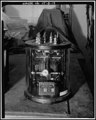
Signal Control Relay, New Haven RR, design c. 1905 - 1915, in use c. 1979
Library of Congress HAER collection
And while I’m not very good at complicated electronics, recent developments allow replicating that circuit logic as software in simple and inexpensive “embedded processing” systems. And so I started to think about what it would take to make a modular distributed signaling system based on Arduino microprocessors. The result, at least from a back of the envelope estimation, appears to be practical and likely to be significantly less expensive than alternatives. And it covers more than just signals, since a signal system needs to be tied into both block-occupancy detection and turnout (track switch) control systems.
Signaling won’t be cheap. A typical turnout costs around US$25, but on a mainline there may be multiple signals, ranging from US$15 to US$40 associated with each one. Then there are turnout motors (often costing US$15 to US$30) and occupancy detectors (US$10 to US$25). And that’s before you add any control logic, which can run to hundreds of dollars per set of signals, although centralized systems can spread that cost, at the expense of a lot of wiring. But my intent is to tie a bunch of these elements together with a relatively small number of US$10 controllers. And I’m looking at using inexpensive (US$10 or less) servo motors in place of the more expensive turnout motors as part of this system.
I also want to keep the option for external computer monitoring and override control, without making the central computer a required part of the system. There’s more than one way to go about that aspect, and I’ll discuss them in a future posting. But first, I’m going to start with the signals themselves, as these are fairly complex. In some ways, the signals are the hardest part of the whole system.
Prototype Signals
Lineside signals are a feature of just about every railroad everywhere, with the exception of some very small ones. There are a small number of lines that use signals internal to the train (cab signals) and dispense entirely with the lineside ones, but that’s still signaling. Why are they so common? Because signals do two things: they make the railroad safer by alerting the operators of trains to conditions beyond their view, and as a result allow more trains to use the same track in a given interval of time, increasing capacity (and thus revenue). Despite the fact that they’ve been around since before electricity (the early ones used oil lanterns at night) there’s a lack of consistency in what signals look like and what they mean. There are, however, some basic concepts all signals share.
What signals display are based on four possible inputs:
- The first input is permanent track limitations: you’ll never get a “clear” (full speed) indication when taking a diverging route through a normal switch. Speeds through switches are limited by the design of the switch (and other things beyond it). This is why speed-based signal rules generally specify one speed until you pass the signal or go through a set of switches called an “interlocking”, and another beyond that until you get to the next signal. Switch limitations are typically for a medium speed, although faster speeds are allowed though high-speed switches (usually called limited speed, although the Japanese term is translated as “reduced speed”). Track entering territory without signals (like a siding) may be more severely limited.
- The second input is the set of conditions in track blocks ahead of the train. The actual number of blocks will vary depending on the rules used by an individual railroad. For example, per the rules used in the Eastern U.S. and Canada, with a single three-color light, you can indicate conditions three blocks ahead (red = next block occupied, yellow = second block occupied, flashing yellow = third block occupied, green = all three clear). Track conditions are usually based on occupancy detectors, but can also report things like landslides blocking the track, flooding over the track, or some other kind of “don’t come here” emergency system.
- A third input is routing through one or more switches. This is related to the first one, the physical plant, but it is dynamic, with limits imposed or released when the switches change position. It’s also related to the second, because which block is “ahead” depends on the routing.
- Finally, some signals are under control of a central authority (a dispatcher or a station or yard master within a station or yard, or similar). On mainline, this can be used to set a line to allow traffic only in one direction, or to directly control signals to force them to be red (e.g. if a fire department calls to say that there is an accident at a grade crossing, or hoses are being laid across the track), etc.
Note: the examples above use U.S. speed signaling terminology, and Japanese signaling is very similar, although it is something of a mix of speed and route signaling. In true route signaling the meaning of the signals differs, but the reasons behind those (the inputs) are essentially the same.
The arrangement of the signal lights (the physical signal) and the way they are lit define an “aspect” for the signal. And railroad lines have differing rules on the interpretation of those aspects, called the “indication” of the signal. I’ll briefly cover those below.
Physical Signals
Modern signals display colored lights. A “mast” (the pole) can have multiple “heads” (the black backdrop around one or more lights), and a head usually can display red, yellow or green (or one of those colors flashing). Some railroads use more than one light on a head simultaneously for additional meanings. Japan’s standard signals do this, as do British systems and many U.S. subway systems.
While heads are often located above each other for a single line, sometimes they are arranged horizontally, or with subordinate heads below and to left or right of the primary head. Special “marker” lights, effectively a single-light head, can be above, below or to either side (and there may be multiple of them). In the signal shown below, the fact that the two main heads are on different sides of the mast actually changes the interpretation of the signal (it is one way of showing that red means “stop and proceed” rather than “stop”). In Japan, the same arrangement would mean that the lower head was for a route diverging to the right.
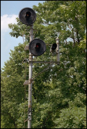
Signal with two heads plus a subordinate light (on right)
Even the heads used for the main signals can have different physical forms (for some typical Japanese ones, see my Example Signals page). The ones shown above are “searchlight” signals where one lamp can take on different colors. This form was once very common in North America, but has been replaced in recent years with signals using multiple single-color lights on each head, as these are less expensive in the long term. Note: all pictures were taken from outside railroad property.
Another form that was once common in North America (and is used for one type of signal in Japan) involves lights arranged in a pattern (which may or may not have colors). But in general, on one railroad, it doesn’t matter if “red” comes from one of three lights or from a single multi-color light or from a horizontal row of white lights interpreted as equivalent to red; the shape of the signal is irrelevant, the color and relative arrangement of lit lights is what has a meaning. There are exceptions, where the shape of a signal head matters, and often a sign attached to a signal mast modifies the meaning in some way. But color and position are the primary determinants of aspect and thus indication, in part because that is all that can be seen at night.
That meaning, however, is not uniform. Some countries have adopted common rules within their borders, but even then there are often variations for specific lines. Japan has standards issued by the Ministry of Land, Infrastructure, Transport and Tourism. North America is particularly bad, as every railroad seems to have done things just a little differently from their neighbors.
Often there are similarities, but once you get down to details almost every railroad has unique ways of doing things. Red usually means stop, but while in Europe it’s usually an absolute stop, in North America it’s often a permissive “stop and then proceed” (an indication also used in Japan), and mixed with other colors in the U.S. it can simply mean “use a slower maximum speed” or “this head has no meaning”, which can be confusing to European railfans who have experience with very different methods of signal use. In Japan, red on one head may simply mean “this route is inaccessible” when there are multiple heads for separate routes.
There are also two significantly different approaches to using signals. Some railroads use signals to describe allowable speeds (speed signaling) and others use them to explain what path the train will be taking though switches (route signaling). Both of these overlap somewhat, as routes imply speed and speed can often imply route to someone who knows the line. And, in general, people operating trains are required to know the line they’re operating over. Japan uses something of a hybrid system, where heads provide speed signaling but multiple heads or subordinate markers are used to describe different possible routes. If you want to model a specific railroad, you’ll need to pay attention to the details of how they use (or used at the time you are modeling) signals.
Finally, at least in the U.S., one railroad should have uniform rules for what indication (meaning) is given by signal aspects (lights), but the actual signals can vary a lot from line to line due to past mergers. Nobody goes around replacing signal masts just because they bought another railroad. At most they change the way the lights are used, and add those new signal types to their rulebook. Eventually those will be upgraded to some newer system, and commonality imposed, but that kind of change takes decades because it is very expensive.
For example, under one commonly-used system there are nine different mainline signal aspects that mean “stop and then proceed at restricted speed”, and four additional ones used in yard signals that have the same meaning. These aren’t all used on one line. Rather they reflect multiple past owners of different lines. So if you are modeling a specific prototype, you may need different signals depending on the past history of the line being modeled.
If you want to understand signaling better, most railway operating rules describing signals and how to interpret and respond to them are available online in one form or another, although sometimes you need to know the name of the rules to find them (like NORAC for most of the eastern U.S., GCOR for most of the western U.S., and CROR for Canada). You can also search for specific railways (for example there’s a good YouTube series on CSX signaling, although it appears to be somewhat specific to their southern-U.S. lines). And note that individual railways or lines in North America all have individual quirks of usage or interpretation, even when they share the same rules. Japan is apparently more consistent, but there are still variations (e.g., special signals used on transit lines, and others for high-speed lines with lineside signals; Shinkansen lines appear to only use cab signals and don’t have lineside masts).
Signal Behavior
Signals aren’t just lit in a specific way, either. As mentioned above, sometimes one or more of the lamps will flash. Sometimes all of the heads are dark.
As a general rule, all of the main heads on a mast will be lit, or all will be dark. Marker lights can be lit independently, but would only be lit if the signal heads were also lit (at least, I’ve not encountered an exception, although I suppose it is possible). Signals will be out on modern railroads if there is no train approaching the signal (i.e., in the block facing the signal). That’s both a power-saving measure, and a means to extend the life of the bulb. According to wikipedia this is called Approach Lighting, and railroads in the U.S. have been doing it since c. 1900. A dark signal, just in case a train did encounter one, is always defined to be equal to the most restricting aspect the signal could have displayed as a fail-safe measure. That means it’s either a “Stop” or a “Stop and proceed” for most signals.
By the way, although I said that approach lighting depended on the block in front of the train, that’s not entirely true. On double-track used for bidirectional running (and I’ve seen this in person), both signals (one on each track) will be lit if there is a train approaching either signal. That’s a safety behavior to avoid misreading the other line’s signal if yours is broken and theirs is lit for some reason. So approach lighting really depends on all of the blocks facing the signal, even if there’s no connection between the parallel tracks.
Finally, a “lit” signal lamp may actually be flashing because of the information it needs to provide. While some flashing lights, such as grade-crossing flashers, will go fully dark for as long as they are lit (called a 50% duty cycle), a flashing railway signal is somewhat different. This is likely to make it easier to tell that the head is there and flashing at a glance, rather than dark. While there’s some variation, in general for a lineside signal the lamp will be lit for significantly more of the cycle than it is dark (a greater than 50% duty cycle).
In some cases the lamp never entirely goes out, in others it will go dark briefly. In one video that I measured on a frame-by-frame basis, a modern signal head was brightening for 0.3 seconds, fully lit for 0.3 seconds, darkening for 0.3 seconds and dark for just 0.1 second (the cycle time for flashing U.S. signals is generally 60 flashes-per-minute, or one second per flash, although that can vary by about 10% from signal to signal). As far as I know there’s no standard in the U.S. for either the flash rate or the duty cycle, but it seems to be true of both old and new signals. This behavior may originally have been due to the fact that bulbs take time to come to full intensity and then time to drop to dark, so even if a relay was only on for a 50% duty cycle, the bulbs might have been lit more; I suspect it’s deliberate, at least on newer systems that use LED-based lamps, and perhaps it was always deliberate. Regardless, that behavior is important to capture in a good model: rather than simply blinking a LED on and off abruptly it needs to ramp up and down in intensity, with a significantly longer lit interval than it is dark.
Note that grade crossing flashers behave very differently from lineside signals. The rate is typically slower; I’ve seen 50 fpm used extensively in both the U.S. and Japan (per YouTube videos I’ve timed), and a limited selection of Australian signals also showed 50 fpm, although one appeared to be closer to 40 fpm. Additionally, they don’t ramp up in intensity the way lineside signals do, but basically go fully lit in a very small fraction of a second, and turn off equally fast.
Modeling Signals
Trying to reduce all of the complexity of prototype signaling down to a model requires a form of selective compression. Just as we can imply the existence of an oil refinery with a couple of tracks and some pipes, we normally use a subset of all possible signals and their modes of operation from a given railroad. Doing this requires understanding how signals are used on the specific railroad you want to model, which you can best learn by studying real signals on your prototype, and the context around them.
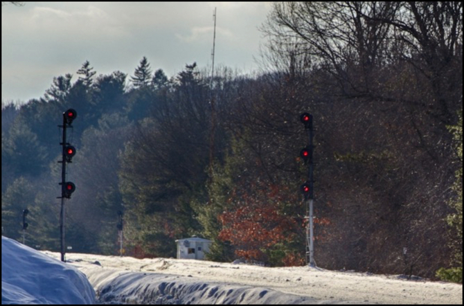
Consider the signals at the top of this post, which are part of a set of four (you can just see the backside of the others to either side of the left-most signal). These are located on a stretch of double-track mainline protecting a double crossover, and in the direction past the signals there is a passenger station a short ways ahead, while behind the photographer the line continues uninterrupted for some distance. The line is mixed passenger-freight, with short (1.2 mile, 2 km) blocks typical on this stretch.
What matters here is that there are three heads on the near side signals, but only two on the other. There’s a simple reason for this, based on how the heads are used. Each head can display three colors, and can be continuously lit or blinking, for a theoretical 216 different aspects (six cubed). In reality, the operating rules of this railroad only use sixteen of those aspects. And two of them are different ways of saying the same thing, so there are really fifteen “indications” possible.
If you only had two heads, the rules would limit the signal to twelve different possible indications. And most signals along this portion of the line, except at interlockings where tracks diverge, use two-head signals. This railroad, like many east of the Mississippi, uses speed signaling, where the top head describes full speed, the middle a medium speed and the bottom a slow speed (combinations can describe a couple of additional speeds). So, for some reason, the railroad needs to use at least one of the additional three indications here to limit trains to slow speed in one direction, but only limits them to medium speed in the other.
A bit of thought yields the obvious conclusion that the crossover switches likely limit trains in either direction to medium speed (although they could be high-speed switches allowing limited speed, which also requires the middle head), but that slow speed is required because of the adjacent station. There could be other reasons, of course. But it won’t be arbitrary. Those extra heads cost money, in lamps, control relays, wiring, and ongoing maintenance of bulbs and electronics. I’ve read that a typical single searchlight head costs CA$20,000, and that’s only part of the cost. Railroads never spend money unnecessarily on basic things like signals; they have too many of them not to be as efficient as possible.
And that’s important to keep in mind when modeling. A block signal with nothing ahead of it for several blocks but straight track doesn’t need more than a single three-lamp head, and on lines with few trains even a two lamp (red and green) head would work since there’s little risk of stopping one train because of another two blocks ahead (red in this case would mean that either of the two blocks was occupied). A heavily-used line needs to pack trains closer together, and there being able to limit them to medium speed (two heads) allows more efficient operation than simply stopping the following trains, particularly where short blocks are used. Suit the physical signal masts to the track based on your prototype, and your model will look (and be) more correct.
Thus someone modeling this railroad might chose to use a three-head signal at an interlocking near a station even if they didn’t actually use all of the special aspects enabled by the additional heads. After all, very few people would know how the signals were used, but anyone familiar with the railroad would probably recognize the multiple-head signals as being “correct” for that kind of interlocking. That’s a form of selective compression: compress how the signals are used, but use prototypically-correct masts. If all you can show are a single red/yellow/green light, wire up the two lower heads to always show red, and the signal will at least be showing valid aspects and indications, even if not strictly correct for this arrangement of track.
Many commercial products exist that can only drive a signal as red, yellow or green, to take advantage of that simplification. Of course today someone who did want to do more could hook up their signals to a control bus and use a computer program, like JMRI, to set them to prototypically-accurate aspects if they wanted. That takes a bit more work, and has more cost, but if you are building a layout for operation, being able to tell operators that they have a speed restriction other than “medium” could be an interesting addition. You could also use computer control but only add a subset of indications, e.g., by allowing “slow” in addition to medium, but without all of the intermediate indications that impose other restrictions.
So my problem is, how do I want to selectively compress signals? Well, for one thing just because I’m modeling Japan today, doesn’t mean I will be ten years from now. And I’d like my system to be flexible enough to keep using it if I do change. It would also be nice if others found it useful. So I need to start with being able to display all, or at least most, typical kinds of signal aspects. And that means controlling lights in a fairly flexible manner.
For simplicity, I’m going to concentrate on LED-based lighting since I don’t have any existing bulb-based signals I plan to use. That rules out use of the library by others who do have existing bulb-based signals. But those would need more complex driver circuits, since you can’t power bulbs directly off an Arduino.
Signaling with Arudinos
Technically an Arduino is a computer, but a simple (and cheap) embedded-system controller. That’s a type of computer, just not what most people mean by the word. It has limited space for programs and runs at a very slow speed compared to a modern desktop or tablet computer. But what it has is more than sufficient for a program that can replace the logic of a fairly complicated circuit board (or a room full of relays on a prototype railroad). And it is specifically designed to be usable by hobbyists who aren’t electrical engineers or programmers. Arduinos make possible things we couldn’t have considered doing on a model railroad a decade ago.
I’ve written about using Arduinos for signals before. About a year and a half ago I wrote about how I was going to use an Arduino to control signals on my one-point-five-meter tram line layout. I followed that up a few weeks later with another post detailing how I was using “charlieplexing” to drive LEDs directly from the Arduino without external multiplexer circuitry (I’m a big fan of doing more with less). I even included a simple demo program (you can download it from that second post). Unfortunately I then stopped working on that layout and the program languished. And that simple program was more of a technology demonstration than anything really useful.
Recently I picked the LED-driving part back up and decided I wanted to make it into a library, as the first step to doing something more complex. The idea is that one small Arduino could drive a couple of masts and multiple LEDs at an interlocking, while still being able to communicate with a couple of adjacent Arduinos and some track-occupancy sensors. It might take more than one Arduino, particularly for more complex interlockings, but compared to sensors, switch motors and signal masts, these are relatively inexpensive. Some of the commercial solutions run over US$100 per set of signals (without the signals!). And the cost of a simple crossover interlocking (track, switches, switch motors, signal masts and occupancy detectors) can run several hundred dollars without that. A few Arduinos are a barely-noticeable addition to the base cost, and much cheaper than more limited commercial alternatives.
Specifically, I’m looking at the US$10 5V Pro Mini 328 version of the Arduino, although potentially I might be able to use the cheaper 168-based version, which uses the ATmega168 instead of the 328, and has only 1 K of SRAM, half the amount of an Uno or Pro Mini 328. Some of the cheaper “Pro Mini” designs, found on places like EBay, appear to use the 168, but otherwise almost all I could find were now using the 328 (or 328P, which is the same for my purposes). I ended up focusing my library on the 328 model, mostly due to CPU speed requirements that made using 8 MHz difficult, but also because it became obvious that the more limited memory would ultimately be a problem if the Arduino had to do more than just control signals. You could adapt the library to use it with a 168-based Arduino, but that would come with some fairly severe limitations.
By making the charlieplexing signal driver into a library, I could make it both more complex in terms of what it could do, and simpler in terms of hiding that detail inside the “black box” of the library. Aside from some management functions, my goal was to reduce it to a routine to create a signal light, a routine to change the color of a signal head, and a routine to update the LEDs, called once each time around the main loop of the program. Support for blinking the LEDs is also necessary, as some of the more interesting aspects require a once-per-second blink. I ended up doing a little more than that, but not much. Even doing what I did turned out to be a lot more complex than I’d anticipated.
So before I get to doing my actual control program, and I’m still thinking about the design issues for that and whether I should use the same Arduino as the signals or a separate one, the first step was cleaning up my Charlieplexing code, making it into a library, and confirming that it will both do what I want and fit in the very limited memory of smaller Pro Minis with room left over for other things. And it does; even three, three-head signals only use about 400 bytes of SRAM, which leaves plenty for other uses.
It also required understanding how commercial model signals are being built today, so that I could be reasonably certain that it was going to work with pre-built signals, as I may use some of those in addition to building my own. I bought a few of these to analyze and test with the library as I wrote it.
Model Signal Design
Note that the following is very U.S.-centric, because that’s the kind of signals I could easily get ahold of. It probably does extend to commercial signals made for other markets that are intended to be externally-controlled; there are some basic principles at work behind the design choices.
I do have some Japanese signals, but they’re not really designed for third-party control. Looking into how to build a translator for their control mechanisms is a possible future project, but I’m not going to try incorporating that in the basic signal library, since it wouldn’t be relevant to most people.
If you make your own signals, you can do whatever you want (within limits). If you buy commercial ones, there are some realities you need to work with. I went out and bought a bunch of HO and N-scale signals from mainstream manufacturers (BLMA, NJI and Tomar) to get a feel for what was typical. I also had a couple of others on hand from earlier projects.
First, almost everyone wires their masts with one common wire per mast, plus one additional wire per LED (BLMA was an exception with one common per head on a two-head signal). Part of the reason is space: there’s a limit to how many wires you can fit inside a scale-size mast. This means that if I charlieplex a three-head signal with three LEDs per head, I need ten pins: one common and nine per-LED wires. That’s something of a worst-case scenario, but certainly doable. If there was one common per head, it’s actually better, as that means four wires per head, but I can wire them independently, so I can charlieplex all nine LEDs with just four pins.
The good thing about the technique I’m using, charlieplexing (more on this later) is that I can drive a lot more than one mast with ten pins, since each pin can be either an anode or a cathode. I can, in fact, drive more masts than I could possibly control. And I will still have many pins free for other uses. Memory and processing speed turn out to be the limiting factors, as the smallest Arduinos run out of SRAM with only a few three-head signals to keep track of and driving many LEDs quickly soon hits limits based on the speed of the Arduino (one reason to prefer 16 MHz 328-based models over 8 MHz 168-based ones). Still, I can fit enough to be useful on one of those US$10 models I mentioned.
Interestingly, I found that all of the signals I bought were wired with the common wire being positive (called “common anode” wiring). This despite the fact that NJI’s documentation refers to the wire as a “common ground” (which would be “common cathode”). When I actually wired those signals up to a power supply, they were common anode. The only exception I know of directly is a twenty-some year old Tomar HO “searchlight” style signal I have, that uses a multi-color LED (which are typically common cathode) with three leads per LED, which was wired as “common cathode”. I’ve read there are other signals wired common cathode, though I haven’t found any (I didn’t really look too hard).
I also found current searchlight signals to use the parallel-LED approach, meaning that they have green and red LEDs with separate cathodes, and you light both to get yellow. I wasn’t able to find any LEDs using reversed LEDs, where the polarity applied determines if the signal is yellow or green, and a fast alternating current is needed for yellow. Even my old Tomix used parallel LEDs.
I also found that the signals, despite using smaller LEDs, were documented (if they were documented at all) as using LEDs with 20 to 30 mA of current. That’s normal for even some smaller LEDs, and it’s probably done that way because those will be brighter. I’d been expecting to see SMD LEDs with current of 10 mA or less.
The documentation, however, is stating a worst-case number. Actual current depends on the size of the resistor used, and is often less than the documented number. In fact the signal that used the most power out of the box was one of the N-scale ones, which drew 19 mA when hooked up to a 12 volt supply.
While you don’t have to have one, a digital multimeter that will report current in DC mA down to single-digit values is a useful tool. I use a fairly good one (a Fluke 179) that can show current down to a couple of mA.
Some of my signals actually did use relatively small currents, because the manufacturer put in oversize resistors. While the above-noted N-scale signal used a 510 Ohm resistor, an HO signal from the same manufacturer actually had a 2 kOhm resistor and drew only 8 mA to light two LEDs. It was an NJI model of a B&O color-position signal where two lamps on one head are lit simultaneously via a single wire. They probably oversized the resistor to avoid exceeding the 30 mA limit, but they seem to have gone overboard.
The moral of this story is that you probably want to right-size the resistors even if the manufacturer supplied their own. This will give you brighter LEDs, which can matter in a well-lit room if you want operators to actually see the signals from a normal viewing distance. The downside is that each will draw up to 20-30 mA (and you need to watch out for white LEDs, which could be above the safe 40mA level unless over-resistored).
Caution: some older signals may mix white light bulbs with colored LEDs (and call them “LED signals”), as white LEDs are a relatively recent development. You can’t drive a light bulb directly from an Arduino (current will always exceed the 40 mA “safe” level and a resistor won’t help because bulbs work differently from LEDs). Some white LEDs are also high-current, drawing more than 40 mA. You really need to test for current if you want to use signals with white lamps, unless those lamps are clearly noted as being LEDs and the manufacturer documents the current requirements.
Now with the Arduino, I’ll be driving the LEDs off a 5V supply rather than the 12-14V accessory supply the signal manufacturer probably had in mind. As it happens, they all work just fine like that even with resistors sized for 12V or more. Even the ones with factory-installed resistors will light fairly brightly on 5V. It’s not as bright as at 12V, but it’s not a whole lot dimmer, perhaps half as bright. I will be changing resistors anyway, because that’s relatively painless and I want the most brightness I can get. But it’s interesting that I wouldn’t really have to do so if I didn’t want to.
You should change resistors anyway, as with Charlieplexing it is possible to get some leakage between a lit LED and an unlit one due to the way they are wired and the way “off” is implemented in the Arduino, which could make a “dark” LED glow very faintly. Putting resistors on both sides of the LED (i.e., on the common anode as well as the cathodes) can prevent that.
Charlieplexing
Charlieplexing, as you may recall, is a form of multiplexing where you don’t need an external multiplexer chip to drive more LEDs than you have pins. Aside from that, another reason to do charliplexing is that it lets you strobe the LEDs, so that only one is on at a time, but it looks like they’re all lit simultaneously if you do it quickly enough. That’s important because of the power limit.
Recall that I said that these LEDs used up to 30 mA. A single Arduino pin is limited to at most 40 mA. But it’s worse than that. The pins are arranged internally in sets with each set limited to a simultaneous total of 100 mA (and the Arduino itself is normally limited to just 200 mA total, although that depends on the model). And the Pro Mini has a limited onboard voltage regulator, and if you use that (rather than bypassing it with externally-regulated power) you shouldn’t plan to use more than 150 mA total, including the Arduino itself (although the actual specs for the regulator say 800 mA, so I’m not sure where that limit comes from). In any case, directly driving more than a couple of LEDs simultaneously can be difficult or impossible, and driving even two three-head signals (six lit LEDs) could be too much if I wasn’t using either charlieplexing or external driver circuits (and I want to minimize what I have to wire up).
The other cool thing about charlieplexing is that each pin can be either positive or negative at different times. Thus you can drive a “common cathode” and a “common anode” signal off the same Arduino at the same time using the same set of pins if you need to. In fact, you can drive a bi-color LED that needs different polarities to make it red or green (or alternating current for something approximating yellow). Charlieplexing is a technique very well suited to the way model railroads use signals.
The Library
I set out to convert my example program to a library with the expectation that it would be a simple task I could do in under a week. I really should know better. Had I been satisfied with the original code, I could probably have done that. But I wanted something a bit more functional. In particular I wanted to support flashing signals, and signals that flashed in a realistic manner, ramping up from dim to bright and back to dim. I also wanted to support signals that used two-wire, three-color LEDs, where AC was required to generate a yellow. Finally, I decided that I wanted to support alternating flashing lights, so the library could also be used to control a grade crossing flasher. That all proved practical, but getting it to work took many weeks. But at last I succeeded.
Along the way, I spent some time investigating actual model signals as described up above, and tested the library with a variety of them to make sure I hadn’t overlooked anything. One side comment: while the BLMA signals are beautifully made, and look well in operation, they all use extremely fine magnet wire, unnecessarily small for HO scale (even N-scale could use larger wires) and these made them extremely hard to work with. For that reason, even if I were doing HO I’d avoid them in favor of someone else’s signals. With my eyes and hands, I don’t need that aggravation.
So I’ve made my charlieplexing library and put it up on github as public domain (no license restrictions from me). With a reasonable number of signals defined it takes up a bit less than half the available SRAM on a 1K Arduino (168-based) or a quarter on the more typical 328 models. But that leaves plenty of room for additional control logic. While it could probably be modified to work on a 168-based Arduino, as currently written it requires a 16 MHz model (meaning a 328-based version) to be able to drive several heads and support flashing signals. Most current Arduino’s use the 328 (or the 32u4 which runs at the same speed). A few, particularly more compact designs, still use the 168 or use a 328 but underclock it at 8 MHz, so check what you are using.
Feel free to use the library in your own projects or otherwise, however you’d like. That includes commercial use. It’s public domain specifically because I don’t want to restrict other possible uses, although since it is based on Arduino software and libraries, there may be restrictions imposed by them if you use it as-is. Note, however, that I don’t promise it works reliably. It’s “alpha” software at this point, and I may never get enough feedback and experience (and time) to make it beta or “version 1”. It seems very reliable in my testing, but that’s been somewhat limited.
What the library does is allow you to define a set of signal “lamps” identified by mast, head and a simple lamp number within the head. Each lamp has attributes like a color and whether it is lit or flashing. And each lamp has its own unique anode and cathode pin (although there’s no restriction, so lamps can be defined that use the same common pin for either). And the library provides commands to set a head or lamp to a given color. A “reversed” LED is simply defined as a two LEDs of different color (and reversed pins) with the same lamp number, and the library takes care of reversing the pins as needed. And a three-lead “parallel” LED is simply defined as two separate LEDs that need to be lit together for a third color. There’s a README file in the github package that goes into more detail as well as a couple of simple example programs using the library.
Once the signals are defined, a sketch (an Arduino program you write) can change head color, or turn them off, or do other things. And as long as the sketch loops quickly around loop() (like multiple times per millisecond) the library will take care of turning pins on and off at appropriate times to keep the signals looking continuously lit. Actually doing something useful will require more work.
A fragment of an example which defines a two-head mast on pins 2 & 3-8 and sets it to red-over-yellow looks like this:
// Define signals: mast, head, lamp, anode, cathode, color
signals.addLamp(1, 1, 1, 2, 3, LSS_GREEN); // first mast, first head
signals.addLamp(1, 1, 2, 2, 4, LSS_YELLOW);
signals.addLamp(1, 1, 3, 2, 5, LSS_RED);
signals.addLamp(1, 2, 1, 2, 6, LSS_GREEN); // first mast, second head
signals.addLamp(1, 2, 2, 2, 7, LSS_YELLOW);
signals.addLamp(1, 2, 3, 2, 8, LSS_RED);

// Set initial color: mast, head, color
signals.setHeadColor(1, 1, LSS_RED);
signals.setHeadColor(1, 2, LSS_YELLOW);
It’s a pretty complete driver library, and relatively compact. That leaves me plenty of room to add additional control logic and simple communications, without needing to step up to a larger (and more expensive) Arduino. So I can count the “signal driver” portion of my work as complete.
Which takes me to the next project: creating a sketch that uses the library to control a set of signals in one location (called a “control point” in railroad lingo) to display a set of aspects appropriate to that location (which can be different for each location by customizing the sketch) based on some simple inputs. I don’t actually expect that to be too difficult, although I may spend a few weeks working out the actual design. And based on this effort, actually getting the program to work the way I want isn’t likely to be an overnight task.
But before I do that, I’m going to play around with using servomotors driven by an Arduino as turnout motors. I’ve been collecting some information about servos, and have bought a few to play with, but have done only limited testing while I worked to finish the signal library.
If I can get the servo-controlled turnout stuff to work in a way that feels reliable to me, I’ll eventually post that code too. I expect both this and the control-point software will be a long time in the making, and I may run into a roadblock at some point. I’ve seen a number of people online start such projects, and few got anywhere. There’s more complexity here than you might think.
Before I write any of that up, I have a few other topics planned, including some that are more specific to the nominal subject of this blog, my layout. So expect a number of posts from me in the coming weeks.