


Myths The Internet Told Me and August 2010 Status
The Internet is a wonderful invention. Without it, I wouldn’t be able to order trains from halfway around the globe and have them delivered in under a week, nor would I have any idea of the difference between an E233-1000 and an E233-2000 (both are commuter trains, but the 2000 is a narrow-bodied variant with a end door for emergency exits; this model runs through onto the Chiyoda subway and nobody makes a model of it yet, but I want one). I hear that some people have more serious uses for the Internet, as well.
But you have to take this wonderful fount of knowledge with a grain of salt some times (or perhaps a Dead Sea’s worth), as it’s also full of “common knowledge” that happens to be wrong. I’ve run across a couple of these this month, as I delved deeper into model railroad electronics.
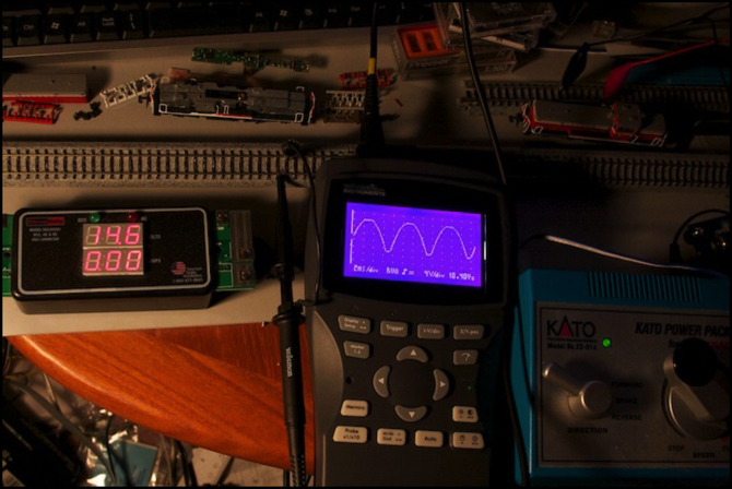
I’ll take the big one first: N-Scale trains use 12 volt power. Kato’s power pack is held up as an example of this, and sure enough it says “0-12V DC” right on the back. Stick a meter on one to confirm this, and you may get some odd readings however, as myth #2 is the Kato’s pack puts out pure DC. That’s something I’ve read on very many websites. Maybe it was true of earlier models. But I saw some odd behavior when I was trying to measure mine, and it got me suspicious enough to put an oscilloscope on the output (the coincidence that I’d just bought one and wanted play with it had nothing to do with that, of course). What I saw is shown in the photo above. With the output of the pack turned up to full, the track is receiving a rectified sine wave (the negative valleys are converted to positive peaks, so each peak shown is a half-wave 8 ms in duration). The scope shows the peak voltage as about 18 volts (I’m not yet convinced it’s all that accurate, but I don’t think it’s off by more than a couple of volts), and the RRampMeter is showing RMS voltage as 14.6 Volts. Neither of those is 12 volts.
It’s not too hard to produce smooth DC. I measured a cheap MRC HO power pack I have, and it was giving a straight DC output that was ruler flat on the scope. So this is almost certainly intentional; it’s essentially a form of “pulsed” power, and pulsed power makes DC motors work more smoothly at low speeds, particularly with dirty track. I’d guess they’re just using the unfiltered output of a rectifier driven by their 15 Volt AC wall-wart transformer. My meter says it puts out 16.5 V AC RMS, and that’s probably going to drop down in the electronics to something like the 14.6 volts RMS I observed on the track. The problem is that you’d normally want the option to turn the pulses off at higher voltages, and that’s not possible with this design, even if you had some way to know they were there.
Since Kato’s packs are made for Kato’s trains, presumably they’re well aware that the supply is 14.6 volts RMS (18 volts DC peak), rather than 12 volts DC, and thus their trains are safe to run on this voltage. I’ve heard that their trains will run fine on just 10 volts (and my experience agrees with this, as they run quite smoothly on around 1/4 throttle, and rather fast on even half-throttle). But what this tells me is that I don’t have to be too worried about my DCC voltage. In fact, I could set my system to “HO” (nominally 14 volts DCC RMS) without a care, if I ever decide I’m losing too much in the track when it’s set to “N” (12 volts DCC RMS).
Myth #3 is that when doing wiring, terminal strips are bad. Now part of that is that they’re subject to corrosion over time. I’m not convinced that’s a significant problem, as I had my HO layout wired that way for 15 years in a slightly damp basement (humidity was usually over 50%, until I finally installed a dehumidifier years later) with no trouble. I could see light corrosion on the exposed surfaces, but it didn’t affect the wires under the screws or the operation of my DCC sound-equipped HO trains, which presumably pulled quite a large amount of current (I could run two at a time on the Zephyr, and did, but never tried to run more, as it was a small switching layout without room for more).
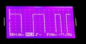
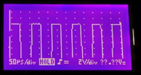
But terminal strips are also supposed to interfere with DCC by degrading the signal. I’d been pretty worried about that, and it’s the main reason I bought the oscilloscope. Below are two DCC signals, with the waveform magnified to only show the top half of the 24-volt signal. On the left is the output of my Zephyr, wired to a 2-foot length of test track, with no train. On the right is the output of my DCS100, as measured from the track under the Urban Station, about 20 feet as the bus wire runs, and around 10 sequential terminal strips and crimped spade connectors, away, and with a train running in the electrical section that the scope was connected to. Now there is a bit of distortion to the signal; the rise isn’t quite as fast (you can see a step partway up the edge of the wave), and the top as a bit more roughness in places (but it’s a fraction of a volt; it’s two volts between dots on the screen). But I’d have to call that pretty darn clean as square waves go.
Since I’d already decided to use terminal strips, it’s nice to know that they aren’t as bad as many think, but that’s not going to change anything I’m doing, since I’d already decided to take that gamble.
Myth #4 is that N-scale trains consume about 300 mA (0.3 A @ 12 V DC) of power. I’ve seen this one from numerous sources, and it was probably the right number twenty years ago. It’s not at all representative of a modern N-scale locomotive, or even a fairly long lighted passenger train.
I finished installing lighting kits in the first six cars of the E233 train I’d converted to DCC. This had an EM13 motor decoder in the motor car, FL12 light decoders in the two cab cars, and DC LED lighting kits (DCC compatible, but “always on”) in each of the passenger cars. The maximum power draw observed on my RRampMeter was 70 mA, and at most speeds it was 50 mA or less (just 10 mA at full throttle, where the motor is most efficient). Now stall current for this model is about 240 mA, and that’s probably drawn for very brief durations when accelerating from a stop. And trains with bulb lighting could potentially use over 300 mA. But most of my trains are LED-lit (or unlit), so my worst case even with 15-car trains is probably around 100 - 150 mA, not 300, since few of those will be accelerating simultaneously.
So my 2.5 Amp Zephyr could have driven about 16 or more trains, not the 8 I thought it was limited to (it’s actually limited to 10 by its software, so I was going to need the larger unit eventually anyway). I’m still glad I bought the DCS 100, but I could have waited a bit longer.
I’ll admit that some of this myth is my own fault. I’d seen a few comments online about 30 mA trains, but I’d dismissed them as none described actual measurements, and the majority of the comments had been about 300 mA loads. So I’ve been tossing the 300 mA figure around on these pages for a year.
That’s it for myths (so far, anyway).
In terms of the monthly status report, well there’s not much tangible to show for it. I have done quite a bit of electrical work, getting the wiring for the Rapid/Shinkansen line ready (still not done) and equipping my first train (but I need to do the four-car expansion set, not just the six-car base set I’ve done so far). In terms of scenery, I’ve nearly finished the “roof” over the subway on the Riverside Station scene, with just a bit of painting left to do, and a slight height mis-match to correct where it meets the unsceniced end section. I may actually get that finished this weekend. I also finally glued down the main part of the embankment on the River Crossing scene, that I’d held off gluing for a couple of months as I worked out scenery adjacent to it.
And the big success of the month was learning to make a mold and cast plaster for retaining walls. I now have the two “level” retaining walls of the Riverside Station, and will be able to use the same technique to make a bunch of walls with a 2% slope to match the descending line in the station. That’s real progress.
As an aside, if you’re at all interested in modern Japanese overnight “sleeper” trains, Kato’s just announced the December release of an update of the Cassiopeia train with an EF510-500 in the matching silver paint scheme. This train runs from Tōkyō’s Ueno Station to Hokkaido, and largely caters to the tourist trade (it’s describe on my Prototype Resort Trains page). If you want one (or all of the expansion sets), reserve it now, as this is a sure bet to sell out. I’d already reserved the Hokutosei (November release), but I’m still thinking I might go for this one also.
Other website changes:
- Updated the “Phase 2i” Construction page.
- Updated a number of pages in the Electrical section, and rearranged what was there some more. This included adding pages about DC Power Packs and DCC Decoders. I also updated some of the photos on my Kato Decoders page to provide larger images, and updated my DCC Power Systems page.
- I’ve added photos to both the Decoder and Electronics photo albums.
- I’ve updated text on my Roster, Commuter EMU, and Reservations pages to reflect my new Jōban line E231-0 (Kato 10-553, 5-car train) and Shōnan-Shinjuku E231-1000 (Kato 10-594/595/596, 10-car train) sets. No photos yet, as these just arrived.
== Comments copied from old system:
Monday, September 6, 2010 - 12:02 PM
Don
Good work with the o-scope (BTW, what model 'scope is that?). FWIW, my Tomix throttle puts out a solid 12V DC at full throttle, and is smooth as butter: Not a bit of pulse. Interestingly, it was designed for 100VAC input, and I'm feeding it about 110V—I wonder what it puts out on the home market?
I had never heard #3 before. Terminal blocks can only degrade signals if the connections were bad, but as you noticed yourself, the terminals are designed for solid connections—clamped down nice and tight, corrosion won't really affect connectivity, and if it did, it wouldn't introduce noise, only increase resistance (as contact area is lost). So claims that terminal blocks are bad sounds like bad advice handed down over the years as solid information—a syndrome model railroaders are particularly prone to. Which is why, by and large, I tend to look for my advice from roboticists.
(And while I don't think that #4 is really quite false—we've had this discussion already—I'm ready to concede that it is misleading, as in its usual form, it leaves off too much nuance—namely, that the 300mA figure is the stall current, and that not every loco is going to draw that much current at the same time except under freak circumstances.)
Monday, September 6, 2010 - 06:32 PM
KenS
Don,
The scope is a Velleman HPS10. A fairly simple scope, without the sophistication a serious hobbyist might need, but quite suited to my limited requirements.
If the Tomix pack puts out flat 12V on 110, then I'd expect they're doing some regulation, and it would also put out 12V on 100. As I'm sure you know, DC voltage regulators you can use with an AC-DC converter circuit (transformer plus rectifier) are pretty cheap and simple, and many wall-warts these days have them built-in. After all, commercial U.S. power wanders all over the place, from ~109 V AC to around 130 V AC, although it's usually in the 113-120 range (I have a volt meter on the computer rack next to my desk, and I've watched it do that for a couple of years now). The Japanese grid may be more stable, but there's no reason to assume it is. It's 117 right now, but a few days ago when everyone was running their air conditioners it was several volts lower.
Considering how the Japanese mix industrial and residential areas, their home power may be quite a bit dirtier than ours. It makes sense that if they want 12V power, they'd take some steps to ensure that's what they get. The Kato waveform has a slightly clipped look to the top of the peaks that makes me think they may be doing something to limit the peak voltage also.
I think the terminal block issue, which I've read in more than one place, probably derives from ones that get used on modular layouts, where connections may be made and unmade on a regular basis, and wire that's exposed to air one day may be the current-carrying portion on another (and screws may become worn and not make secure contact). Over time that wire and the blocks are likely to corrode, although I'm not sure it would be any worse than most of the connectors I've seen recommended for modular layouts.
I agree that a tightly screwed down block should be effectively gas-tight and not subject to corrosion of the surfaces that meet to conduct electricity.
Your point about loss is a good one though. I have seen voltage loss at higher current (see my earlier notes about testing with an auto tail light) that suggest there is a fair bit of resistance in the path, some of which comes from the terminal blocks.
Perhaps I was reading too much into the warnings I'd seen due to my networking experience. I'm used to poorly crimped connectors in the old thin-coax Ethernet causing impedance mismatches, which cause reflections in the transmitted waveform, which ultimately corrupts the signal. The low signaling rate of DCC may avoid or minimize that kind of problem.
