


Adding a DCC Meter, And Related Topics
Although I wrote about the power panel previously, there were a couple of things left undone. I was missing one of the ammeters for the lighting power (the store I get them from had run out), and I’d misplaced one of my LNRP LocoNet Repeater panels, so I’d substituted a UP5 panel I took off the old HO layout. Also, I’d realized that my portable RRampMeter DCC volt/amp meter was useful, but wiring it into the system when I wanted to check something was a real nuisance. Over the summer I bought or found the missing bits, and finally decided to order a new RRampMeter (the version without the nice case) to mount as a permanent part of the circuitry (I’m keeping my other meter--the one with the case--for workbench and other testing uses). So it’s a good time to summarize what the panel does, and talk about the new meter a bit.
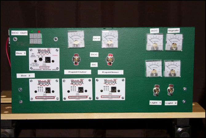
Looking at the photo above, the new RRampMeter is mounted top left, with just the red/green LEDs (“DCC present” and “AC Present”) and the Volt & Amp meters showing. Below it is the UR92 for wireless throttles, which also has its “track power” LED connected to Bus #1, so I can see if the main track power bus is live. On the bottom is a row of three LNRP panels. These subdivide the LocoNet into a signaling section (not yet used), a “switch” section (connected to DS64 stationary decoders that throw turnouts) and a throttle section (connected to the UR92, a UP5 panel on the back of the panel used to power throttles when the layout is shutdown, and a UP5 panel on the far side of the layout, for when wireless isn’t working and I need a walkaround throttle). That’s in addition to the “protected section” which contains the Command Station and the LNRPs, and will eventually contain the LocoNet-USB interface for the computer. These are also connected (L to R) to the second power bus (presently fed from bus #1, but for future booster expansion) and the two busses that feed the outer loop (#3 and #4).
The outer loop tracks are independently switchable between DC and DCC. Above the two rightmost LNRPs are the toggles for this. The LEDs on the LNRP will indicate if DCC (orange) or DC (red, green or dark) is selected for each.
Above the two toggles are the (unrelated) ammeters connected to the first two outputs of the PS2012 power supply. “DC2” isn’t wired to anything today; it’s just there for a future booster. The left ammeter (which should be labeled “DC1” but I forgot to add that label) shows total power draw by the DCC systems. DC1 essentially shows the same information as the RRampMeter, except that it’s wired before the command station, so it shows any additional power lost there. It exists to let me know if I’m approaching the 5 Amp limit of the PS2012 wiring harness (which has a circuit breaker built in).
Over on the far right, the two ammeters on the top (“ACC” and “Signals”) show the third and fourth outputs of the PS2012, the first of which powers the DS64s, and the second will eventually be dedicated to occupancy detectors and signaling systems.
Finally, on the lower right are two toggles with ammeters above them. These are for the two 1.5 Amp power supplies that will (eventually) feed LED lights in buildings, streetlights, and similar. The toggles allow lighting to be turned off for “daytime” and on for “nighttime”, and the Ammeters are so I’ll know if I’m getting close to the supply limits.
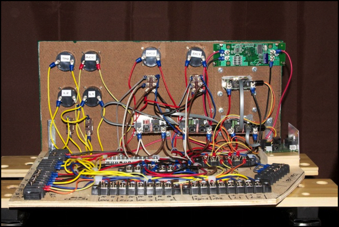
And that’s really all there is to it. The panel itself isn’t very complicated, although it does have a lot of wires:
Adding the RRampMeter was pretty straightforward. The only tricky part (aside from cutting a hole for it, which would have been much easier if done before all the other meters and wires were added) was that the RRampMeter “I” (the kind without a case) doesn’t include screw terminals that are pre-installed. Instead you get four that snap in to the circuit board, and should be soldered in place (although I think they’d likely work fine without that). I soldered them and then wired the panel between the input terminals from the command station and everything else connected to those terminals.
BTW, my RRampMeter says it’s a “2009 version”, which apparently improved accuracy at low amperages over the earlier models. I didn’t try a side-by-side comparison with the old one though, to see how much it had changed.
Some DCC power is used by the LNRP and UR92, even though they’re separately powered. With no train on the track, power consumption was 130 mA @ 11.9 Volts DCC (0.13 Amps on the meter).
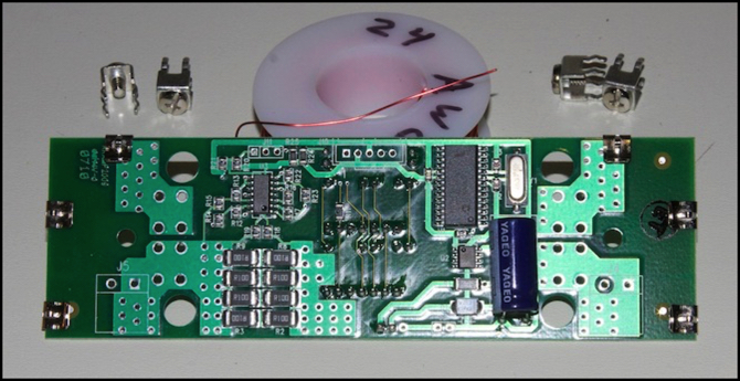
RRampMeter Back - before installing terminals
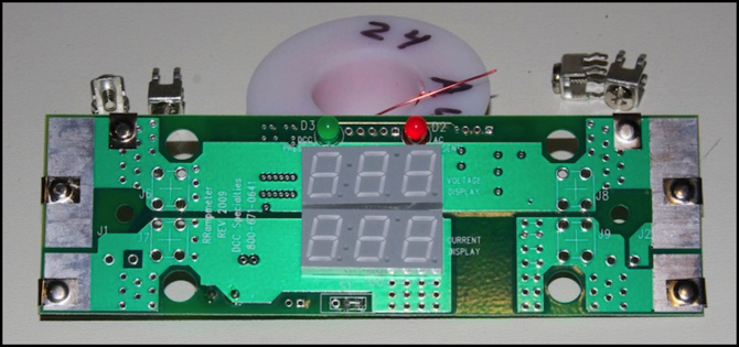
RRampMeter Front
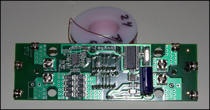
RRampMeter Back - with terminals
With the new panel all assembled and wired back into the layout, I ran a few trains to see how they worked. Voltage ranged from 11.7 (most of the time) to 11.9 (nothing active), and current from 0.13 Amps with no trains on the track, to 0.32A with my ten-car Joban E231 running at maximum throttle. Interestingly, I saw higher current at maximum throttle than at low-speed running (0.29A at low speed, and 0.31A at “prototypical maximum”, around 26 and 40 on the 0-99 Digitrax scale). That differs from what I’d seen in earlier testing, where low-speed had drawn more power. I need to do more tests, but that’s a project for another day.
But I can summarize that my ten-car train, with all cars lit and the head/tail lights on, draws 90 mA just sitting still, and peaks at about 190 mA at maximum throttle. I also saw this vary by about 10 mA when the train was climbing or descending a 2% grade, although I don’t think it ever got above 190 mA (0.32 on the meter). With that kind of power, my 5 Amp command station could run 26 trains (probably a bit less in reality), which is far more than I’ll ever have moving on the layout.
Other website changes:
- I added all of these photos to the Electronics photo album, so you can see larger copies if you like.
- I added a “Policy” page to the site (linked from the home page) to centralize all of my website policy info. This probably isn’t needed for a personal site, but I wanted someplace to put a notice that this was a personal site, not sponsored by anyone, and I had a few other things worth centralizing, so I made something more complete.
- More work has been done on the Electric Propulsion page, but it’s still a work in progress.
- I’ve updated the entry for the E217 on the JR East Suburban Trains page.
- I’ve updated the photos of the power panel on the Power Wiring Standards page, including a photo of the lit panel in use. That page is something of a catch-all, and I may rewrite that section eventually to make the info more sensibly arranged.
