


Building A DCC Booster
25 January 2011 01:45 Filed in: Electrical,DCC
Note: there seems to be a problem with iWeb’s comment feature, which is apparently a well-known problem that sporadically affects iWeb sites. Cause and fix are unknown at present. Sometimes it fixes itself, so you can try again later. Or, if you want to contact me, email to the address on the Who Am I page will work.
Followup: I reloaded the entire site (and didn’t that take some time) and it looks like it’s working now.
Or not, seems to have broken when I updated this page. Lovely.
-----
It’s been longer than usual between updates. That’s partly because other things kept me away from working on the layout or this website (the layout is still apart awaiting final assembly of the backdrops), but mostly it’s because I’ve been spending evenings the last couple of weeks building and testing a DCC booster kit. I didn’t actually need another booster, but Don offered me one and it seemed like a good way to gain some soldering experience (which it was, although I had a bit of a scare when it didn’t work).
For those not familiar with DCC, the booster is the part that merges the digital commands from a Command Station with a power supply to run trains. Typically the first booster is integrated with the Command Station, and you add more as you need more power, subdividing the layout into “power districts” each wired to one booster. You really only need a second booster if you have a very large layout. Well, if you were running HO trains with sound, you might need one for the third or fourth loco, but for us N-scalers without sound, we can probably run 15-20 trains off a small system like a Zephyr.
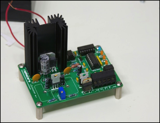
The booster is Don Goodman-Wilson’s LOLbooster, which is well documented on his site. You can buy a kit, or a board from him, or just follow the diagram and do it all yourself. I should note that I have no commercial interest in this kit, and this isn’t a formal review anyway, just a few notes on my experiences. I have a page with a more detailed description of the assembly and testing.
To my great surprise, the booster works and I’ve used it with my Zephyr as the Command Station to run a DCC-equipped DE10 back and forth on a length of test track. As I type this my booster just finished running for four hours powering a 2.5A load of lightbulbs (the booster is rated for 3 Amps max) and didn’t seem to be having any problems. The only reason I turned it off was so that I could go to bed. As described on the other page, the booster does presently have a problem detecting shorts at power-up, although my Zephyr seems to have experienced a similar problem. But it works and, not counting testing, it only took me about four hours to build (and I’m very slow).
Along the way I learned a few lessons, like: be really careful inserting IC chips in sockets not to bend a pin (I’ve installed dozens of socketed chips over the years, some much larger than these, but I got careless and bent a pin, and as a result the first time I powered it up, absolutely nothing happened, which was not fun to track down).
What really surprised me though was how easy it was, that one problem aside, to build a fairly complicated circuit, given a circuit board, a box of parts, and some fairly good instructions. This has me thinking of some other things I might do that had seemed too complicated before (more on that eventually, but probably not soon).
So, I built a booster. It works. I had fun and it was a nice change of pace for me. It’s always good to try something new from time to time, particularly when it works out. But now it’s time to get back to working on the layout itself.
As noted, backdrop construction came to a near halt. I did get the Urban Station backdrops assembled, but they await priming. And I still haven’t glued the photos to the Riverside Station backdrops, although they’ve been ready for two weeks now. I did, however, finish all the plastering, gluing and painting for the subroadbed (WS risers and plaster cloth) and roadbed (WS foam roadbed) through the Riverside Station. I’ll probably do some touch-up painting on those while I work on the backdrops, but I’m hoping I’ll have everything back together in the next two weeks and be running trains again, this time on all six tracks.
Other website updates:
- Lots of pictures of the booster on the Electronics photo album.
- A picture of my new Shiki 600 + Yo 8000 Schnabel car set (Micro Ace A8570, already sold out) on the Train photo album. This was a preorder due in February, which turned up a month early.
- Construction update on the Phase 2j page and photos on the Construction photo album.
- I’ve added an “under construction” page describing the technical details of the E231. It’s a long way from complete, and mostly replicates what you’d find on the wikipedia page at this point, although that will eventually change.
- I’ve also added another technical page, also “under construction”, where I’m going to describe some of the other technical elements related to car/train design. For now it has an abbreviated description of some of the different couplers used on Japanese trains.
