


February 2011 Status - Occupancy Detection Revisited
Work has progressed slowly this month, partly from distractions, and partly because I’ve been reluctant to finish up the block occupancy detector wiring. I finally realized that the reason for this was that I wasn’t happy with my hybrid approach to occupancy detection and transponding.
To recap, my Subway and Commuter loop tracks were to be divided into blocks, with Digitrax BDL168 occupancy detectors and PM42 circuit breakers (circuit breakers are typically one per track per table, whereas there may be two, three or even four detectable track sections on a single track on one table, and more in a couple of cases). The PM42 provides for four circuit breakers, which is a nice fit for the four tracks, and the BDL168 is divided into four independent quadrants (so each can be wired to a separate circuit breaker), each with four block detectors. I’d originally planned one PM42/BDL168 per scene, meaning that wires would have to cross a table boundary in the Urban and Riverside Station scenes.
And that was a problem, for several reasons. First, running wires between tables violates my “keep all wires except bus wires local” design goal (it makes the layout harder to disassemble), second while the BDL168 can support 16 occupancy detectors, in some places I needed more than four on one track, which broke the association of the PM42 circuit breaker element to a single track, meaning a short would shut down a second line. And finally, I wanted to do Transponding, and the BDL168 only supports 8 transponding sensors (using a pair of RX4 sets), meaning some blocks would be able to report which train was in them, and some would only be able to report that some train was present, but not which. None of these were fatal flaws, but they were eating at me. And I finally realized that I only needed two more sets (seven instead of five) to fix these problems.
So, after a bit of dithering, I resolved to have one PM42/BDL168 on each half of the two long scenes, one on the River Crossing scene, and two more on the unsceniced loop (it has a lot of track, including some of the linking tracks between the Commuter Line, Subway Line and future helix to staging). With this (see the list of track sections and their assignments to circuit breakers and detectors on the Power Wiring Standards page) I was able to limit myself to eight detectors per BDL168, all with Transponding, and keep the PM42-to-track association clean. I also got rid of almost all table-crossing wiring (maybe all, but there’s a couple I haven’t exactly decided where to place the feeders for yet).
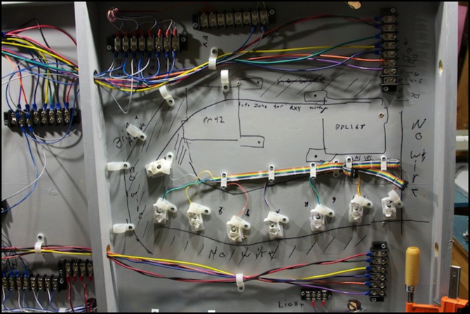
In the photo above, you can see the left half of the Riverside Station scene, with the eight RX1 transponding sensors (the white blocks on ribbon cable) and the outlines of where the PM42 (left) and the BDL168 (right) will go once I wire those up. Placement of the RX1 is a bit tricky, as they’re inductive coils (essentially radio receivers sensing alternating current in a nearby wire), and can’t be near other wires that might interfere with the signal they’re trying to pick up. I’d planned my track on the front and rear edges of the tables to leave room in the middle for the sensors to be mounted to the underside of the table (track above them within 2” would be a problem), but with all the wires to and from them, it’s going to be pretty crowded around them.
So, now it’s finally time to solder all the wires to the card-edge connectors. Why, oh, why does Digitrax use card-edge connectors instead of screw terminals? It’s not like soldering to a friction-fit connector is going to be any more reliable than a firmly tightened screw terminal. And you have to solder each wire to two pins if it’s carrying more than 3 Amps. Not to mention having outboard inductor loops that take up huge amounts of real estate. You could do that onboard with a good DSP chip, and DSP chips aren’t horribly expensive these days.
I’m really coming to hate the PM42 and BDL168; they’re just not up to Digitrax’s usual standard of good design. I have no doubt they’ll work well, as they’re both long-proven designs, but they just feel like a hack compared to something as polished as a DS64. Anyway, annoying or no, I already own a bunch so I’m going ahead with them (and I pretty much have to, if I want to use transponding, and with Kato using Digitrax in their EMU DCC decoders, that’s pretty much a given).
And then maybe I can finally install the backdrops I made last month and reassemble the two Riverside Station tables. It’s about time.
Other website changes:
- I updated the “Phase 2k” Construction page, although not with a whole lot given my inactivity.
- Added new Reservations to my list, and moved a few things to the Recent Arrivals page.
- Added a picture of the square-end element for the new (tiled floor) island platforms to the Overhead Transit Station page. I’m going to be using these on the Express line of my overhead station, when I finish up that track’s wiring (shortly following the reassembly of the tables).
- I updated my Roster and Limited EMU pages to note the arrival of my second new Narita Express 6-car train (now I can make a full 6+6 set).
- As noted above, I updated the Power Wiring Standards page, and also the DCC Wiring page (to reflect the changed number of circuit breaker/detector sets, and clean up some older text).
- I’ve added a new page describing LED Strip Lights, which I’ll be using for building lighting. This page is still very much a work in progress, but I’m planning to light the Riverside Crossing’s Subway Station soon, and that should give me some material for it.
== Comments copied from old system:
Friday, March 4, 2011 - 10:33 AM
Don
By "outboard inductor loops", do you mean the RX4 elements? Those are current-sense inductors, which cannot be simulated by a DSP chip. They work a lot like the inductor pickups on an electric guitar, except they detect a moving electric field, rather than a moving magnetic field. The idea is that they detect a signal being transmitted by the transponder, something like that.
Anyway, the edge connector is supposed to plug into a blue plastic thing that looks easier to solder to, on this page: http://digitrax.com/prd_statdec_bdl168.php Did you not get one of those?
All that said, the design of the BDL168 has long boggled me too, and was one of the primary reasons I never ended up buying into the Digitrax system. It just looks unnecessarily complicated! So many wires to keep track of, so many to solder.
Friday, March 4, 2011 - 07:11 PM
KenS
Don, yes I meant the RX1 loops (each RX4 is four RX1 on a multi-wire ribbon cable). And you'd still need inductors with a DSP. But the reason you need 2" separation is noise floor. And DSPs excel at pulling signals that are slightly stronger out of a background of similar noise (which is essentially what they do in DSL implementations).
I'm not an electrical engineer, so it may be more complicated than I think. But I think with a DSP, you could either put the inductors on the board or make them smaller and with much less separation required, and still separate the signal you want (the mildly stronger one) from those of nearby wires.
I do have the blue edge connector, and it probably will be solderable (although getting 5-Amp wire to make a good pair of solder joints with it per Digitrax's requirements will be a bit tricky). But it's soldering to it and then snapping the board into it that I object to. It's much harder to mount than the board alone would be, and very easy to damage in the process or when adding/removing the board. And for all that, I get a friction-fit connection to the board, rather than something I can screw down tight.
Even with all those wires (nearly 40 on the BDL if fully populated), I'd rather unscrew them each time. It's not like removing the boards would be commonplace.
Tuesday, March 8, 2011 - 02:37 AM
Don
Ah, I see what you are talking about. Yes, a DSP might make some sense then.
I still generally agree that the whole thing is a bit of a mess, esp the edge connectors :( Now to read your latest post…
