


DCC Power I
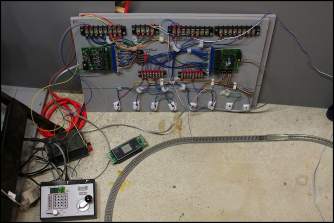
After assembling the first of my DCC protection and Occupancy Detection boards, I decided I wanted to test it and get some experience with using it. So I set up my loop of test track with insulated rail joiners separating it into two halves, and connected the feeder to outputs 1 and 2 of the BDL168, which correspond to RX4 A, detectors A & B. All of these are powered by PM42 section 1. For DCC, I used my Zephyr, and for the DC supply I used the 2 Amp, 12 Volt supply I plan to use for these systems (it’s the black box just above the Zephyr in the photo above). Powering it up, nothing went “Zap!”, which I count as a success.
I then hooked up the computer I’m using with the layout (it’s also the one I’m using for programming decoders), an ancient iMac (c. 2001) running JMRI, with a RR-CirKits LocoBuffer USB (the beige box left of the Zephyr).
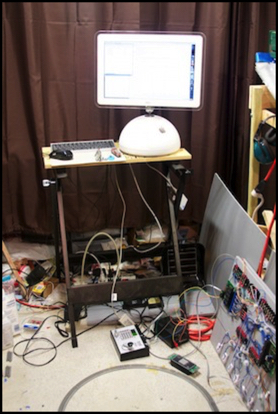
Computer with DCC test systems
As a sacrificial lamb, I mean test unit, I used the first DE10 I’d installed a decoder in, as I didn’t have any throw-away locos with DCC, and I didn’t want to risk one of my commuter units. I’d hate to fry the DE10, but at $74 (plus shipping) it wouldn’t be a disaster if I did. Fortunately nothing fried (I did check the track voltage using my RRampMeter before I put the DE10 on the track).
One of the nice things about JMRI is that it will log messages on the LocoNet, so I was able to record the testing. Here’s the first loop of the DE10 (note that the “start loco” and “stop loco” are notes I added to the log so I’d know what I had done; on this log, I forgot to turn on timestamps).
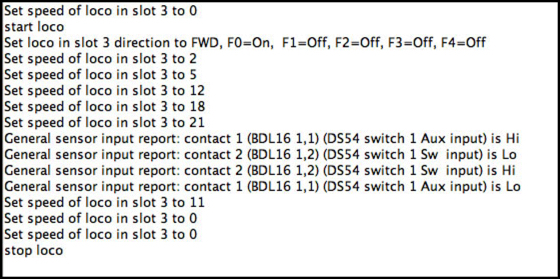
You can see in this the DE10 (address 3) set to speed 21, the first two sensor input messages are when it moved from block 2 to block 1 (sensor 1,1 going “Hi” is it entering block 1; the BDL reports occupancy as four groups of four outputs, so block #5 would be 2,1).
That’s pretty cool, but there’s no transponding. Oh, I forgot to turn it on in the decoder, oops. I quickly fired up the programmer within JMRI, and set that on (programming on the main; it took less than a minute). Then I ran the train around a couple of times, but this time I remembered to turn on timestamps, so it’s easier to see the transitions:
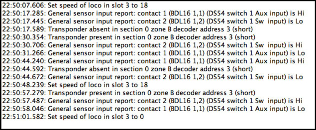
You’ll note a problem here: for some reason, Transponder zone A isn’t reporting. I’m not sure if that means I’ve got a busted RX1 sensor, or if there’s some other problem. Diagnosis will need to wait for another night. But you can see Zone “B” show “present” when detector #2 (1,2) shows “Hi”, which is what should happen there.
Not shown here, I also played with the PM42, shorting blocks with a wrench and watching it trip the protection on the PM42. It looked like the Zephyr also tripped momentarily, but I haven’t yet set the PM42 up, so it’s defaulting to normal trip speed and a 3 Amp trip current, which is probably a higher trip current than the Zephyr. I’m going to set it to 1.5 Amps trip (the lowest setting) and either “Faster” or “Fastest” trip speed, to minimize risk/damage to my model trains. A trip current of 1.5 Amps is far above what any set of four blocks will ever draw (at least double, and probably more, what four trains without sound would use) and I have at most one quadrant of a single BDL connected to one quadrant of a PM42, so that’s my worst case.
So what I have here is the system essentially working as designed (except for the RX1 issue). Which isn’t really a surprise, but it’s nice to see. Now I need to set the two devices up properly (giving them unique addresses for the layout LocoNet and setting option switches to control various features). I’ll have another post on that once I get to it, hopefully soon. And I need to test the remaining outputs of the BDL and see if there are any issues with the others (and figure out what’s wrong with Zone A, although I have a couple of unused zones I can switch to if necessary).
Administrivia
I think I’ve figured out my export problem with RapidWeaver. Basically it’s not a RapidWeaver problem, as much as it is a Stacks problem. Stacks is the page type that’s provided by a third-party plug-in which enables somewhat structured page layout. I’m mainly using it for clean two-column and three-column image layouts.
The problem is that both RW and Stacks store images as encoded data in an XML file in the master database. This is likely to enable images to be manipulated. However, RW does this more efficiently and allows images to be compacted to the size needed, while Stacks does not. I tried a test with a page with 14 images and some text. Using stacks it took up 14.3 MB in the master copy, even though the exported page with separate images added up to just 487 KB. The standard RW Styled Text page type stored the same page in 4.8 MB by default, but using Normalize Images after I’d resized the images to the size I used (many just 30% of the original size) this compressed to 651K in the master).
Further, on export Stacks has some kind of memory leak, so memory is consumed by each exported page and never recovered, until the application hits the limit provided by 32-bit addresses (RW is a 32-bit application), and then everything fails.
So, my plan now is to revert to not using Stacks except where I really need multi-column. Many of my pages don’t, as I can put two smaller images side by side in Styled Text, I just can’t put separate captions under each; that’s a restriction I can live with. It’s going to be a lot of work to convert all those pages, but I should get back to being able to cleanly export the site once I do.
