


Electrical Substation
It might seem like stating the obvious, but an electric railways needs a supply of electricity for the trains to run. I’m not talking about the model trains, but the prototype. A typical commuter train can use up to 1.5 MW (megawatts) when accelerating. A Shinkansen can use 10 MW. At any given moment hundreds of trains are operating in the Tōkyō area, with power demands larger than a small city.
Where does that power come from? JR East buys some of it from the local utility (Tōkyō Electric Power Company, or TEPCO). TEPCO operates fossil, nuclear and hydroelectric power plants, transmitting power along transmission lines at up to 500,000 volts (500 kV). At substations this is reduced to much lower voltages (6,000 volts or less, according to wikipedia, although distribution lines can be higher-voltage) and sent along street utility poles to local pole-mounted transformers that step it down to 100 or 200 volts for residential use. Industries typically take the distribution voltage and have their own transformers as needed. Both Transmission and Distribution lines are typically three-phase AC power, with three wires (plus a ground, which is often not present on towers). AC is used because transformers only operate on AC, and higher voltages can be sent longer distances.
JR East also operates their own power plants and transmission lines (and presumably substations, although I haven’t found photos of any of those).
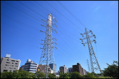
Shin-Yokohama Transmission Lines: The right-hand line is apparently owned by JR East
Photographer: ykanazawa1999
You can see these and some other some reference photos on my Electrical Images page.
The Prototype
The railways take power and transmit it along the line. In the photo below, the three wires on the arch above the middle of the train are likely a high-voltage AC distribution line (the higher location and larger insulators are suggestive). The two wires on the T-shaped structure may be a separate lower-voltage line, or they may carry the 1,500 Volts DC fed to the train (the catenary below the metal supports that the train gets power from isn’t very good for transmitting power, and had to be fed fairly often from a supply line).
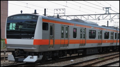
Photographer: ykanazawa1999
To get the power to a form the train can use, it must be stepped down to 1,500 V DC (for most non-Shinkansen) and converted (rectified) to DC. Once in DC, it has a limited ability to be transmitted, so the transformers and rectifiers used for this purpose are located about every 2 km along most lines (they’re pretty easy to spot with Google Earth, look for rectangular buildings with structures crossing the tracks to carry the wires). These are typically small, two story buildings immediately next to the lines and connected to them with more elaborate superstructures than the usual catenary arches.
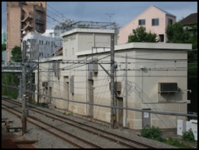
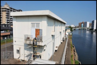
Lineside Transformer Buildings: L: Tokyu-Toyoko Line, R: JR East Keiyo Line
Photographers: Grant “gmat” Matsuoka, ykanazawa1999
Grant’s photo copyright, used by permission. (originally posted to this thread on JNS Forum)
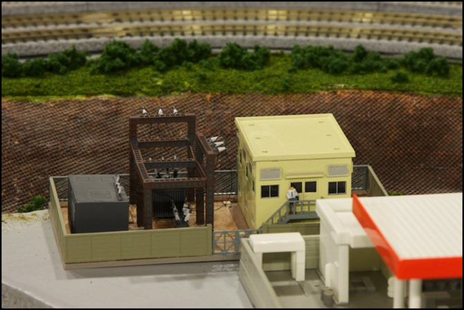
The Model
With that background, I wanted to include something similar along my model railroad. Unfortunately I hadn’t really allocated space for a transformer building next to the tracks anywhere, so instead I decided to build a small electrical substation serving the Village area that included the transformer facility. This was facilitated by Tomix making a kit of a small substation (Tomix 4023, Substation (sectional)). This was of an older facility, but had the basic elements of a substation: fenced gravel yard, metal girders with porcelain insulators, transformers, as well as a small two-story building with windows on the upper floor only. With a bit of tweaking, this would work. The metal girders were actually several interlocking parts that could be arranged in more than one way, although the manual (in Japanese, of course) showed one way to assemble them.
When placing a structure on the layout, I want to have a story for it, if only in my head. This one’s was that the village’s isolated location with hills carrying a transmission line (I’ll get to that) between it and the rest of the city on one side, and the river on the other, made it useful to locate a small substation there to feed both the village distribution network and the railway. This gave me an excuse to merge the two facilities in a way that probably isn’t strictly prototypical, and to locate it in the village rather than up on the embankment with the tracks.
The substation comes with one transformer and parts to make several circuit breakers, but to fit the story, I needed a second transformer (one for the village, one for the railway) and found a small resin casting in a local hobby store (basically a rectangular block with a couple of light-relief maintenance hatches and ventilation grilles). I arranged the metai structure to make space for the second transformer, and applied some insulators in appropriate locations.
Then, because I didn’t like the colors it was cast in, I started masking and spray painting things in different colors, and after that I brush-painted several more (including painting rust over the steel girders I’d spray-painted gray, then wiping most of it off with a paper towel to leave a rusty-looking girder with steel showing through).
I also painted the building, first painting the interior walls with two coats of black followed by a coat of white, to make the walls opaque to light, as I plan to install a LED to light up the control room. I also modified the roof with an interior sheet of styrene (also painted) to block six ventilator mounting holes (the ventilators were huge and seemed unnecessary given the exterior louvers all over the walls). Then I sprayed the outside in a light yellow color. Finally, I built a free-standing false-floor at the second floor level with a control panel and a semi-roof. The LEDs will mount above the semi-roof, with light shining down on the front and rear near the windows, to illuminate a control panel and any figures I put inside.
The control panel is a set of photos of various control panels I found online (including one for the fuel pumps on a 747!), printed out using my sign-making technique, and glued to a strip of styrene. With interior lighting I think it may be visible through one set of windows. I also posed on figure on the outside stairway, and will likely put a second at one of the control panels, just to make the place look busy and give me an excuse for having the place lit up.
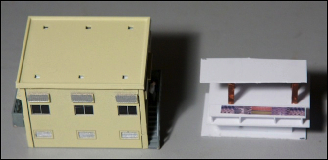
Substation Building (before roofing installed) and false-floor wit control panel
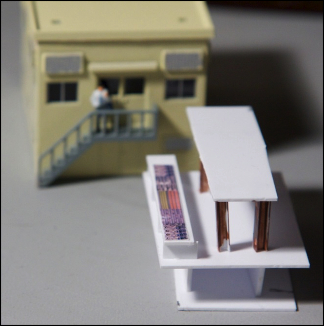
The false-floor assembly (before LED installation)
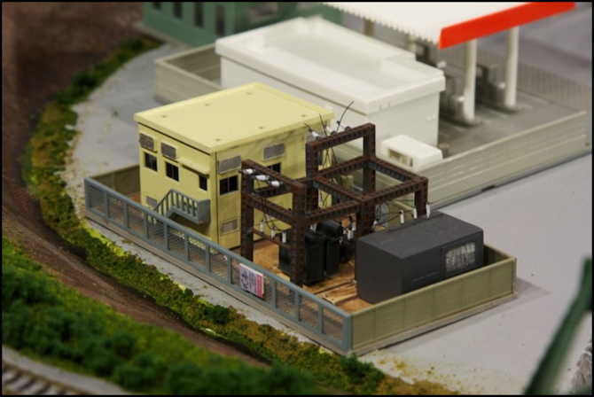
I also brush-painted various ventilation grilles in a silver color, as well as using the paint-then-wipe technique to add brown “dirt” to the white gravel of the base (it had started out gray).
The electrical wires are EZ-Line, an elastic cord that makes good-looking wiring and stretches so accidental touches won’t break it. I used a drop of quick-set superglue on each insulator to attach the lines (attaches in 5-15 seconds, and sets up in two hours). This represents one set of wires from the big transformer (the gray box with the silver grille above), through a ground-mounted circuit-breaker and up to the right-hand insulators in the photo above, which will eventually wire to the local street utility poles. And a second set from the smaller transformer to the insulators on the left, which will be wired to the track, or perhaps I’ll turn the building around and wire them the other way; I think I’d rather see the entrance from this side.
There will eventually be a set of transmission line towers across the back of this scene, built using the Kato/Heljan kits, but those are going to be a real pain to assemble (I’ve started, but it’s not going quickly). I’ll probably assume power gets from them to the substation underground (not unheard-of in a city, but not common; I just don’t have an easy way to get wires to the substation from them).
Finally, while I was making the control panel for the interior, I also made one sign of a bird pointing upwards, which I’ve seen used on a number of high-voltage towers as a warning sign, which you can see on the fence in the photo above (this one was taken from another of Grant’s photos, and made into a sign in my usual manner).
As an aside: assembly used five different kinds of glue. Styrene cement was used for most of the kit. Liquid Nails was used to attach the resin-block transformer. My usual sign-making glue (3M Scotch Quick-Dry Tacky Adhesive) was used for the sign and control panel. Super-glue was used for the sign mount and the wiring. And Woodland Scenics Scenic Accents Glue was used to attach the figure to the stairs, and will be used for some scenic materials as well.
There’s still work to be done. The interior lighting needs to be wired up, and tested. I’m planning to use yellow LEDs for an “incandescent” look, but they’re not very bright so I might change to white if that doesn’t end up looking good. I also want to add some grass and shrubs inside the fence (it’s typical of substation areas that don’t contain electrical systems) and I may add some more signs. Plus the building needs a “tarpaper” roof to hide the mounting holes for the ventilators. Finally, the loose ends of the “wires” need to be trimmed, but the glue on those was still setting when I took these photos so I have to wait a bit first.