


Wired Decoders II
Although the rest of my decoder order still hadn’t arrived, I decided to start work on my first wire-in motor decoder, to let me get some experience with the installation process, and to do some more experimentation. I used the Micro Ace Sobu E231 as previously planned, and to start with, a DZ125 decoder from Digitrax.
Now my original plan had been to wire-in a NEM651 six-pin socket into the car, and use the DZ125IN version of the decoder. The idea was that I could later swap the decoder for another model (like a Lenz Silver Mini Plus, or a TCS M1). The first problem I ran into was that NEM sockets are hard to come by. ESU makes one (part 51951), and I ordered a couple, but that was one of the things backordered. The second was that the M1 doesn’t come in an NEM651 version, and apparently nobody makes a wire harness that ends in a NEM651 plug.
But, I had a set of Miniatronics four-wire connectors (part 50-004-01) on my workbench, so I used those instead. I only need four wires for a motor decoder anyway, and this way I can get both parts: a socket for the train, and a plug with pins with a wiring harness for the decoder. It’s not as elegant as a decoder and NEM socket, but it will do the job. As it happened, I only had one package, and one plug and socket, so until I can order more, I’m only going to be testing the DZ125 I did first, but it’s a start.
The MA E231 is equipped with a skew-wound three-pole motor with dual flywheels. Pickups on each truck pass power to two brass rails on the underside of the floor, and contacts on the motor poke up through a bit of transparent insulating plastic (barely visible in the first photo below) to touch the rails. There are also two small holes in the floor, so a lighting unit can touch the rails from above. I’ll eventually install the interior lighting, so I need to keep those clear, but that’s not part of the current work.
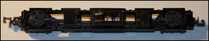
Micro Ace E231 Motor unit with floor removed
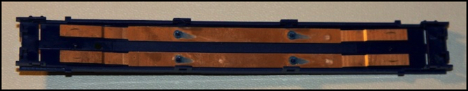
MA E231 Floor Underside (note abraded areas on the ends of the brass where the wheel contacts touch)
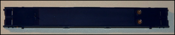
MA E231 Floor from Above
Wiring the socket was straightforward. Acting on a suggestion of Don’s, I notched the sides of the blue plastic “floor” unit so the wires to the motor could feed down under it and connect to the tabs on the motor from the sides. Kapton tape was applied to the brass rails above the motor, to insulate the track power from it. Below the motor tabs the original plastic insulator was retained, with some additional Kapton tape where I wanted to be safe. Separately I ran the other two wires from the socket to existing slots at the end of the floor, fed the wires down through those (I had to widen the slots slightly) and soldered to the end of the brass strips beyond where they contact the wheel pickups (you can tell where that is, as the brass is shiny there).
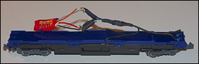
Before soldering, I cleaned the metal with a cotton swab soaked in isopropyl alcohol and let it dry, then I clamped the wires in place with some soldering heat-sinks and applied a bit of flux to the brass using a flux pen to ensure good contact for the solder (I used a flux that doesn’t need to be washed off). Then, very carefully, I soldered the wires in place. Except for one point where a heat sink touched the plastic and stayed there too long, no damage was done to the model (and the minor deformation there didn’t affect assembly and will be hidden by the body shell). After that had all cooled, I snapped the floor onto the motor assembly. It buckled up a bit in the center, but after some work to flatten the motor pins, it all went down nearly as good as new, as seen in the photo at the top of the page.
Soldering the harness to the decoder didn’t go as smoothly, and I’ll probably discard this one (or keep it for testing use) and do it again better. I cut the leads too short, did a poor job of stripping, and soldered in too much of a hurry. That all said, it worked the second time I assembled it.
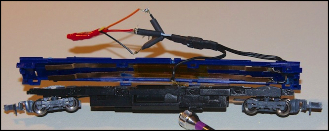
MA E231 with decoder socket wired in place (and decoder connected)
The first time it didn’t work at all, and I was baffled as continuity checks had shown I had good conductivity through the solder joints, with resistance of a fraction of an ohm. Eventually I realized that I had soldered the motor wires to the two left pins of the socket, and to the two left pins of the decoder plug, and of course left mates to right when you plug them together. I can never solve those topology puzzles involving interlinked steel rings either...
Fortunately the plug is symmetric, and flipping the decoder over reversed the wires to the correct position. After that, it started working.
Now it’s not elegant, but part of that is by design. Although I put lengths of heat-shrink tubing over the wires, I haven’t yet put them over the joints and shrunk them, and I’ve got the wires splayed apart so they don’t touch. This gives me a neat place to wire up my oscilloscope for monitoring the decoder’s motor output (I need to put the car on the Bachrus speedometer cradle to do that, but it’s more stable than the DE10 was; it only fell off twice).
I also did some checking of the default decoder settings, finding them identical to those of the EM13 I’d checked last week. In fact, the decoder version number (51) was the same too, suggesting that it refers to a specific edition of the FX3 feature set, rather than to a version of the hardware.
Before hooking up the scope, I ran the train around the test track, to prove it worked reliably (it did). I tried different settings of CV57 (the BEMF intensity CV).
I found that a setting of 15 (maximum) produced lurching speed changes at points on the test track where the pickup was poor, as the decoder over-compensated for the speed drop, and settled on 10 as a good value. I also tried it with 0 (off) which I hadn’t thought to do on my other trains. The behavior without BEMF was significantly worse where the track pickup was poor, suggesting BEMF has value on temporary sectional track where there will be occasional bad spots due to misaligned track joints.
I also checked the speed by timing the train around the test track. This produced a top speed of 322 scale kph with BEMF disabled, while top speed with BEMF set to 10 was 291 scale kph. So I’m losing some torque to BEMF. The difference would no doubt be larger with a ten-car train, but for a commuter EMU with a top speed of 120 kph or so, it’s not likely to be an issue.
Turning BEMF off when on the testing cradle actually caused the train to stop at a low throttle setting of 13. I had to turn it up to 40 (out of 255) to get reliable running. Comparing the oscilloscope traces of the motor control wires with CV57 set to 0 (off) and 6 (normal “on” level) show significantly longer pulses with BEMF enabled, so it’s clearly pushing more voltage (which is obvious from the speed also, although as usual the speedometer wasn’t reliable, so I couldn’t compare the two that way). This all suggests that the train will run much better at low speeds with BEMF enabled, and that matches my (so far) limited observations.
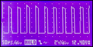

BEMF Off (left) and On (right), both with throttle set to “40” - note longer length of pulses in “on” setting
Something else interesting is that a couple of times I caught the scope flatlining when BEMF was enabled. Once it showed pulses on either side of the flat section, other times the length of the flatline was longer than the 0.6 millisecond width of the scope. This is probably the “turn it off and measure speed” behavior Don noted in an earlier comment.
I’m going to try some additional experiments, but this scope isn’t great at investigating longer waveforms. I really need to get a computer-controlled scope with better data-capture capabilities, but there aren’t many available for Macs, and the good ones are expensive. One of these days...
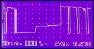
BEMF on as above, but with 300 microsecond pause in PWM
Digitrax really doesn’t provide a whole lot else to tweak. There’s a “turbo boost” feature that apparently compensates for supersonic PWM torque loss (probably some kind of extra kick at low rpm’s) but that’s on by default. There’s also a “kick start” which is a one-time boost to get a stopped train moving, but the default of “2” was enough to get the train moving at a throttle setting of “2” (the lowest my Zephyr will send other than 0), so it doesn’t appear to need changing either. Note that a throttle setting of 2 likely equates to a voltage level of 8/255=3.1% (if the default is the same as the speed table default) so it doesn’t take much to get the motor to turn.
My real problem was that once moving at throttle 2, the train tended to stall. That suggests that I need to use the speed table and set a throttle of “2” to some value of power higher than its default. There really isn’t anything else to adjust here, so having decided I want to keep BEMF enabled, all I really need to do for the DZ125 is pick a set of speed table settings as discussed last time.
But I’ve got my test train wired up, and once I get some more Miniatronics plugs I can see how the M1 works (and if my Silver Mini ever arrives, I can test that too). I also have another decoder I eventually plan to test with this rig, but more on that another day.